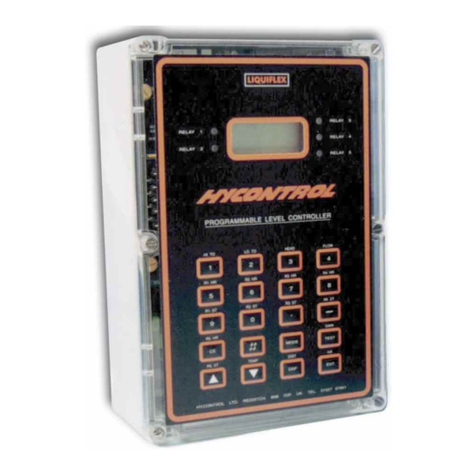
Hycontrol MINIFLEX LR User manual

Rev 0
MINIFLEX LR PROGRAMMABLE LEVEL CONTROLLER
INSTALLATION AND OPERATION MANUAL
Hycontrol Limited, Larchwood House, Orchard Street,
Redditch, Worcestershire, B98 7DP, UK.
Tel: +00 44 (0)1527 406800 Fax: +00 44 (0)1527 406810
Email: [email protected] Web: www.hycontrol.com

MINIFLEX LR USER MANUAL - INDEX
Page Drawings
Introduction 1
SECTION 1 Installation
Transceiver Mounting 2 Fig. 1
Transceiver Wiring 3 - 4 Fig. 2 & 3
Transducer Mounting 5 Fig. 4
Transducer Alternative Mounting 6 Fig. 5
Transducer Mounting Faults 7 Fig. 6
Transducer Stand Pipe 7
Transducer Cable Extensions 8 Fig. 7 & 8
Temperature Sensor 9 Fig. 9
SECTION 2 Easy start for Miniflex LR
Quick Start Guide 10
Principle of Programming 10
Keypad Definitions 10 - 11
To Enter Programme 11
To Enter the Password 11
To Change an Option 12
To Reset 13
Simulation Mode 13
SECTION 3 Programming the instrument
Parameter List 14 - 34
SECTION 4 Miniflex LR Default programs
1. Distance Measurement Mode 35
2. Level Measurement Mode 36
3. Contents, Volume Conversion 37
4. Pump Control 38
5. Open Channel Flow 39 - 40
6. Differential 41 - 42
SECTION 5 Commissioning fault finding 43 - 47
APPENDIX 1 LINEARISATION OF SPECIAL 48 - 52
VESSELS OR FLUMES
APPENDIX 2 SPECIFICATION 53
APPENDIX 3 INSTALLATION INSTRUCTIONS 54 - 55
FOR ATEX TRANSDUCER IN
HAZARDOUS AREA
APPENDIX 4 PARAMETER SETTINGS 56 - 62
APPENDIX 5 PARSHALL FLUMES 63
APPENDIX 6 WIRING DIAGRAM FOR 64
SYNCHRONISATION OF
INSTRUMENTS
APPENDIX 7 MINIFLEX LR PROGRAMMING 65 - 74
CHARTS

SECTION 1
MINIFLEX LR PROGRAMMABLE LEVEL CONTROLLER
USER MANUAL
INTRODUCTION
Miniflex LR is a programmable multi-purpose level measurement and flow control
instrument. It consists of two elements, a wall mounted transceiver, which has a display and
an integral keypad for programming, and a transducer, which must be mounted directly above
the surface to be monitored.
Ultrasonic pulses are transmitted by the transducer to the surface of the material to be
monitored and are reflected back to the transducer. The time period between transmission and
reception of the sound pulses is directly proportional to the distance between the transducer
and the material.
Since speed of sound through air is affected by changes in temperature, a separate or
integrated temperature sensor may be fitted to improve accuracy.
Miniflex LR is capable of the following functions:-
a) Distance Measurement (distance from a datum)
b) Level Measurement (height above datum)
c) Volume Measurement
d) Pump Control
e) Open Channel Flow Measurement (O.C.M.)
f) Differential Level Measurement
WARNING
DO NOT OPEN THE TRANSCEIVER
TERMINAL COVER WHEN THE POWER IS ON TO
THE SUPPLY OR RELAY TERMINALS.
IMPORTANT INSTALLATION REQUIREMENTS
1: A SWITCH OR CIRCUIT BREAKER SHALL BE INCLUDED IN
THE INSTALLATION
2: IT SHALL BE IN CLOSE PROXIMITY TO THE EQUIPMENT AND
WITHIN EASY REACH OF THE OPERATOR
3: IT SHALL BE MARKED AS THE DISCONNECTING DEVICE FOR
THE EQUIPMENT
Ref: MINIFLEX LR MANUAL Rev. 0 1

SECTION 1
INSTALLATION
Transceiver For ATEX hazardous areas refer to Appendix 3.
Enclosure mounting
Secure one of the three fixing screws provided with the instrument 30mm below the centre of
where the top of the instrument is to be located. This fixing screw will need to be left 4mm
proud of the surface allowing the instrument to be hung from this point. The instrument is
then secured in place by 2 more screws using the two mounting slots exposed when the
terminal cover is removed. DO NOT use excessive force when tightening the fixings and
avoid any distortion of the enclosure.
Ensure that the mounting surface is not subject to vibration and is not in close proximity to
high voltage cables, contactors or drive controls. The unit should not be mounted in a
confined space where temperatures may exceed the normal working temperature. If the unit
is mounted outside, it must be protected from direct sunlight or severe weather conditions.
Select appropriate knockouts in the base of the enclosure and fit appropriate cable glands to
maintain the IP65 rating.
(MODIFY)
BACK
INCREASE
DIGIT
OPTION
/ DIGIT
RELAY 1
RELAY 3
ECHO
LEVEL CONTROLLER
M
MINIFLEX LR
ENT
HYCONTROL LTD, ENGLAND
TEL:+44(0)1527 406800 Website: www.hycontrol.com
213.0
106.5
185.0
∅
5.4
10
198.0
31.00
MOUNTING POINT 1
FOUND ON REAR
137.0
MOUNTING POINT 2 & 3
(REMOVE TERMINAL COVER)
KNOCKOUTS FOR 1 HOLE 16mm AND 5 HOLES 20mm
∅∅
NOTE: - All dimensions are shown in mm
Figure 1: Enclosure dimensional & mounting drawing
Ref: MINIFLEX LR MANUAL Rev. 0 2

SECTION 1
Electrical and Transducer Connections
The Miniflex LR has two-part screw terminals; the top part can be removed for ease of connection. It can be
powered from either an AC or DC supply.
Power Supply Remove the terminal cover to expose the terminals shown below.
1 2 3 4 5 6 7 8 9 10111213141516171819202122232425
TB1 TB2 TB3 TB4 TB5 TB6
F4
T250mA
95V 110V 230V
F3
T160mA
Figure 2: Terminals as seen in Miniflex LR.
The wiring instructions are on the inside of the terminal cover as shown below.
+
DC POWER
21.6-30VDC
9W
1
RELAY 1 RELAY 3RELAY 2
TRANSDUCER
SHIELD
EL2 LN
-
SHIELD
+
ISOLATED
ANALOG
OUTPUT
SYNC
-
SHIELD
+
RS485
-
2 3 4 5 6 7 8 9 10111213141516171819202122232425
L1
HOT
AC POWER
95/110/230V AC
+10%/-10%
50/60 HZ 12VA
Figure 3: Wiring diagram label inside MIniflex LR terminal cover
AC Supply The instrument will accept either 95V, 110V or 230VAC ±10%, 50Hz or 60Hz, 12VA.
A time lag fuse T160mA is fitted.
Select the voltage required using the jumper link situated just above terminal TB6.
Pass mains cable through cable gland and -Connect:- Earth to terminal 23
Neutral to terminal 24
Live to terminal 25
DC Supply The instrument will accept 21.6 - 30VDC, 5W. A time lag fuse T250mA is fitted.
- Connect :- Positive +ve to terminal 1
Negative -ve to terminal 2
Relays
3 SPDT Relays - rated at 8A/250VAC 8A/30V DC resistive, are connected at terminals 14 to 22, for activating
external alarms, contactors, pumps etc..
Transducer
Transducer RYV15 & RWV15 - is connected:- Black to terminal 6
Blue to terminal 7
Shield to terminal 9
Ref: MINIFLEX LR MANUAL Rev. 0 3

SECTION 1
Temperature compensated transducer RYT15 & RWT15 - is connected: -
Shield to terminal 6
Blue to terminal 7
Black to terminal 8
Analogue Output
Analogue - is connected : - Shield to terminal 11
Positive +ve to terminal 12
Negative -ve to terminal 13
RS485 Output
RS485 - is connected : - Shield to terminal 3
Negative –ve to terminal 4
Positive +ve to terminal 5
Note: - See Page 8 for transducer extension cables.
Ref: MINIFLEX LR MANUAL Rev. 0 4

SECTION 1
Transducer Mounting
The transducer can be supplied as 'standard' or mounted in a flange. For applications
requiring chemical compatibility the transducer is available fully enclosed in PVDF in a
standard mounting or with flange. Figure 4 shows the dimensions:
Figure 4: Transducer mounting diagram
An isolation kit is provided with each transducer to minimise any ringing transmitted through
the mounting structure.
The transducer must be mounted perpendicular to the monitored surface and, ideally, at least
0.5 metres above it.
The transducer has a 12° inclusive conical beam angle at -3dB and must be mounted with a
clear unobstructed sight of the liquid to be measured over the complete measurement range.
The transducer is provided with integral cable which can be extended up to 300 metres using
a suitable junction box and RG62AU cable. The temperature compensated transducer
requires an additional single core screen extension, or twin-ax cable.
Refer to Page 8 for full details.
Transducer cables and temperature compensation cables can be run together but
should be separated from power cables by at least 150mm and preferably installed in
their own earthed steel conduit.
Isolation Kit
Fit as shown
102
M20 x 1.5
50 dia
M32 x 1.5
62
26
92 dia
10m cable 6.0 dia
20
130
assembled
height
20
Dia to suit flange selected
No. & size of bolts
to suit flange selected
Bolt hole PCD to suit
flange selected
INTEGRAL FLANGE
Ref: MINIFLEX LR MANUAL Rev. 0 5

SECTION 1
FLEXIBLE OR RIGID
CONDUIT. BRACKET.
UNDER FLANGE.
INTEGRAL FLANGE
ISOLATION KIT.
ISOLATION KIT.
OPTIONAL
ISOLATION KIT
Figure 5: Alternative mounting arrangements for transducers
Do not mount transducers incorporating temperature compensation in direct sunlight.
Do not over-tighten the bolts on flange construction transducers.
Flange transducers are not pressure rated and are suitable only for atmospheric pressure.
ATEX approved transducers must be mounted and wired in accordance with the appropriate
National Standards concerning installation in hazardous environments.
For differential applications mount both transducers at the same height above the zero
datum point.
For open channel flow applications the transducer must be mounted upstream of the flume
or weir as detailed in BS3680 (usually 3 or 4 times maximum head).
Ref: MINIFLEX LR MANUAL Rev. 0 6

SECTION 1
KEEP TRANSDUCER
PERPENDICULAR
TO LIQUID.
KEEP TRANSDUCERS AND
TEMPERATURE COMPENSATION
PROBES OUT OF DIRECT
SUNLIGHT
DO NOT AIM THROUGH
HOLES IN THE TANK AVOID ROUGH EDGES
IN STANDPIPES
AVOID INFLOWS OR
OTHER OBSTRUCTIONS
CAUTION: AVOID THE FOLLOWING TRANSDUCER INSTALLATION FAULTS
Figure 6: Transducer installation faults
Standpipe Installations
In many applications access to a vessel must be made via a standpipe. However, it is
necessary to observe some basic rules when fitting transducers into standpipes.
BLANKING: Parameter 4.0 should always be set at least 150mm longer than the
length of the standpipe.
STANDPIPE should be in accordance with the following table
DIMENSIONS: Flange size and minimum Maximum length
bore of Standpipe of Standpipe
3" ( 80mm) 300mm
4" (100mm) 300mm
e.g. Using a 4" flanged transducer would require the standpipe length to be no more than
300mm and Pr.4.0 set at 450mm minimum.
The inside of the pipe and joint with vessel top must be clean and free of any
obstructions, seams or welds.
Ref: MINIFLEX LR MANUAL Rev. 0 7

SECTION 1
Transducer Cable Extensions
Transducer cables may be extended using junction boxes as shown in Figure 7:
Junction
Shield - Term 6
RWV15 / RYV15 Transducer
To Miniflex LR
Core - Term 7
Transducer
Black
Shield
Blue
RG62AU
Temperature Compensation RWT15 / RYT15 Transducer
Blue
Junction To Miniflex LRTransducer
Black
Shield
Copper core Term 8
Shield Term 6
Silver core Term 7
Beldon 9207
or equal
Blue
Junction To Miniflex LRTransducer
Black
Shield
Copper core Term 6
Shield Term 9
Silver core Term 7
Beldon 9207
or equal
RWV15 / RYV15 Transducer- alternative
Figure 7: Transducer lead extension diagram
Junction
Shield - Term 6
RWV15 / RYV15 Transducer
To Miniflex LR
Core - Term 22
Upstream Transducer
Black
Shield
Blue
RG62AU
Junction
Shield - Term 9
To Miniflex LR
Core - Term 20
Downstream Transducer
Black
Shield
Blue
RG62AU
Extend transducer cable if necessary
with RG62AU as shown.
Wire unextended transducers as below
+
DC POWER
21.6-30VDC
9W
1
RELAY 1 RELAY 3RELAY 2
TRANSDUCER
SHIELD
EL2 LN
-
SHIELD
+
ISOLATED
ANALOG
OUTPUT
SYNC
-
SHIELD
+
RS485
-
2 3 4 5 6 7 8 9 10 11 12 13 14 15 16 17 18 19 20 21 22 23 24 25
L1
UPSTREAM - BLUE
DOWNSTREAM - BLUE
UP & DOWNSTREAM BLACKS
UP & DOWNSTREAM SHIELDS
HOT
AC POWER
95/110/230V AC
+10%/-10%
50/60 HZ 12VA
Note Link
Figure 8: Transducer Wiring for Differential Mode
Ref: MINIFLEX LR MANUAL Rev. 0 8

SECTION 1
Temperature Sensor
If a separate temperature sensor is to be used it must be mounted where it will monitor
temperature changes of the air between the transducer and the liquid. This is usually adjacent
to the transducer, but should not be in direct sunlight and should be protected from wind chill.
35
TEMPERATURE SENSOR RTS 2B
175
25
34 ref
3/4" BSPP
-
12
50
INTERNAL
EARTH
UNIMPORTANT
+POLARITY
85 dia
LOCK
SCREW
9 dia
33 HEX
HOUSING: CAST IRON BLACK EPOXY PAINT
CLASSIFICATION EEx e II T6/IP 65
PROBE: 316SS
52
30 dia
EXTERNAL
EARTH
10 dia.
16
25
50
110
50
75 dia.
Cable entry
M20 x 1.5
33 a/f hex
Process connection
M20 x 1.5
HOUSING: POLYCARBONATE IP65
PROBE: 316SS
blue red
Electrical connections
no connection
Note that the connections are not polarised
60
TEMPERATURE SENSOR RTS-2
Figure 9 Temperature sensor dimensional drawing
Ref: MINIFLEX LR MANUAL Rev. 0 9

SECTION 2
EASY START FOR MINIFLEX LR
The Miniflex LR system requires programming by the operator to obtain the required
measurements and control. To create a basic working system, only the application type and
parameters 2.0 to 5.0 need be programmed. To become familiar with the use of the system, it
is suggested that the following QUICK START guide is used before the instrument is
installed.
Quick Start Guide
1. Connect power and transducer cables as defined on the instrument.
Temperature
compensated
dc Power Supply Transducer ac Power Supply
Terminal Nos: [1 ] [2] [ 6 ] [ 7 ] [8 ] [ 23 ] [ 24 ] [ 25]
+ve -ve Shield Blue Black E N L
2. Close the front cover and secure in position before switching on the power.
The instrument is supplied factory set to work in distance measurement
up to 10 metres from the transducer.
3. Hold the transducer approximately 1.5 metres from a flat surface and switch on.
After a short period, the display will show the distance (e.g. 1.50) between the
transducer and the surface.
If the transducer is now moved slowly towards the surface, the reading should
decrease. This shows that the unit is correctly wired and is operating as expected in
response to the reduction in distance.
If the reading increases as the transducer is moved towards the surface, it indicates
that the unit has been previously programmed to read level not distance.
Principle of Programming
The Miniflex LR has two modes:-
a) RUN (Normal operating)
In the 'RUN' mode, the instrument is monitoring the target, displaying values, and setting
outputs as programmed by the operator.
b) Program Mode (Programming)
In the 'Program Mode' the operator uses the keypad in conjunction with the display to adjust
the settings and to test that the unit is programmed correctly.
Keypad Definitions
The keypad consists of 5 keys, which are used to programme the operation of the transceiver. These
keys also have secondary functions enabling the operator to view the results being obtained by the
instrument during its normal 'RUN' cycle.
Ref: MINIFLEX LR MANUAL Rev. 0 10

SECTION 2
Primary Key Functions
M= Mode Key - to go from "RUN" to "Program Mode”
- or to go from "Program Mode" to "RUN" Mode
ENT = ENTER - to enter a value or option change or
start a simulation if parameter 12.5.2 is entered.
= In program mode to increase the selected digits
value.
= To move back to the main sections of parameters.
M
ENT
= Scroll through options or move cursor to the right if there is a value.
Alternative Key Functions
The 4 peripheral keys have secondary functions which can be viewed without interrupting the
instrument's operation. In the normal "RUN" mode:-
Press = Display will show head and flow values when in OCM mode.
Press = Display will show the echo distance in metres and "GAIN" with a value
from 0.2 to 100, which represents strength of echo. Low numbers mean
strong echo.
Press = Display will show the operating temperature if using a temperature
compensated transducer or 20ºC with standard transducer, and the
analogue output value in mA.
Press ENT = Display will show the number of Alarms and Starts for relay 1, if the
button is pressed again whilst displaying the value for relay 1 it will
change to relay 2 and if pressed again relay 3.
NOTE:- The Miniflex LR comes with pre-programmed applications, which can be simply modified
to meet your applications requirements. See SECTION 4 for more details.
1) To Enter Programme
Press M- Display will show "Program Mode"
Press immediately - Display will show either Distance Measurement, Level
Measurement, Volume Measurement, Pump Control, Open
Channel Flow Monitoring or Differential Measurement.
If you wish to change the selected application press to move through the applications,
you will be asked to enter the password.
2) To Enter the Password
The first time that you try to change the application, a value or a parameter option, you will
be required to enter the password. The default for this is 1000. You use the and the to
change the digits then ENT when you have finished, if you enter the wrong code the display
value will be cleared and you will need to try again.
Ref: MINIFLEX LR MANUAL Rev. 0 11

SECTION 2
3) To Accept the Current Selection press ENT
Continue to press ENT- To accept the value or option and move to the
next applicable parameter.
4) To Change the Value of a Number
Press - To increase value of flashing digit between 0 and 9.
It will then roll over to its minimum and start again.
Press - To move the cursor right and select the next digit to be
changed, then Press to change its value as above.
Press ENT - To enter the new value. The display will then show the next
parameter in the list.
5) To Change a Y or N Option
Certain parameters have been put into sections to avoid stepping through numerous
parameters that you may not need to change initially. Each of the sections will have a Yes or
No option.
8.0 Edit relays
No
To change the relay settings use the to change a ‘No’ to a ‘Yes’ or to skip that section just
press ENT.
8.0 Edit relays
Yes
When you have made your selection press ENT to move to the next parameter.
6) To Change an Option
A display which shows a label enclosed in brackets means that this is the currently selected
value for this parameter, but it can be changed.
e.g. 8.1 Rly1 Options
(Norm–Energised)
Press ENT
8.1.1 Relay 1
Norm - Energised
Press to change the option
8.1.2 Relay 1
Norm-DeEnergised
Press to change the option again
8.1.3 Relay 1
Temp Alarm
Ref: MINIFLEX LR MANUAL Rev. 0 12

SECTION 2
When you come to the option you want press ENT to accept the new selection and move on the next
parameter in the list.
(Shortcut for more familiar users)
Alternatively if you don’t need to make a change to this parameter and its associated settings you can
move to the next parameter in the top level by using the key.
e.g. 8.1 Rly1 Options 8.2 Rly2 Options 8.3 Rly3 Options
(Norm-Energised) (Norm–Energised) (L.O.E. Alarm)
When you come to a parameter you want to adjust press ENT and follow step 4), 5) or 6) depending
on whether there is a value to enter, a yes or no option or select an option.
7) To complete Programming and Return to RUN Mode
Press M- The display will show “Storing Values” and “Data stored to
memory”, if a value has been changed. Then "Searching for
target" and then the measured value in the selected units.
8) To Reset all Parameters to Factory Default
Press Mif not already
in program mode - Displays "Program mode".
Press To display a parameter (it can be any one)
To reset the instrument you need to be in the first parameter of any application displaying
Distance Measurement, Level Measurement, Volume Measurement, Pump Control, Open
Channel Flow Monitoring or Differential Measurement. If you haven’t appeared here you can
use the key to move back through the program to the first parameter.
Then press both and simultaneously and when prompted Enter the password. The
instrument will reset the parameters, custom tables and totaliser, and reverts back to
displaying Distance Measurement.
Simulation mode
To simulate a program go to parameter 12.5.2 Simulate then press ENT.
Yes
Keys
M= Exits simulation mode
ENT = Direction to decrease displayed value
= Direction to increases displayed value
= Reduce speed by 2 from a maximum of 64x to 1x. The initial speed
of 1x is set by the rate of change defined in parameter 6.0.
= Increase speed by 2. From 1x to a maximum of 64x.
Ref: MINIFLEX LR MANUAL Rev. 0 13

SECTION 3
PARAMETER INDEX
MINIFLEX LR
Application
Pr. 1.0 Basic Application
Basic Set-up
Pr. 2.0 Empty Distance
Pr. 3.0 Operational Span
Pr. 4.0 Blanking
Pr. 5.0 Rate Of Change
Volume Measurement
Pr. 6.1 Vessel shape
Pr. 6.2Display Units
Pr. 6.3 Maximum Display x 100
Pr. 6.4 Display Format
Open Channel Flow Monitoring (O.C.M.)
Pr. 7.1 Flow device
Pr. 7.2 Maximum Flow Value Type
Pr. 7.3 Maximum Flow
Pr. 7.4 Totaliser Units
Pr. 7.5 External Totaliser Drive
Pr. 7.6 Totaliser Reset
Relays
Pr. 8.1 Relay1 Options
Pr. 8.2 Relay2 Options
Pr. 8.3Relay3 Options
Pump Control
Pr. 9.1 Pump Sequence
Pr. 9.2 Duty Standby
Pr. 9.3 Exerciser
Pr. 9.4 Tolerance
Pr. 9.5 Maintenance
Pr. 9.6 Pump Run-on Interval
Pr. 9.7 Pump Run-on Time
Failsafe
Pr. 10.1 Relay 1 Failsafe
Pr. 10.2 Relay 2 Failsafe
Pr. 10.3 Relay 3 Failsafe
Pr. 10.4 Fail Time
Pr. 10.5 mA Fail
Analogue
Pr. 11.1 Analogue Output
Pr. 11.2 Analogue Value
Pr. 11.3 Test mA
Pr. 11.4 Analogue Scale
Miscellaneous
Pr. 12.1 Offset
Pr. 12.2 Passcode
Pr. 12.3 Number Of Decimals
Pr. 12.4 Relay totaliser
Pr. 12.5 Simulation
Pr. 12.6 Station ID
Pr. 12.7 Synchronisation
Pr. 12.8 Check Search
Pr. 12.9 Maximum gain
Ref: MINIFLEX LR MANUAL Rev. 0 14

SECTION 3
PROGRAMMING THE INSTRUMENT
NOTE:- (D = ) factory default entry for that parameter.
Step 1: - Select application (Pr.1.0)
Application (D = Distance Measurement)
This will automatically load the applicable default program which can then be
modified to suit your application.
At initial start up display will show one of below listed options: -
Distance Measurement (Page 35)
Level Measurement (Page 36)
Volume Measurement (Page 37)
Pump Control (Page 38)
Open Channel Flow Monitoring (Pages 39 – 40)
Differential Measurement (Pages 41 – 42)
For more details see Pr.1.0 Application Selection Guide (Page 16)
Step 2: - Enter Basic Set-up parameters
Complete Basic Set-up section - Page 17
Step 3: - Dependent on application, go to appropriate section in manual.
For Distance Measurement go to Page 35.
For Level Measurement go to Page 36.
For Volume Measurement go to Page 37.
For Pump Control go to Page 38.
For Open Channel Flow Monitoring go to Pages 39 - 40.
For Differential Measurement go to Pages 41 - 42.
Step 4: - Set any relay conditions
Relay section go to Pages 24 - 26
Step 5: - Set any failsafe conditions
Failsafe section go to Page 30
Step 6: - Set any analogue conditions
Analogue section go to Pages 31 - 32
Step 7: - Set any miscellaneous conditions
Miscellaneous section go to Pages 33 - 34
Step 8: - Exit program mode and return to run mode
Go to Section 7 Page 13
Ref: MINIFLEX LR MANUAL Rev. 0 15

SECTION 3
Pr.1.0 APPLICATION SELECTION GUIDE
Miniflex LR can be programmed for Distance measurement, Level measurement, Volume
measurement, Pump control, OCM and Differential measurement. Each application selected
will allow access to only parameters associated with that application.
Distance Measurement
Displays a distance measurement; relay set and reset points can be programmed and a relay
can be programmed for Loss Of Echo indication. A 4-20mA output proportional to the
displayed distance is provided.
Level Measurement
Displays a level; relay set and reset points can be programmed and a relay can be
programmed for Loss Of Echo indication. A 4-20mA output proportional to level is provided.
Volume Measurement
Displays contents, ullage or both contents and ullage. Choose from a variety of vessel shapes
including vertical and horizontal cylinders or a 24-point custom table. Display in Litres,
Gallons, Tons, Tonnes, Kg, m3 or %. Provide a 4-20mA output proportional to contents or
ullage.
Pump Control
For pump control applications; can include pump sequencing, duty standby, pump
maintenance and pump run on.
Open Channel Flow Monitoring (O.C.M.)
For flow measurement, using BS3680 flumes and weirs, Parshall flumes, or custom table for
non-standard devices. Displays flow rate in litres/sec or gallons/sec and totalises in a variety
of units. Provides a pulse output to drive an external totaliser and a 4-20mA output
proportional to level or flow.
Differential Measurement
Uses two transducers switched automatically. The display indicates the difference between
two levels and gives a 4-20mA output proportional to the reading. Relay set and reset points
can be programmed and a relay can be programmed for Loss Of Echo indication.
Ref: MINIFLEX LR MANUAL Rev. 0 16

SECTION 3
Basic Set-up
Pr.2.0 Empty Dist Empty Distance in Metres
Distance Level Volume Pump OCM Differential
Default 10.00 6.000 6.000 6.000 1.200 2.000
The approximate distance from the face of transducer to the furthest point away,
usually the bottom of the container or channel. Enter the distance in metres.
Resolution is a function of this parameter.
Pr.3.0 Span Operational Span in Metres
Distance Level Volume Pump OCM Differential
Default 10.00 5.500 5.500 5.500 0.280 0.500
The distance between the furthest and nearest points over which measurement is
required. Enter the distance in metres.
For OCM, span = maximum head.
For differential applications, the value required is the maximum difference in the
levels to be measured.
Pr.4.0 Blanking (D = 0.500 Metres)
Blocking or Blanking Zone.
Minimum distance from transducer face to target, within which no return echoes will
be processed. It is important to ensure that the target material does not enter this
zone.
Enter in metres.
DO NOT REDUCE THE FACTORY SET VALUE WITHOUT REFERENCE
TO HYCONTROL.
Pr.5.0 RateOfChange Rate Of Change in Metres/Min
Distance Level Volume Pump OCM Differential
Default 10.00 1.000 1.000 1.000 1.000 1.000
This value should be as small as possible but greater than the maximum rate of
change of level. Do not change this value unless you know that the rate of change is
greater than 1.0m/min or that the system continually 'tracks' a level lower than the
actual level.
If it is necessary to change the value, enter the new value in m/min; the suggested
range is 0.1 to 10.
Ref: MINIFLEX LR MANUAL Rev. 0 17

SECTION 3
Volume Measurement
The following main parameters set up a volume measurement application.
No
6.0 Edit
Volume No
6.1 Vessel shape
(Linear) 6.2 Display Units
(Litres) 6.3 MaxDisp x100
(001.0) 6.4 Display Format
(Contents)
Yes
Pr.6.1 Vessel shape (D = Linear)
Options displayed Description
6.1.1 Linear Vessel Linear vessel
6.1.2 Vertical Pyramid Bottom Vertical cylindrical tank with pyramid bottom
6.1.3 Vertical Conical Bottom Vertical cylindrical tank with conical bottom
6.1.4 Vertical Spherical Bottom Vertical cylindrical tank with half spherical bottom
6.1.5 Vertical Dished Bottom Vertical with dished bottom
6.1.6 Horizontal Cylind Flat Ends Horizontal cylinder with flat ends
6.1.7 Horizontal Cylind Dish Ends Horizontal cylinder with dished ends
6.1.8 Custom table – 24point 24 point linearisation table – See appendix 1
Additional parameters may be required dependent on vessel shape selection.
No additional parameters
6.1.1 LINEAR VESSEL
Pr.3.0
6.1.2 VERTICAL PYRAMID BOTTOM
Pr. 6.1.2.1
Pyramid h
Pr.3.0
Pr 6.1.2.1 Pyramd h (D = 0.00)
Enter pyramid h in metres.
6.1.3 VERTICAL CONICAL BOTTOM
Pr.6.1.3.1
Cone h
Pr.3.0
Pr 6.1.3.1 Cone h (D = 0.00)
Enter cone h in metres.
6.1.4 VERTICAL SPHERICAL BOTTOM.
Pr. 6.1.4.1
Sphere h
Pr.3.0
Pr 6.1.4.1 Sphere h (D = 0.00)
Enter sphere h in metres.
Ref: MINIFLEX LR MANUAL Rev. 0 18
Table of contents
Other Hycontrol Controllers manuals