Hydra-Flex Sonny's CarWash Backroom Aqua-Lab 3 User manual

CHEMICAL DISPENSING SYSTEM
User Manual
REV G
4000240 revG0422
© Sonny’s Backroom
by Hydra-Flex 2022
3/4/9 2/3/7
2/5/9


TABLE OF CONTENTS
For additional tech support call 952-808-3640 or visit www.hydraflexinc.com
Shop Parts & Accessories now: www.hydraexinc.com/chemical-dispensing-parts-accessories/
View Catalog: www.hydraexinc.com/literature/
SPECIFICATIONS 4
INSTALLATION INSTRUCTIONS 5
Estimated Installation Timeline 5
Unpacking 6
Location Layouts & Mounting 7
Layout Drawings 7
Grundfos Pump Installation 9
20 GPM Grundfos With Integrated VFD Installation Instructions 10
40 GPM Grundfos With Integrated VFD Installation Instructions 12
Aqua-Lab 3™Panel Installation 15
Pneumatic Connections 15
Alfred Gateway and Disconnect Box Mounting 15
Electrical Connections 16
Wiring Diagrams 17
Solutions Connections 20
Initial Injector Setup 20
Triple Foam Setup 20
Optimizing the System 21
Alfred™Gateway Installation 22
Aqua-Lab 3™Parts & Diagram List 25
Grundfos Pump with Integrated VFD Parts & Diagram List 26
Grundfos Fault Finding 27
Troubleshooting 30
APPENDIX 32
Injector Optimization Tool 33
Injector Vacuum Check 34
Nozzle Setup 34
Chemical Usage Measuring 35
Recommended Maintenance 36
MAM & BAM Valves 36
Recommended Setup Starting Points 37
Composite Chem-Flex Injector Part Numbers 38
VersaDial™Chem-Flex Injector Part Numbers 40
Pressure Loss In Run Length 41
Aqua-Lab 3™Warranty 42

4 | © Sonny’s CarWash Backroom by Hydra-Flex, Inc. 2022
SPECIFICATIONS
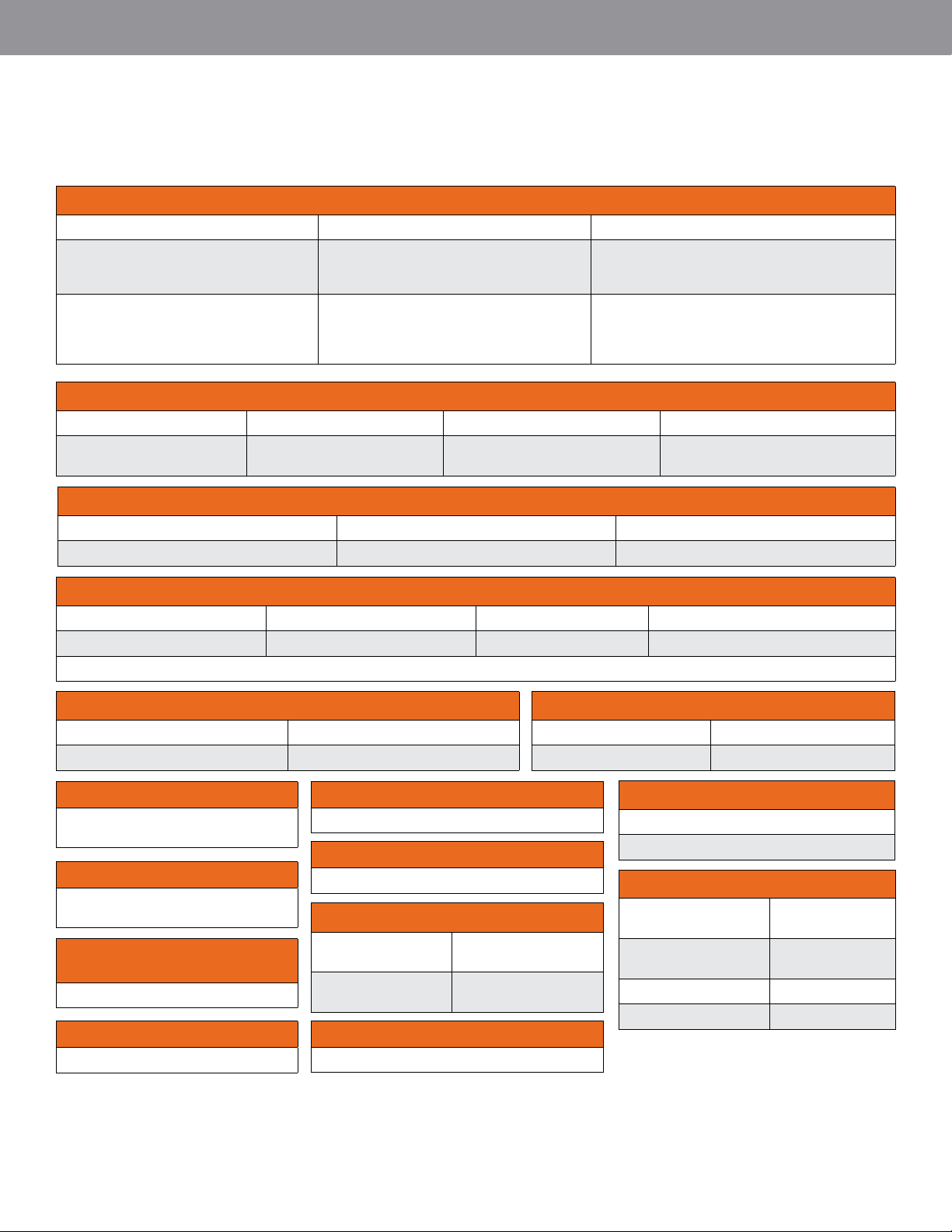
AQUALAB 3 SYSTEM SPECIFICATIONS
POWER REQUIREMENTS
20 GPM (75 LPM) 5 HP Grundfos pump 40 GPM (150 LPM) 7.5 HP Grundfos pump Air-actuated valves
230V / 3PH / 60Hz / 13.2A
460V / 3PH / 60Hz / 6.2A
230V / 3PH / 60Hz / 20A
460V / 3PH / 60Hz / 9.1A
24 VDC
Node converts all voltage signals, but only one
control voltage type can be used per node
230V: Recommended for use
with 20A breaker
460V: Recommended for use
with 15A breaker
230V: Recommended for use
with 30A breaker
460V: Recommended for use
with 30A breaker
WATER INLET LINES
20 GPM (75 LPM) Grundfos pump 40 GPM (150 LPM) Grundfos pump
1” ID 2” ID
SPACE REQUIREMENTS (DEPTH X WIDTH X HEIGHT)
Main Disconnect Box Additional Small Disconnect Box Alfred Gateway
7.5” x 14” x 12” (19.1 x 35.6 x 30.5 cm) 4” x 5” x 8” (10.2 x 12.7 x 20.3 cm) 4” x 7” x 7” (10.2 x 17.8 x 17.8 cm)
SPACE REQUIREMENTS (DEPTH X WIDTH X HEIGHT)
40 GPM Grundfos pump 20 GPM Grundfos pump Aqua-Lab 3 panel (w/o VersaDial) Aqua-Lab 3 panel (w/ VersaDial)
26” x 18” x 39”
(66.0 x 45.7 x 99.1 cm)
14” x 24” x 48”
(35.6 x 60.9 x 121.9 cm)
8” x 32” x 24”
(20.3 x 81.3 x 60.9cm)
8” x 32” x 41.39”
(20.3 x 81.3 x 105.1cm)
OPERATING WATER PRESSURE
200 PSI (14 bar) factory set
(Assumes 40 PSI (2.8 bar) city feed)
MAX. WATER SOURCE TEMP.
Recommended 110°F (43°C)
(Max. water temp.) 180°F (82.2°C)
AIR INLET LINE
3/8” OD Poly Tube per panel
WATER FILTRATION
(SUGGESTED)
50 Micron
AIR OUTLET LINE
3/8” OD Poly Tube per application
AIR INLET PRESSURE
20 CFM @ 80-120 PSI (5.5-8.3 bar) Dry Air
BACK ROOM AMBIENT AIR TEMP
MAX: 130°F (54°C)
SOLUTION OUTLET LINES
Up to 2.25 GPM (8.5 LPM) 3.25 - 4.5 GPM (13.3 - 17 LPM) 5.5 GPM (20.8 LPM) 8.0 - 15.0 GPM (37.9 - 56.8 LPM)
3/8” ID (1/2” OD Poly Tube*) 1/2” ID* 5/8” ID* 3/4” ID
*Assuming line length is 50’ (15 m) or less. Refer to page 42 for recommended size chart for other lengths of tubing.
OUTLET CONNECTION FROM MANIFOLD
20 GPM pump 40 GPM Grundfos pump
1” FNPT 1” FNPT
WATER SUPPLYMAX FLOW PER PORT
Max flow per MAM
valve port 6 GPM
Max flow per BAM
valve port 15 GPM
FLANGE TORQUE
40 GPM Grundfos pump
40 ft-lbs (Min.)
PRESSURE TRANSDUCER (VFD)
Pressure range (20
GPM) 0-300 PSI
Pressure range (40
GPM) 0-363 PSI
Set point 200 PSI
Cord length 23 feet / 7 meters

www.SonnysDirect.com | 5
INSTALLATION INSTRUCTIONS
WHO TASK EST. TIME
DISTRIBUTOR MONITOR & RECORD PERFORMANCE 2 HR / WK
DISTRIBUTOR MAINTENANCE PER SCHEDULE OR AS NEEDED
POST INSTALLATION
TOTAL HOURS SPENT
INSTALLATION
TOTAL CUSTOMER 1 HR
TOTAL DISTRIBUTOR/TECHNICIAN 15 HR
TOTAL ELECTRICIAN 4 HR
TOTAL PLUMBER 4 HR
PRE-INSTALLATION
WHO TASK EST. TIME
DISTRIBUTOR & CUSTOMER DETERMINE LOCATION TO INSTALL EQUIPMENT 1 HR
PLUMBER INSTALL WATER SUPPLY LINE 4 HR
ELECTRICIAN INSTALL ELECTRICAL SUPPLY LINE 4 HR
TECHNICIAN LABEL ALL CONTROLLER RELAYS AT CONTROLLER 1 HR
TECHNICIAN RUN SOLUTION AND AIR LINES (IF NECESSARY) 5 HR
TECHNICIAN INSTALL AIR SUPPLY LINE 1 HR
TOTAL LABOR HOURS 16 HRS
WHO TASK EST. TIME
DISTRIBUTOR / TECHNICIAN HANG EQUIPMENT 1 HR
TECHNICIAN CONNECT WATER, AIR AND SOLUTION LINES 1 HR
TECHNICIAN CONNECT CONTROL LEADS TO MAIN CONTROLLER OR JUNCTION BOX 2 HR
DISTRIBUTOR/TECHNICIAN STARTUP (INJECTOR, METERING TIP AND NOZZLE SELECTION) 3 HR
DISTRIBUTOR/TECHNICIAN DOCUMENT CONFIGURATION 1 HR
TOTAL LABOR HOURS 8 HRS
Installation takes approximately ONE day. An
electrician and a plumber are needed for half a day.
General Skill Level
• Mechanical: Basic - mounting equipment
• Electrical: Advanced - three-phase power and controls knowledge (local codes knowledge required)
• Plumbing: Moderate - principal supply line required
• Pneumatic: Basic - pneumatic utility connection required
• Chemical Knowledge: Moderate - chemical titrations required
ESTIMATED INSTALLATION TIMELINE

6 | © Sonny’s CarWash Backroom by Hydra-Flex, Inc. 2022
INSTALLATION INSTRUCTIONS
STEPBYSTEP INSTALLATION INSTRUCTIONS
NOW ON YOUTUBE!
Scan the QR code to watch our team walk you through
step-by-step instructions.
• Drill with Phillips head
• Concrete drill bit 1/2”
• Concrete drill bit 3/16”
• Hammer
• Hammer Drill
• Utility knife
• Wire stripper
• Socket set
• Tape measure
• Utility knife
USEFUL TOOLS:
• Multi Meter
1. UNPACKING
• First, do NOT discard your manual. We recommend
keeping it in the blue envelope we have provided for you
and store it safely in your wash’s office for troubleshooting
and future references on system maintenance.
• KEEP all accessories shipped in a central and safe
location for installation, after the panel and pump
have been mounted.
• Unpack your system and pump from their
respective boxes.
• Inspect the shipment for any damage or missing
components. Please call us immediately at 952-808-3640 if
either occurs.
• If pumps are included with order, utilize proper lifting
technique and mechanical assistance if necessary.
TOOLS & EQUIPMENT NEEDED:
STEP-BY-STEP FULL INSTALLATION
INSTRUCTIONS
The following pages include all necessary steps to ensure your new Aqua-Lab 3
system and Alfred platform are fully installed for your wash.

www.SonnysDirect.com | 7
INSTALLATION INSTRUCTIONS
2. LOCATION LAYOUTS & MOUNTING
• If location has not been identified during the Pre-Installation Process, make sure to consider the
system’s proximity to feed water, power supply, and the control cabinet, as well as space near the system
to store chemical containers.
*Please note: hoses off the pump are only 6 feet and mounting locations should be planned
for accordingly.
• The following layout options include different ways to install your selection of pumps and panel systems.
2 PANELS, 1 20GPM GRUNDFOS PUMP
** The same layout
can be used with a
40 GPM Grundfos
pump.
***Pump congura-
tion will vary de-
pending on specic
order options.
10
28
41
28
41
14
12
85 Total Width
5
8
6
6
15
8
8
10
3
17
28
27
52
44
4/1/2021
Disconnect
Box
Alfred
Gateway
Aqua-Lab 3
Panel
Primary Air
Regulator
MAM
Position
20 GPM
Wall Mount
20 GPM
Pump
BAM
Position
14”
12”
3” 6”
8”
5”
6” 8” 28”
41”
52”
8”
17”
15”
28”
44”
10”10”
85” Total Width
28”
41”
27”

8 | © Sonny’s CarWash Backroom by Hydra-Flex, Inc. 2022
INSTALLATION INSTRUCTIONS
10 14 10
28
41
28
41
14
12
108 Total Width
5
8
6
6 15
8
4
5
52
44
3/30/2021
28
41
28
41
14
12
85 Total Width
5
8
6
6
8
8
3
17
28
27
9
13
5
7
27 10 10
52
4/1/2021
2 PANELS, 1 40GPM GRUNDFOS PUMP
2 PANELS, 2 20GPM GRUNDFOS PUMPS
41”
27” 10”
10” 14” 10”
28”
17”
12”
3”
9”
10” 52”
52”
44”
41”41”
28”28”
41”
28”
28”
27”
13”
14”
5” 5”
6”
6”
8” 8”
8”
7”
85” Total Width
108” Total Width
8”
15”
12” 8”
6”
5”
4”
5”
6”

www.SonnysDirect.com | 9
INSTALLATION INSTRUCTIONS
28
41
28
41
14
12
5
8
6
6
8
3
17
28
27
9
13
5
7
27
10 10
10
10
142
52
4/1/2021
Additional
Disconnect
Box
3. PUMP INSTALLATION
• There are two types of pumps you can install with your system.
• The Grundfos 20 GPM is wall-mounted. Position it on the wall between 10” and 6’ from your
system to the water supply, using the supplied hose. If needed, purchase our hose extension kit
(part number 1003233) to allow further distance.
• The Grundfos 40 GPM is floor-mounted. Position it on the floor between 10” and 6’ from your
system to the water supply, using the supplied hose. If needed, purchase our hose extension kit
(part number 1003233) to allow further distance.
• The following pages include step-by-step instructions for your specific Grundfos pump installation.
PUMP PRIMING INSTRUCTIONS FOR THE 40GPM GRUNDFOS PUMP
WARNING: FAILURE TO PRIME PUMP WILL VOID WARRANTY
1. Confirm the inlet water source is turned on and the ball valve to the panel
inlet is closed.
2. Loosen the vent plug on the pump head to allow any air that may be trapped in
the pump to escape.
3. Turn on any function from Motor Control Unit to activate pump and run for 2
minutes, then close vent cap (DO NOT OVERTIGHTEN) and turn off pump.
4. Check for any leaks in the plumbing during this time.
NOTE: Some water will spray out of vent cap, so we recommend having a
bucket handy.
5. Open ball valve to Aqua-Lab 3 manifold inlet.
3 PANELS, 2 20GPM GRUNDFOS PUMPS
142” Total Width
28”
10” 10” 10”
10”
52”
8”
28”
27”
27”
12”
3”
9”
13”
14”
5” 5”
4”
6”
6”
8”
8”
7”
41” 28”
17”

10 | © Sonny’s CarWash Backroom by Hydra-Flex, Inc. 2022
INSTALLATION INSTRUCTIONS
20 GPM GRUNDFOS WITH INTEGRATED VFD CONT.
952-808-3640 • www.hydraexinc.com
20 GPM GRUNDFOS WITH INTEGRATED VFD
INSTALLATION INSTRUCTIONS
33”
29”
44”
44”
26”
11”
Top Of Pump
Mount
Main Water Inlet
RevD0422_4000230

www.SonnysDirect.com | 11
INSTALLATION INSTRUCTIONS
952-808-3640 • www.hydraexinc.com
20 GPM GRUNDFOS WITH INTEGRATED VFD
INSTALLATION INSTRUCTIONS
STEP 4
STEP 2
STEP 1
Locate your inlet lter, remove the lter bowl, and attach
to the bottom of the pump. Once the inlet lter is tight,
re-attach the lter bowl until it’s hand-tight. Once
tightened re-attach the lter bowl hand tight.
STEP 3
Next you’ll need to secure your pump to the wall mount
bracket using the (4) provided nuts and bolts.
Next you will need to secure your pump to the mount. Lift
and rest pump on the back of the bracket attached to the
wall, then attach the front bracket to wall bracket using
hardware provided.
If attaching your pump to a concrete wall: Decide where
you want your pump to be located and secure to wall using
concrete anchors. (Make sure to check that all wiring and
plumbing will work with the location of the pump before
securing to the wall.)
If attaching your pump to a wall with studs: Decide
where you want your pump to be located and attach (2) 4’
2” x 4” to three studs using 3-4” lag bolts and mount pump
bracket onto the 2x4s.
PLUMBING BOX(ES)
Contains: Inlet Filter Plumbing Kit.
PLUMBING BOX(ES)
Contains: (1) Plug. Note all of these parts may not be
needed depending on your system conguration.
RevD0422_4000230
20 GPM GRUNDFOS WITH INTEGRATED VFD

12 | © Sonny’s CarWash Backroom by Hydra-Flex, Inc. 2022
INSTALLATION INSTRUCTIONS
PLUMBING BOX(ES)
Contains: Inlet Filter Plumbing Kit.
STEP 2
STEP 4
STEP 3
STEP 1
952-808-3640 • www.hydraexinc.com
40 GPM GRUNDFOS WITH INTEGRATED VFD
INSTALLATION INSTRUCTIONS
Identify the ow direction of the pump by locating the
arrow on the base of the pump (It should come in the front,
the side with the VFD). Using the Inlet Plumbing Box 1,
thread in part A and tighten. Then place rubber gasket in
the groove on part A.
Connect main water inlet hose to lter inlet and secure
using pipe clamps provided (or hard plumb into lter).
Connect the lter to part A from step 1 using the provided
retention clamp and tighten together.
Locate where you want your pump to be located and
secure to oor using concrete anchors. (Make sure to check
that all wiring and plumbing will work with the location of
the pump before securing to the ground.)
PLUMBING BOX(S)
Contains: (1) Outlet Manifold, (2) Elbows, and (1) Plug.
Note all of these parts may not be needed depending on
your system conguration.
A
4000231_RevF0422
40 GPM GRUNDFOS WITH INTEGRATED VFD

www.SonnysDirect.com | 13
INSTALLATION INSTRUCTIONS
40 GPM GRUNDFOS WITH INTEGRATED VFD CONT.
952-808-3640 • www.hydraexinc.com
40 GPM GRUNDFOS WITH INTEGRATED VFD
INSTALLATION INSTRUCTIONS
STEP 6
STEP 6.1
If using pump with an Aqua-Lab XD Gen2 or HD system,
thread panel inlet hose into the manifold and tighten.
If using pump with only one panel, thread in plug to the
opening in pump manifold and tighten.
STEP 5
Thread outlet manifold into the outlet of the pump and
tighten until the manifold is oriented as shown in Photo 1.
PHOTO 1
4000231_RevF0422
STEP 8
Connect pump to electrical supply.
STEP 7
Remove (3) plugs from pump.

14 | © Sonny’s CarWash Backroom by Hydra-Flex, Inc. 2022
INSTALLATION INSTRUCTIONS
952-808-3640 • www.hydraexinc.com
40 GPM GRUNDFOS WITH INTEGRATED VFD
INSTALLATION INSTRUCTIONS
STEP 9
STEP 10
Open ball valve to Aqua-Lab manifold inlet.
4000231_RevF0422
WARNING:
FAILURE TO PRIME PUMP WILL VOID WARRANTY
1. Confirm the inlet water source is turned on and the
ball valve to the panel inlet is closed.
2. Loosen the vent plug on the pump head to allow any
air that may be trapped in the pump to escape.
3. Turn on any function from Motor Control Unit to
activate pump and run for 2 minutes then close vent
cap (DO NOT OVERTIGHTEN) and turn off pump.
4. Check for any leaks in the plumbing during this
time.
NOTE: Some water will spray out of vent cap, so we
recommend having a bucket handy.
5. Open ball valve to Aqua-Lab manifold inlet.
40 GPM GRUNDFOS WITH INTEGRATED VFD CONT.

www.SonnysDirect.com | 15
INSTALLATION INSTRUCTIONS
4. PANEL INSTALLATION
• We highly recommend mounting your main panel 32” from floor to the base of the panel for easy
injector access.
• For easier installation, remove the door during install. Be sure to replace door when finished
mounting the panel.
• Refer to the layout drawings on pages 7-9 for multiple system panel configuration
recommendations.
• Tip: Mount the VersaDial panel first. It sets the low point of the entire system to ensure room for the
chemicals below the panel. This aids in allowing support for the main panel install by letting the
main panel rest on the VersaDial attachment as you mark the drill points.
Aqua-Lab 3 WITH VERSADIAL PANEL (WALL MOUNT)
• Drill (6) 3/16” holes in wall in the following locations (see picture)
• Press Aqua-Lab 3 board tight against the wall.
• Screw in 1/4” concrete screws with a washer.
5. PNEUMATIC CONNECTIONS
• Connect pre-run 3/8” OD poly feed line to push connect fitting on the
side of the primary regulator (or as required).
• Connect 3/8” OD poly lines from arch to each port that will be foaming
6. ALFRED GATEWAY AND DISCONNECT
BOX CONNECTIONS
• Disconnect Box - Mount to the wall with 4 appropriate anchors. (see the
drawing above)
• Alfred Gateway - Mount to the wall with 4 appropriate anchors. (see the
drawing above)
10
28
41
28
41
14
12
85 Total Width
5
8
6
6
15
8
8
10
3
17
28
27
52
44
4/1/2021
Disconnect
Box
Alfred
Gateway
Aqua-Lab 3
Panel
Primary Air
Regulator
MAM
Position
20 GPM
Wall Mount
20 GPM
Pump
BAM
Position
14”
12”
3” 6”
8”
5”
6” 8” 28”
41”
52”
8”
17”
15”
28”
44”
10”10”
85” Total Width
28”
41”
27”

16 | © Sonny’s CarWash Backroom by Hydra-Flex, Inc. 2022
INSTALLATION INSTRUCTIONS
Blue Indicator light
the pump is on
Green light behind these
valve position is on
24DC Power
Cable (input)
Home Run
Cable with
Quick Connect
(input)
Air 80-120
PSI (input)
Air to MAM
& BAM valve
(output)
White light indicator behind
is on
Data Line Cable from Alfred Gateway
has one connection in and one
connection out and then from here
goes to the next panel or pump.
Always ending with the pump. (output)
Mode Indicator Light
Valve Port 7: Brown
Valve Port 6: Red
Valve Port 5: Orange
Valve Port 4: Yellow
Valve Port 3: Green
Valve Port 2: Blue
Valve Port 1: Purple
Common/GND: Black
See right for
input/output wire setup
Home Run Cable to MCC
7. ELECTRICAL CONNECTIONS
There are 5 primary electrical connections and wiring cables that you need to be conscious about directional
placement and plugins when setting up your new system. We recommend installing the cables in the order
listed below.
1. Ethernet Cable – A standard Ethernet (Cat 5, 5e or 6) cable powers the internet to your Alfred Gateway.
We recommend you run this cable from your network to the Gateway installation location prior to
beginning the Aqua-Lab 3 installation.
2. Home Run Cable – This cable with quick connect from node supports the signals that run to the car
wash control panel or the MCC. Each manifold position below designates which
Valve Port is associated to what color wire and home run cable length. *Node
converts all voltage signals, but only one control voltage type can be used per node
Example: if you want Presoak 1 to be on Valve Port 6, connect the
red wire to your controller relay for Presoak 1.
3. 3 Phase Site Voltage – Have certified electrician land 3 Phase Site Voltage
4. 3 Phase Power Cable – This cable provides power to the pump. It has a quick connect
to the bottom port on the Disconnect Box and is wired directly to the pump.
5. 24DC Power Cable – This cable provides power to the Alfred Gateway and the Node
Technology in the panels. This cable is 3 meters (9’10”) in length, if needed you can
daisy chain anywhere between 3-4 cables depending on how many panels you have.
Always start this cable at the Disconnect Box, then run one cable to Alfred Gateway,
and the other cables through to the node.
6. Data Line Cable – This 3 meter (9’10”) cable connects the Alfred Gateway to the
panels and the pump to provide the data signals of information. This cable always
needs to start at the Gateway and end at a pump.
On the following pages you will find wiring diagrams for all 5 electrical connections listed
above and for each system configuration possible.
VALVE PORT WIRING

www.SonnysDirect.com | 17
INSTALLATION INSTRUCTIONS
Blue Indicator light
the pump is on
Green light behind these
valve position is on
24DC Power
Cable (input)
Home Run
Cable with
Quick Connect
(input)
Air 80-120
PSI (input)
Air to MAM
& BAM valve
(output)
White light indicator behind
is on
Data Line Cable from Alfred Gateway
has one connection in and one
connection out and then from here
goes to the next panel or pump.
Always ending with the pump. (output)
Mode Indicator Light
Valve Port 7: Brown
Valve Port 6: Red
Valve Port 5: Orange
Valve Port 4: Yellow
Valve Port 3: Green
Valve Port 2: Blue
Valve Port 1: Purple
Common/GND: Black
WIRING DIAGRAMS
Node Power Cable
(24 VDC)
(Can be gray or black)
Data Line
Cable
(Modbus)
3 Phase Power Cable
(Black cable comes from the
main supply & the gray is the
quick connect to the pump)
24VDC 4A
230/460V
3 PHASE
SITE VOLTAGE
DISCONNECT
BOX W/ POWER
START
1
23
END
ALFRED
GATEWAY
MCC
Ethernet Cable
3 Phase Power Cable
24 DC Power Cable
Data Line Cable
Home Run Cable
2 PANELS, 1 PUMP
CRITICAL STEP
You MUST start Data Line Cable at the Alfred Gateway. The Data Line Cable then connects to the in port
on the first panel. The digital Gateway setup configuration must be completed before EACH cable is
connected. Connect the next cable to the out port of the next panel’s in port. Continue for remainder of
panels ending with the pump.

18 | © Sonny’s CarWash Backroom by Hydra-Flex, Inc. 2022
INSTALLATION INSTRUCTIONS
Ethernet Cable
3 Phase Power Cable
24DC Power Cable
Data Line Cable
Home Run Cable
24VDC 4A
230/460V
3 PHASE
SITE VOLTAGE
DISCONNECT
BOX W/ POWER
START
1
23
END
ALFRED
GATEWAY
MCC
24VDC 4A
230/460V
DISCONNECT
BOX W/ POWER
START
1
2
END
MCC
ALFRED
GATEWAY
3 PHASE
SITE VOLTAGE
CRITICAL STEP
You MUST start Data Line Cable at the
Alfred Gateway. The Data Line Cable then
connects to the in port on the first panel.
The digital Gateway setup configuration
must be completed before EACH cable
is connected. Connect the next cable to
the out port of the next panel’s in port.
Continue for remainder of panels ending
with the pump.
1 PANEL, 1 PUMP
2 PANELS, 1 PUMP

www.SonnysDirect.com | 19
INSTALLATION INSTRUCTIONS
24VDC 4A
DISCONNECT
BOX W/ POWER DISCONNECT BOX
(for added pump)
230/460V
START
1
2 3
4
5
END
MCC
ALFRED
GATEWAY
3 PHASE
SITE VOLTAGE
3 PHASE
SITE VOLTAGE
24VDC 4A
START
1
2
3
4
END
230/460V
DISCONNECT
BOX W/ POWER DISCONNECT BOX
(for added pump)
MCC
ALFRED
GATEWAY
3 PHASE
SITE VOLTAGE
3 PHASE
SITE VOLTAGE
3 PANELS, 2 PUMPS
2 PANELS, 2 PUMPS

20 | © Sonny’s CarWash Backroom by Hydra-Flex, Inc. 2022
INSTALLATION INSTRUCTIONS
INITIAL INJECTOR SETUP
(Based on field experience this is Sonny’s Backroom’s recommended starting point)
1. Using the recommended starting point (Page 38) or the target flow rate and the chemical dilutions
chart (appendix Page 40 for VersaDial) install the appropriate injector into each port.
2. Connect pre-run solution lines to each injector with the supplied coupler and push connect fitting.
a. Be sure to use Teflon tape when connecting the injector to the coupler and push connect
fitting to ensure there are no leaks.
b. Do not overtighten poly fittings or they may crack.
3. Connect ¼” poly lines from each chemical container to the
hose barb on the appropriate injector or VersaDial.
a. Ensure a foot valve or similar check valve/filter is
installed on each line.
b. These must be present or metering tips may clog.
4. Metering tips or VersaDial will need to be installed to set
dilution ratio (see appendix Page 40 for ratio charts to
determine tip or dial setting.) *this step needs to be done if not using the VersaDial Metering
Control System
If there are unused air ports, turn the individual line regulator counter-clockwise until air no longer flows.
TRIPLE FOAM SETUP
Your Aqua-Lab 3 panel was designed with Tri-Foam
capability. These instructions will teach you how to set
up your triple foam.
• Your triple foam has been set up from the
factory to be in the rst port on the far left. (See A)
• Insert your triple foam manifold into that position
with your selected injectors already inserted.
• On the top of the panel, the regulators will control
the air to each of your triple foam colors.
• Insert your air lines to the arch into the bulkhead
ttings on the top of the panel. The bulkhead will
be the air lines for each color.
Note: Occasionally, if all three regulators are
pre-set too high, you may need to lower all three
regulators to their lowest setting and then turn
them up to the desired pressure.
8. SOLUTIONS CONNECTIONS
A
A
B
B
C
C
Table of contents
Other Hydra-Flex Dispenser manuals