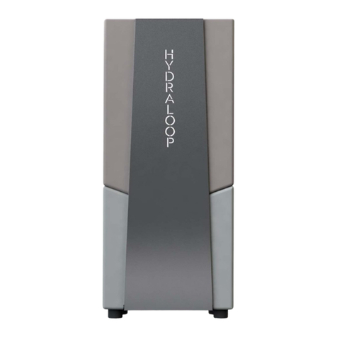
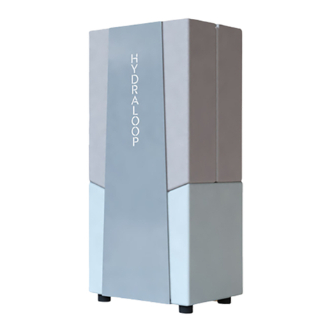
HYDRALOOP H300 Guide

Hydraloop Home, Garden & Pool
User & installation manual
V3.5 2020
Hydraloop User & Installation Manual
1

Contents
1. Introduction 3
2. Product definition 4
3. Transportation 5
4. Installation considerations 5
5. Plumbing 7
6. Initial starting up of Hydraloop unit 16
7. Period of ‘non activity’ 18
8. Electric power cut 18
9. Mains water backup 18
10. System malfunction 19
11. Explanation of LED lighting 19
12. Warranty 21
13. Frequently Asked Questions 21
14. Limitations 23
15. Certification 24
16. Specifications 26
V3.5 2020
Hydraloop User & Installation Manual
2

1. Introduction
Hydraloop Systems B.V. offers a range of products which can be used for recycling domestic
greywater. With the use of these products home-owners can save 45% of their mains water by
recycling up to 85% of their mains water consumption. With a Hydraloop installed, a 4-person family
can also save up to the equivalent of + 600kWh/year in energy and reduce up 476kg/year CO2
emission or 6,3% of total in-house CO2emission. Hydraloop’s recycled water is clean, clear, safe,
disinfected and certified.
With a Hydraloop unit installed up to 95% of shower and bath water can be recycled. Greywater from
the washing machine is only allowed to enter the Hydraloop unit in combination with the additional
Hydraloop washing machine recycle option. If the washing machine recycle option is installed, an
additional 50% of the washing machine water can be recycled.
•The definition of mains water is water provided by mains, city water or tap water supply.
•Note: Hydraloop units can only accept greywater from shower, bath and optionally the washing
machine and cannot accept greywater from hand basins, dishwashers or the kitchen sink and t is
not allowed to feed the Hydraloop unit with water from these sources.
•This document describes the operational functionality of the units and specific information
regarding design guidelines and installation. Instructions for architects and contractors are
covered by separate documents provided by Hydraloop Systems B.V..
In countries with cooler climates energy can be saved by the Hydraloop unit in autumn, winter and
spring, when the unit is installed inside the house, in three ways:
•Shower and bath water entering the Hydraloop unit still has a temperature of + 32 degrees C. The
Hydraloop unit radiates the remainder of this warmth until it ia reduced to ambient temperature.
•The washing machine uses Hydraloop’s recycled water which is at ambient temperature of + 20
degrees C. Mains water has a temperature between 8-12 degrees C and to heat this to 40 degrees
C uses more energy than to heat Hydraloop’s recycled water from 20 to 40 degrees C.
•With a Hydraloop unit toilets do not import cold mains water after flushing - with a temperature of
between 8-12 degrees C inside the house - but use recycled water with an ambient temperature of
+ 20 degrees C.
The total energy saving for a 4-person family is the equivalent of + 600 kWh/year. The Hydraloop
itself uses + 200 KwH/year so the net energy saving is + 400 kWh/year.
V3.5 2020
Hydraloop User & Installation Manual
3

2. Product definition
The Hydraloop product range:
•Hydraloop H300 Garden or Pool
•water recycling from shower and bath water with 1 valve controlled outlet to pump recycled
water to either a (rain)water tank in the garden or to top up the (swimming)pool.
•Hydraloop H300 Home
•water recycling from shower and bath water with 2 water outlets. 1 outlet to feed the toilet
cisterns and a second one for feeding the washing machine. The unique Hydraloop water
sensor technology* offers the washing machine to use recycled water for the first 2 cycles and
will switch to backup water for the 3rd cycle and 4th cycle if applicable).
•Optional garden/pool outlet
•adding this third outlet to the Hydraloop Home unit to pump recycled water to either a
(rain)water tank in the garden or to top up the (swimming)pool.
•Optional washing machine recycle option*
•depending on the chosen washing machine program + 50% of the washing machine water is
recycled back into the Hydraloop unit via its own sanitary liftpump
*Patents pending
Greywater from bath and shower enters the Hydraloop unit via gravity or via a sanitary liftpump* if the
unit is based on the same level as the bathroom. The distribution centre of the Hydraloop unit pumps
its recycled water to multiple toilets. It can distribute recycled water to 4 toilets with a maximum
height of 11m above the Hydraloop unit.
*We recommend a DAB Novabox or Genix VT030. It is important that the pressure tube from the lift pump is
32mm to avoid excessive flow of water entering the Hydraloop unit.
Note: Make sure you mount the special white floater arm that comes with the Novabox and
Genix VT sanitary liftpump, so that the stand-by water level in the sanitary liftpump is at low
level (https://dabpumps.com/en).
The washing machine water recycle option consists of additional sensors and software to monitor
when the washing machine is taking water from the Hydraloop unit. A washing machine program
takes water between 3 - 5 times, depending on the washing machine program. Water from the first
two washing cycles from the washing machine can be very dirty. Therefore the Hydraloop unit
equipped with the extra washing machine recycle option will not accept these first batches of
greywater for recycling. The Hydraloop unit controls the liftpump that lifts the washing machine water
into the Hydraloop and switches the lift pump temporarily off. The first two cycles of greywater will
bypass the Hydraloop system directly to the sewer. When the washing machine takes water for the
third washing cycle, the system senses this and will switch the lift pump back on. Greywater from the
washing machine from the third, fourth and fifth cycle (depending on which washing machine
program is chosen) will all be pumped back into the Hydraloop unit and will be recycled.
All the above is done fully automatic by the Hydraloop unit and works with any consumer washing
machine brand.
V3.5 2020
Hydraloop User & Installation Manual
4

Limitations: Maximum 60 degrees C washing program is allowed. >60 degrees C washing
program is not allowed as it can seriously damage the Hydraloop unit and its sanitary lift pump.
Note: Only a Hydraloop unit equipped with an additional washing machine recycle option has
the hardware and software to receive and treat greywater from the washing machine.
3. Transportation
The Hydraloop unit will be transported to your location mounted and
strapped onto a transportation plate, wrapped in protective foil and
mounted onto a pallet. When moving the Hydraloop unit it is important to
always keep it in an upright, vertical position. Bringing the Hydraloop unit Into a horizontal position
may cause damage to its internal components and seals. It is very important to handle the Hydraloop
with great care and to leave the protective foil on until it is placed at its final installation position.
After it is removed from the wooden pallet leave it
strapped on the transportation plate and the unit
can be moved with a 2-wheel trolley. Only when it
is near its final position then remove the foil and
carefully lift the unit from the plate and place it at
its final position.
4. Installation considerations
Hydraloop units can be installed in many different
locations in or around the house but are not
allowed to be positioned in direct sunlight. It is
not allowed to install the unit outside the house
when it isn’t covered from rain or direct sunlight
and temperatures should stay within the limits of
+14 and +35 degrees C.
The initial startup of the Hydraloop unit can only
be done with an active local wifi network. We strongly recommend - in case of new build - not to
install and start up the Hydraloop unit during the building process but only after the house is fully
ready and all works are finished. At all times please avoid
that building dirt, chemicals or sand can enter into the
Hydraloop unit as it will damage the Hydraloop unit.
Each installation will have its own circumstances but ideally
a Hydraloop system should be located so that water flows
into the Hydraloop system by gravity. For example placing
V3.5 2020
Hydraloop User & Installation Manual
5

a Hydraloop system on the ground floor with a greywater gravity feed from the bath/shower from the
first floor. If the Hydraloop system is on the same level as the shower/bath an appropriate* liftpump
has to be installed to lift the water from the shower/bath up into the Hydraloop system.
*We recommend a DAB Novabox or Genix VT030. It is important that the pressure tube from the lift pump is
32mm to avoid excessive flow of water entering the Hydraloop unit.
If a Hydraloop unit is installed with the extra washing machine recycle option, the ideal place for
installation would be close to the washing machine, so that the washing machine liftpump can be
placed next or close to the washing machine. If the washing machine is placed on the same floor as
the Hydraloop but in another room, the lift pump can be installed close to the washing machine and
the greywater is lifted up, and from there flows into the Hydraloop unit.
Note: It is not allowed to combine one lift pump for both the washing machine recycle option
and the shower/bath water.
The liftpump must be placed so that it is easily
accessible for maintenance. A 230 volt wire with
ground connection should be installed from the
Hydraloop unit to the washing machine liftpump
so the lift pump will receive power supply from
the Hydraloop unit and can be switched on/off.
Note: It is very important that the washing
machine lift pump is installed ‘in line’ with the
sewer, in such a way that the waste water can
go to the sewer via the overflow in the
liftpump, in case the lift pump is switched off
by the Hydraloop unit. The washing machine
lift pump is controlled by the software of the
Hydraloop unit. The unit will fully
automatically temporarily switch the liftpump
off so it will not receive the waste water from
the first two washing cycles. In this case the
bypass within the liftpump will release the
waste water to flow directly to the sewer.
The recycled water output from the Hydraloop
system can feed up to 4 toilets. It is advisable to integrate an expansion vessel somewhere in the the
line that feeds the lavatories. A second Hydraloop outflow valve feeds the washing machine. The
Hydraloop unit can have a third valve controlled water output which can supply recycled water to the
garden or pool.
V3.5 2020
Hydraloop User & Installation Manual
6
mains electrical
connection
waste water to sewage
pumped feed to lavatories
pumped feed to
pumped feed
to washing
machine
greywater input
wifi connection
mains backup water
on/off
lift pump
on/off
WM recycle option

5. Plumbing, basic rules
•Use shower & bath water as source water and optionally washing machine water in case a
Hydraloop washing machine recycle option is installed. No washbasins, kitchen sinks &
dishwasher may be connected!
•Before connecting the back up mains water supply to the Hydraloop unit, first let this
water run for some time to flush sand and dirt out of the mains water tube before
connecting it to the Hydraloop unit. If sand or dirt enters the Hydraloop unit this will damage
the the internal pump and valves.
•Connect all incoming greywater pipes into a single 75/50/40mm pipe into the 40mm inlet on
the top of the Hydraloop unit.
•On the low side of the Hydraloop, for connecting the recycled and treated water:
•use the left hand ½” flex hose and connect to the tube that feeds all toilets
•use the right hand ½” flex hose and connect to the washing machine, and
•In case of a Hydraloop Pool/Garden, use the single ½” flex hose and connect to the tube
that feeds the garden rainwater tank or feeds the pool
•Label everything. Use color coded pipe or warning labels on the pipe to designate that the
pipes are running recycled water
•Hydraloop has a built in overflow facility
•Install appropriate overflow at the sanitary liftpumps to avoid flooding the systems
•Standard plumbing practice should be performed. The 75/50/40 mm greywater feed tube
from the shower/bath needs to have proper ventilation to support shower water flowing
without airlocks to the Hydraloop unit. Also sewer venting is necessary to ensure proper
functioning of the Hydraloop unit.
•With the washing machine recycle option installed, the wastewater tube from the washing
machine needs to be"fed into the Hydraloop system via its sanitary liftpump. Even in the
event the washing machine is installed on a floor above the Hydraloop unit, the water still
needs to be fed via the liftpomp - controlled by the Hydraloop unit - with an overflow to the
sewer. The sanitary liftpump receives 230 volt grounded current from the Hydraloop unit and
is switched on/off by the Hydraloop unit. The overflow is used to discharge the first 2 washing
cycles to the sewer when the liftpump is switched off.
Overview of Hydraloop plumbing options (see drawing on next page)
•A. Greywater flows by gravity from shower & bath on 1st floor to the Hydraloop unit on the ground
floor.
•B. Greywater is lifted up using a liftpump* from shower & bath on ground floor to the Hydraloop
unit on the ground floor.
*We recommend a DAB Novabox or Genix VT030. It is important that the pressure tube from the lift pump is
32mm to avoid excessive flow of water entering the Hydraloop unit.
•C. Greywater flows by gravity from shower & bath on 1st floor to the liftpump on ground floor to
the liftpump, and is then lifted up into the Hydraloop system.
•D. Shows how the washing machine should be connected via its dedicated liftpump that is
delivered when opting for the extra washing machine recycle option with your Hydraloop unit. The
dedicated washing machine liftpump is powered and controlled by the Hydraloop unit.
Note; assure that appropriate venting is installed as shown on the drawings.
V3.5 2020
Hydraloop User & Installation Manual
7

V3.5 2020
Hydraloop User & Installation Manual
8
DAB Nova Box lifting station!
https://dabpumps.com/en/novabox
Pressure tube
25/32mm
ground floor
shower, bath ground floor
Pressure tube
25mm
1st floor
overflow lift
pump to sewer
Gravity flow grewwater tubes size 75/50/40mm
Pressure tube greywater from liftpomp to Gravity greywater tube
230 volt power from Hydraloop to lift pump
independent feeds recycled water to toilets, washing machine & garden/pool
showers baths 1st floor
To sewer ventilation
OVERVIEW HYDRALOOP PLUMBING OPTIONS !
A. Greywater from shower & bath on 1st floor via
gravity to Hydraloop. !
B. Shower/bath water on ground floor via liftpomp.!
C. 1st floor shower/bath via ground floor & lift pump, !
D. Washing machine via dedicated liftpump
A
B
C
D
Hydraloop input 40mm
230 volt
power for lift
pump from
Hydraloop
To sewer ventilation
Mains water
overflow lift pump to sewer

V3.5 2020
Hydraloop User & Installation Manual
9
Section A-A (Scale 1 : 5)
Mains & Feed Connections in floor
Detail B (Scale 1 : 5)
Alternative Connections from the Backside/Wall
A A
B
© All rights reserved. Reproduction or disclosure of (any part of) this document without exclusive written permission of 3Design Dynamics is not permitted
GENERAL TOLERANCES
ACC. ISO 2768-mK
Drawing No
Engineer
Status
Datum
Scale
Revision :
:
:
:
A3
Units: Projection:
Mass:
D.Y.J. Veenendaal
16-1-2018
LAYOUT CONNECTIONS HYDRALOOP 300-TWG
Sheet: 1 /1
Machine No:
Product Group:Project:
Description:
1 : 20
Assembly Hydraloop
300-Layout Connections
N/A
mm
:
:
DIMENSIONAL
TOLERANCING
ACC.
NEN-ISO 129-1
SURFACE TEXTURES
ACC.
NEN-EN-ISO 1302
GEOMETRICAL
TOLERANCING
ACC.
NEN-ISO 1101
Hydraloop Systems B.V.
+31 (0)6 302 666 16
d.veenendaal@hydraloop.com
www.hydraloop.com
40-50 mm dist. to wall
Waste Water Sleeve Ø75 mm
Feed to Garden / Pool - male thread ½"
Feed to Toilet Cistern (WC) - male thread ½"
Feed to Washing machine - male thread ½"
Mains water supply - male thread ½"
340
(1864)
Pipe and Hose
Connections:
(83)
210
60 60 60
300
225
320
800 (50)
900Install width
2100
Install height mm
Infeed connection
82 (Sleeve Ø75)
260
180
40
25 (4x pipe Ø22)
330
170
22Ø (4x) 40Ø
40 40

Installation and plumbing details
Remove the stainless steel front plate, using for example a large screwdriver, on the low side of the front
plate to lift the stainless plate up. The plate is holding its position due to its shape so once it comes
upwards it will be free to remove. Perform this with care.
Hydraloop Mounting Scheme
Hook the mounting
hole of the
Hydraloop top
plate onto the
screwthumb, which
you should plug
into the wall, so the
Hydraloop is
secured.
Hydraloop waste water system installation
A common
installation
situation is
executed
with the
drain /
discharge
pipe below
V3.5 2020
Hydraloop User & Installation Manual
10
Hydraloop Inlet Scheme & Incoming Water Sensor
1. Place the blue sealing ring first in the top lid infeed channel
2. Install the infeed tube system into the sealing ring with a
minimal amount of grease (Vaseline) applied on the Y-tube end
3. Connect the air release tube in the push-in fitting on the
branch of the Y-tube
4. Connect the solid blue pressure sensor, near the 45° bend
5.Connect the transparent pressure sensor, near the 90° bend

the Hydraloop unit connecting the wastewater outflow to the sewer with core sleeves trough the floor:
!!!!!!!!!!!!!!!!!!!!!!!!!!!!!!!!!!!!!!!
The connection between the inlet wastewater pipe and the (PVC) drain or discharge pipe is established with
the application of an eccentric 75m adapter ring in combination with a 50/40mm reducing rubber sealing
sleeve (not delivered with the Hydraloop system). The bend at the end of the Hydraloop Drain System is
inserted into the rubber sealing sleeve.
"""""""""" """""""""""
PVC Insert Adapter Ring, eccentric!!!!!!! Rubber sleeve
"A limited amount of misalignment can be compensated by rotating the 75m eccentric adapter ring before
glueing it in the 82m tube and/or adjusting the length of the tube between the bend and the T part.
Rotate & adjust
There is enough space to extend the Drain System with a 40 mm tube and guide it between the system and
the floor by replacing the bend with an extension tube or to mount the bend directly into the Tee and orient
it horizontally, for instance, towards the wall behind the Hydraloop or whatever configuration is desired with
V3.5 2020
Hydraloop User & Installation Manual
11

custom fittings. For this, the horizontal drain pipe section can be lowered approx. 6 – 10 mm at the bend
connecting the vertical section to be able to pass underneath the tank.
"
Slightly lower the drain pipe and extend
!
V3.5 2020
Hydraloop User & Installation Manual
12
Connection to
toilets
Connection to
washing machine
Connection to
garden/pool
Mains water
Detail A
Distributiesysteem
Detail B
EB Beveiliging
A
B
© All rights reserved. Reproduction or disclosure of (any part of) this document without exclusive written permission of 3Design Dynamics is not permitted
GENERAL TOLERANCES
ACC. ISO 2768-mK
Drawing No
Engineer
Status
Datum
Scale
Revision :
:
:
:
A3
Units: Projection:
Mass:
D.Y.J. Veenendaal
19-6-2019
SPECIFICATIE AANSLUITING
LEIDINGWATER HYDRALOOP
Sheet: 1 /1
Machine No:
Product Group:Project:
Description:
1 : 17
Assembly Hydraloop-v1
N/A
mm
:
:
DIMENSIONAL
TOLERANCING
ACC.
NEN-ISO 129-1
SURFACE TEXTURES
ACC.
NEN-EN-ISO 1302
GEOMETRICAL
TOLERANCING
ACC.
NEN-ISO 1101
Hydraloop International B.V.
+31 (0)6 302 666 16
d.veenendaal@hydraloop.com
www.hydraloop.com
Aansluiting invoer leidingwater
A.u.K. Müller vlotterkraan
T4 leidingwatertank (backup)
Met overloopbeveiliging
Compartiment is geen luchtdicht afgesloten ruimte
Detail Aansluitschema T4
Detail T4
EB Beveiliging: Watts Ocean Keerklep NN, art.nr. 230015165
Aansluiting
Müller vlotterkraan
AK Muller float valve
In some countries an EB non return valve is mandatory to be installed on
the float valve additional to the air gap back flow protection. Please check
if a Watts Ocean NN non return valve art number 2300151165 is fixed
between the float valve and the flexible tube that is connected to the
mains water supply. If not installed the mains water connection does not
comply with the Kiwa certification.
Important!

Plumbing connections
Input
Greywater into Hydraloop 40mm connections
Mains water 1/2 inch male thread, minimum water flow 20 liters p/m at 2 bar
Output
Waste water to sewer 40mm connection to sewer
Sewer connection 85 to 50mm with rubber manchet
underneath the Hydraloop system (see drawing) or behind
the Hydraloop system into the floor or wall
Recycled water to toilet 1/2 inch male thread
prepare plumbing underneath or behind Hydraloop
system. Connect with flexible tube
Recycled water to w. machine 1/2 inch male thread
prepare plumbing underneath or behind Hydraloop
system. Connect with flexible tube
Recycled water to garden/pool 1/2 inch male thread
prepare plumbing underneath or behind Hydraloop
system. Connect with flexible tube
Differentiation and identification
Differentiation and identification through labelling and marking provides users and maintenance staff
with suitable information to ensure safe operation of the greywater treatment and potable water
distribution system.
To prohibit misuse it is recommended that all non-potable water taps shall be equipped with a safety
device (e. g. detachable lever).
All pipework (both collection and distribution), fittings and points of use for non-potable water
systems shall be marked and labelled to prevent accidental consumption or cross-connection
between the potable and non-potable water and cross-connection between the different collection
pipework:
•Draw-off points for non-potable water shall be identified with the words "Non-potable water"
or by a prohibition sign as shown below.
V3.5 2020
Hydraloop User & Installation Manual
13

Sign "Potable water" (left) and prohibition sign "Non-potable water" (right) according to
EN 806-2
•the pipes of the non-potable water distribution systems shall be clearly identifiable; this can
be ensured by different colour pipes from potable water pipes or by an identification band
with the pipe;
•close to the drinking water mains valve, a sign with a notice of the existence of a non-potable
water system, shall be installed.
Installation / drill template
The drawing below can be used to prepare an installation /drilling template so the the plumbing
connections can be prepared and checked before the Hydraloop unit arrives and will be placed and
installed.
V3.5 2020
Hydraloop User & Installation Manual
14

V3.5 2020
Hydraloop User & Installation Manual
15
Detail A
(Scale 1 : 2.5)
Detail B
(Scale 1 : 2.5)
A
B
© All rights reserved. Reproduction or disclosure of (any part of) this document without exclusive written permission of 3Design Dynamics is not permitted
GENERAL TOLERANCES
ACC. ISO 2768-mK
Drawing No
Engineer
Status
Datum
Scale
Revision :
:
:
:
A3
Units: Projection:
Mass:
D.Y.J. Veenendaal
20-4-2018
INSTALLATION / DRILL TEMPLATE
Sheet: 1 /1
Machine No:
Product Group:Project:
Description:
1 : 5
Assembly Hydraloop-v1
N/A
mm
:
:
DIMENSIONAL
TOLERANCING
ACC.
NEN-ISO 129-1
SURFACE TEXTURES
ACC.
NEN-EN-ISO 1302
GEOMETRICAL
TOLERANCING
ACC.
NEN-ISO 1101
Hydraloop International B.V.
+31 (0)6 302 666 16
d.veenendaal@hydraloop.com
www.hydraloop.com
50
15
800
100
75
380
6060116144
100
75
115
168
318
209
265 50 50
82
25
90
90
116
130
220
60
35
(5)
Example Connection
65
40 mm wall clearence
65
50
60 I 60 I 60
75/50
75/50

6. Initial starting up the Hydraloop unit
Before you start, remove the front plate by lifting it up and place it next to the Hydraloop unit. When
the Hydraloop unit is installed correctly, and the Hydraloop power switch is switched on, a short
startup procedure will start up automatically. The lower tank will fill up with backup water to a
minimum amount of water. Thereafter it will distribute water to the toilets in the house. This
procedure will take about 2 minutes. After this, please flush each toilet once, after each other.
The Hydraloop unit will now only supply mains water to the house because in this stage it is not yet
activated for recycling. In this period the toilets will be flushed using mains water and the washing
machine will be fed with mains water. The LED light on the front plate will be green. You can now
check the connections to and from the Hydraloop for leaks.
To initialize, setup and start the water recycling of the Hydraloop unit, it has to be connected to the
local wifi network. For this you need a laptop, smartphone or tablet.
Wifi setup: After the Hydraloop unit is switched on, it will automatically create a wifi network showing
a number (looks like 00:AB:00:AB:11) on the wifi network list on your device. Select that Hydraloop
wifi network that shows the long number and enter the password: PASSWORD.
Check if your device is connected to the Hydraloop wifi
network. Open an internet browser on your device and enter
the URL 192.168.4.1. A page will open. Enter the existing wifi
network of your house/building that you want the Hydraloop
unit to connect with, and enter the password belonging to this
wifi network on the page that is displayed and press ‘Submit’.
The Hydraloop unit wil now connect with this local wifi network.
Note: Spaces, commas, capitals etc. all should be entered
correctly.
Note: If the wifi network does not have a password leave that field blank.
Scan/enter Hydraloop ID; Download and open the Hydraloop app on the smartphone. Go to
‘settings, installation, scan/enter Hydraloop ID’. Enter the serial number of the Hydraloop unit that is
printed on a sticker that is attached on the top of the Hydraloop system, or press ‘scan barcode’ and
scan the bar code that is visible on the same sticker that is attached on the top of the Hydraloop unit.
If the information is entered correctly the central server from Hydraloop Systems B.V. will connect to
this Hydraloop unit and will perform a brief system check.
V3.5 2020
Hydraloop User & Installation Manual
16

Installers Initial Setup; For the initial setup the installer need to press ‘Setup Hydraloop’ and enter
the ‘Installers code’. (if you do not have the installers code please contact us.) This will give access to
the ‘setup’ section of the App.
After this, three options are accessible:
System restart: Pushing this button restarts the Hydraloop
system.
Empty tanks: Pushing this button opens the waste valves of
the Hydraloop system. This might be necessary for
maintenance reasons.
To empty the water tanks without App/wifi
connection:
- unplug the power plug from the wall socket
-wait until 2 beeps sound
-immediately plug in again, if inserted back in time 1
confirmation* beep will sound
-immediately unplug the power plug again
-after 2 beeps immediately plug it in again.
*If the 1 confirmation bleep did not sound, you have to insert
quicker after the 2 beeps. Pllease repeat procedure so you get 1
beep.
Test routine: This option starts the Hydraloop test routine.
The testroutine performs all actions the Hydraloop normally
performs for treatment just in about 45 minutes. This test
should be performed at installation and after replacement
of parts. After this test routine the system is ready for
usage.
It is necessary to do a testroutine to check for possible damage caused by transportation of the unit.
Open the Hydraloop front plate by shifting it up, you need a lager tool to make a lever to shift the
front plate from the floor up and then you can remove it upwards.
After pressing ‘test routine’ open one of the showers in the house and wait until shower waste water
enters the Hydraloop unit. Let it run for about 12 minutes and then close the shower. The test routine
takes about 20 minutes in total.
Note: Check the Hydraloop unit for water leaks during the test routine.
If you need assistance call Hydraloop on :+31 88 100 3500.
V3.5 2020
Hydraloop User & Installation Manual
17

The Hydraloop system needs + 21 days to develop and build up the biological treatment process
and to become fully operational. During these first 3 weeks the LED front light will be solid blue
glowing white every 6 seconds. The water treatment will start from the very first day however this
recycled water will be wasted into the sewer after treatment and mains water will be supplied. After
this initial period of + 21 days, the Hydraloop unit will automatically switch over to offer recycled
water to the toilets, washing machine and/or garden/swimming pool. The Hydraloop unit is now fully
operational.
7. Period of ‘non activity’
If the Hydraloop unit does not detect any incoming or outgoing water flow for a period of 72 hours, it
assumes there is no occupancy of the house and activates the purge valve to empty the recycled
water storage tank until + 15 liters is left in the tank. The upper processor treatment tank and the
upper collector tank will keep the minimum amount of water in standby mode and will continue to
aerate this water in intervals so the treatment system is standby for the next incoming water. If the
inactive periode is longer than 1 month the system will purge this tank as well and the system will go
in ‘deep’ standby mode. As soon as new incoming water enters the Hydraloop system it will ‘wake
up’ immediately and starts working again automatically. However, after a ‘deep’ standby mode the
treatment system needs to be reactivated again, just like at the initial start up at the installation of the
Hydraloop unit.
8. Power cut
In case the 230 volt electric power to the system is cut, the Hydraloop unit will not supply water to
the toilets and washing machine until power is restored. However, the Hydraloop Electronic Controle
Unit (ECU) will continue to work on its back-up batteries. If electric power is restored within 1 hour,
the Hydraloop unit will automatically start working again as usual. Stored recycled water or mains
water will be available immediately. In case the power is restored after more than 1 hour, recycled
water in the storage tank and all water in the processor tank and collector tank will be purged to the
sewer and the Hydraloop unit will automatically be fully operational again, supplying mains water
until new recycled water is available.
9. Mains water backup
The Hydraloop unit is connected to the local mains water supply via an air gap according to EN13077
and is KIWA certified. In the event there is not enough recycled water available, the system will
automatically switch to mains water. As soon as new recycled water is available Hydraloop will
automatically switch back to supply recycled water. The LED light behind the Hydraloop logo will be
blue indicating the house is running on mains water and turn white indicating recycled water is
available again.
V3.5 2020
Hydraloop User & Installation Manual
18

10. System malfunction
The Hydraloop is a very reliable system and all critical components are monitored continuously within
the Hydraloop server. In the unlikely event a component fails - for example the UV lamp - the
Hydraloop unit will automatically switch to mains water and everything in-house will function as usual,
but no recycled water will be available as a precaution. The LED light behind the Hydraloop logo will
turn orange indicating an abnormal situation, a message is sent to your App and a bleeping noise will
sound every minute. Immediately the Hydraloop server will also send a message to the installer
warning them of the failure of this system, so they can contact their customer and come to fix the
issue.
Warning:Hydraloop is designed for ‘normal usage’ and is not designed to process solid materials,
chemicals, paint residues, hair dye/bleach and disinfectants or any other matter that is unusual for
shower/bath and washing machine water. In the event these substances are entered into the
Hydraloop unit, the system itself can be damaged and the water treatment can be disturbed. For
example: washing out hair dye in the shower is not allowed and should be done in the sink. If hair dye
is washed out in the shower, traces of hair dye will remain in the recycled water and will show in the
toilet bowl and washing machine.
Note: Hydraloop Systems BV is not liable for any damage if the above or any other abnormal
substances are entered into the Hydraloop unit and the unit and/or the washing machine/
laundry is therefore damaged.
11. Explanation LED lighting (only with the premium front plate)
The LED lighting behind the Hydraloop logo is installed to deliver status information to the customer
and also helps optimize using recycled water instead of mains water.
White LED light: indicates the Hydraloop provides recycled water.
White LED light with a blue glow every few seconds: indicates the Hydraloop provides recycled
water to the toilets but there is not enough recycled water for the washing machine. You have the
choice to wait until sufficient recycled water is available and the LED light is white again, or you can
choose to turn on the washing machine. In this case, besides recycled water also mains water will be
used for the washing machine, therefore water savings will be less. The App will tel you if and when
you will have enough recycled water for washing.
Blue LED light: indicates the Hydraloop provides mains water (until recycled water becomes
available).
V3.5 2020
Hydraloop User & Installation Manual
19

Note: At the initial start up, or after a ‘deep’ standby mode, the Hydraloop unit provides
continuous mains water and provides no recycled water because the treatment system is in its
sart up phase.
Purple LED light: indicates the washing machine mode is active. About 15 minutes after the washing
machine is finished the color will change again to white, blue or white with blue glow, depending on
the amount of recycled water available. Only after the purple light colour has changed is the
Hydraloop unit ready again for another load of washing. Please note that if you wish to do another
load of washing after this, you should wait a few minutes so the Hydraloop unit is reset. With the
smart phone App you can end the washing machine mode manually. We advise to do 1 load of
washing per day, to optimize using recycled water.
Green LED light: indicates the Hydraloop system is in self cleaning mode. You may hear some water
running or the pump briefly from time to time. This is normal procedure and is scheduled to happen
once a week for a few minutes.
Orange LED light + 2 short sound signals/minute: indicates the UV disinfection lamp is not
functioning properly. The Hydraloop unit automatically switches to mains water so that everything in-
house functions normally and is safe. Please call your installer to make an appointment to replace the
UV lamp.
Note: We recommend to replace the UV lamp at the bi-annual preventative maintenance as a
precautionary measure.
Red LED light + 3 short sound signals/minute: indicates the water distribution pump has switched
itself off. This happens when water is leaking somewhere in-house, i.e. when a float valve of a toilet
does not shut off properly. If water leaks, the water distribution pump switches itself off after 15
minutes to avoid wasting water and then checks after 1 hour whether the leak has been resolved/
repaired. When it has been resolved/repaired the water distribution pump will switch on again. The
red LED light will turn off and the system will continue to operate as usual.
In the event the mains water to the Hydraloop unit is disconnected, and the system is running on
mains water (i.e. there is no/not enough recycled water) and a toilet is flushed or the washing
machine is started, the water distribution pump could run dry. Therefore, in this situation, the
Hydraloop unit will automatically switch off the water distribution pump after 15 minutes, to prevent
the pump being damaged. The system will show the red LED light and give 3 short sound signals per
minute. After 1 hour the system will automatically check if water supply is restored. If it hasn’t been
restored it will recheck every other hour.
No LED light: indicates the Hydraloop unit is switched off or to indicate there is no power supply.
V3.5 2020
Hydraloop User & Installation Manual
20
Other manuals for H300
1
This manual suits for next models
2
Table of contents
Other HYDRALOOP Water Filtration System manuals
Popular Water Filtration System manuals by other brands

ThePondguy
ThePondguy AllClear G2 2000 product manual

AQUA FILTER
AQUA FILTER FHMB12 Installation and Maintenance

Aqua Medic
Aqua Medic Premium 90/150 Operation manual

Bluewater
Bluewater Pro Series owner's manual

Puretec
Puretec Sparq S4 user guide

SPX FLOW
SPX FLOW Seital Separation SE 40CX-Q2P2 instruction manual