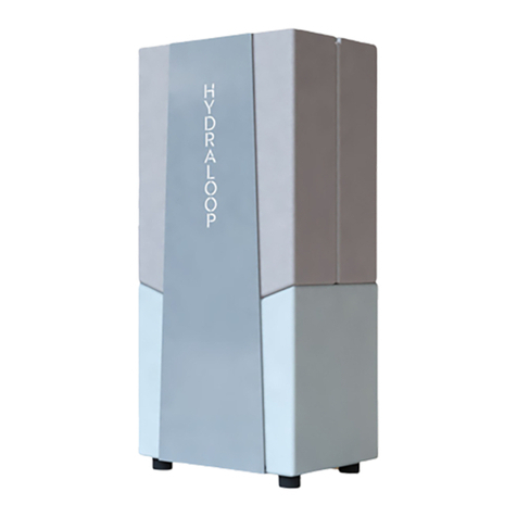
HYDRALOOP H150 User manual

Hydraloop H350, H300 & H600
Installation manual

HL-20210202 Hydraloop Installation Manual
2
Dear customer,
Thank you for purchasing this Hydraloop device.
Read this manual before using the product and keep it in a safe place for future reference. To ensure safe
and proper operation, we recommend regular maintenance of the product. Our Service and customer
service organization can help with this. We hope you will enjoy the product for many years to come.

HL-20210202 Hydraloop Installation Manual
3
Contents
1. Safety ........................................................................................................................................................ 4
1.1 General safety instructions ...................................................................................................................... 4
1.2 Recommendations ................................................................................................................................... 4
1.3 Responsibility and Liability ...................................................................................................................... 5
1.3.1 Manufacturer .............................................................................................................................. 5
1.3.2 Installer........................................................................................................................................ 5
1.3.3 User ............................................................................................................................................. 5
2. Introduction............................................................................................................................................... 6
3. Product definition...................................................................................................................................... 6
4. Design, construction & components......................................................................................................... 6
5. Off-loading and unpacking instructions.................................................................................................... 7
6. Installation................................................................................................................................................. 8
6.1 Installation considerations....................................................................................................................... 9
6.2 Installation preparation.......................................................................................................................... 10
6.3 Front plate removal................................................................................................................................ 10
6.4 Hydraloop wall mounting instructions.................................................................................................. 10
6.5 Hydraloop greywater inlet installation ................................................................................................. 11
6.6 Using a lift pump .................................................................................................................................... 11
6.7 Water in/outlets...................................................................................................................................... 12
6.8 Hydraloop wastewater outlet installation............................................................................................. 13
7. Commissioning & Initial startup of the Hydraloop unit................................................................................. 14
8. Startup time ...................................................................................................................................................... 16
9. Potable water backup & backflow prevention ............................................................................................... 16
10. Plumbing backup facility.................................................................................................................................. 17
11. System malfunction .......................................................................................................................................... 17
12. Explanation visual alarm light and audible alarm .......................................................................................... 18
13. Maintenance ..................................................................................................................................................... 18
14. Warranty ............................................................................................................................................................ 18
15. Specifications & Data Plate.............................................................................................................................. 19

HL-20210202 Hydraloop Installation Manual
4
1. Safety
1.1 General safety instructions
WARNING
!
- Read this manual before installing and/or using the Hydraloop.
- This Hydraloop creates
NON-POTABLE
water.
DO NOT
use the output water as
drinking water.
- The Hydraloop devices should only be opened or serviced by authorized
persons/installers. Risk of electric shock may occur.
- The Hydraloop should be place and installed according installation directions for save
operation.
WARNING
!
- A damaged power supply cable should always be replaced by authorized
persons/installers to avoid dangerous situations.
-
Always
disconnect the Hydraloop from the mains before servicing or maintenance.
ATTENTION
!
- After servicing the Hydraloop, the installation should always be checked for leakages.
1.2 Recommendations
ATTENTION
!
- The Hydraloop should only be placed indoor with an ambient temperature between 14-
35°C | 57-95°F.
- The Hydraloop should never be placed in direct sunlight.
- The Hydraloop should always be easily accessible for service and maintenance
ATTENTION
!
- The Hydraloop should only be moved or transported in an upright, vertical position.
ATTENTION
!
-
Never
use greywater from kitchen sinks, dishwashing machines or laundry machines as
input water to the Hydraloop. Only use water from shower, bath, or air conditioning
units.

HL-20210202 Hydraloop Installation Manual
5
1.3 Responsibility and Liability
1.3.1 Manufacturer
Hydraloop warrants the proper working of the system according to its general sales conditions.
As a manufacturer, Hydraloop is not liable in the following cases:
- Failure to follow the instructions for installation and maintenance of the Hydraloop.
- Failure to follow the instructions for use of the device.
- Inadequate or insufficient maintenance of the device
1.3.2 Installer
The installer is responsible for the installation and initial commissioning of the Hydraloop device.
- The Hydraloop device should always be installed according the local legislation and standards.
- Perform initial commissioning and necessary checks.
- Explain the installation to the user.
- Hand over all manuals to the user
1.3.3 User
To ensure optimal functioning of the Hydraloop device, please observe the following:
- Read and observe the instruction manuals of the Hydraloop device.
- Request the assistance of a qualified installer for installation, commissioning, service and
maintenance.
- Ask the installer for an explanation of the installation.

HL-20210202 Hydraloop Installation Manual
6
2. Introduction
Hydraloop Systems B.V. offers a range of patented residential greywater recycling products. Grey water from
the shower and bath is collected, cleaned and disinfected and reused for flushing the toilet, the laundry
machine and garden. Optionally, approximately 50% of the laundry machine water can be recycled through
the laundry machine recycling option. The pipes need to be prepared in the house by isolating the
drainpipes of the showers/baths from the drainpipes of other water sources (such as sinks, kitchen and
toilets). The toilet fixtures and the laundry machine have separate supply pipes for the water recycled by the
Hydraloop system (separated from potable water). Hydraloop residential water recycling products are
certified to NSF/ANSI standard 350.
3. Product definition
Hydraloop models are H150, H300, H350 and H600*
- Hydraloop water recycling unit for bathing water with one or more water outlets.
- one recycled water outlet to feed the toilet cisterns,
- a second recycled water outlet for feeding the laundry machine,
- a third recycled water outlet to use for the garden.
- in addition to recycling bathing water + 50% of the laundry water can be recycled by the Hydraloop.
* Product availability may vary by state or country.
It is not allowed to feed the Hydraloop unit with water from hand basins, dishwashers, kitchen sink or floor
drains.
4. Design, construction & components
The Hydraloop unit is a turnkey water recycling product. The Hydraloop is a pre-assembled product that
includes;
- all water tanks for treatment and storage of the treated recycled water
- a boost pump to distribute the recycled water by independent outlets to the users of the recycled
water like toilets, laundry machine and garden.
The Hydraloop unit requires:
- greywater from bath and optionally laundry machine (via the laundry water recycle option).
- one or more independent recycled water outlets depending on model and version.
- a connection to back-up water supply (potable water or rainwater).
- a connection of wastewater drain to sewer.
- a connection to electrical power.
- a connection to WiFi.
Certified to
NSF/ANSI
Standard

HL-20210202 Hydraloop Installation Manual
7
5. Off-loading and unpacking instructions
The Hydraloop unit will be transported to your location mounted and strapped onto a HL-Transport plate,
wrapped in protective foil and mounted onto a wooden pallet. When moving the Hydraloop unit it is
important to
always
keep it in an upright, vertical position. Bringing the Hydraloop unit into a horizontal
position may cause damage to its internal components and seals. It is very important to handle the
Hydraloop with care and to leave the protective foil on until it is placed at its final installation position. After
it is removed from the wooden pallet leave it strapped on the wooden transportation plate and the unit can
be moved with a 2-wheel trolley. Only when it is near its final position then remove the foil and carefully lift
the unit from the plate and place it at its final position.
Transportation of Hydraloop H300
1x Hydraloop H300 on HL-transport plate
(Transport upright!)
System individually secured to HL-transport plate with
strapping and packed in bubble- and shrink wrap.
Total dimensions (H x W x L):
190x82x40 [cm] / 74.8x32.3x15.8 [in]
Combined weight approx.:
100 [kg] / 220.5 [lb]
1x Hydraloop H300 on HL-transport plate + Europallet
(Transport upright!)
System individually secured to HL-transport plate with
strapping and packed in bubble- and shrink wrap. Placed
secured onto Europallet.
Total dimensions (H x W x L):
205x80x120 [cm] / 80.7x31.5x47.2 [in]
Combined weight approx.:
125 [kg] / 275.6 [lb]

HL-20210202 Hydraloop Installation Manual
8
6. Installation
The installation and commissioning of the Hydraloop unit can only be carried out by approved installers who
have been trained by Hydraloop Systems B.V. This chapter will provide both basic and detailed information
for the most important installation steps. The image below shows an overview of the installation principle.
See next chapters for more details to each subject. (use this image for reference).
- Use
shower & bath
water as source water and optionally laundry machine water in case a Hydraloop
laundry machine recycle option is installed.
No washbasins, kitchen sinks & dishwasher may be
connected!
- Use
shower & bath
water as source water and optionally laundry machine water in case a Hydraloop
laundry machine recycle option is installed.
No washbasins, kitchen sinks & dishwasher may be
connected!
- Connect all separated greywater pipes from shower and bathtubs via a single 2” pipe to the 1.5”
inlet on the top of the Hydraloop unit (if necessary via a lift pump).
- Hydraloop has a built-in overflow facility, no additional connection to the sewer is required
- The 50mm|2" greywater feed tube from the shower/bath
MUST
vent to open air in accordance with
local plumbing code through a vent stack to support shower water flowing without airlocks to the
Hydraloop unit and to ensure proper functioning of the Hydraloop unit.
- With the laundry machine recycle option installed, the wastewater tube from the laundry machine
needs to be fed into the inlet of the Hydraloop system via a sanitary lift pump with a built-in
overflow. The power cord of the sanitary lift pump should be connected to the Hydraloop system so
the lift pump can be controlled by the Hydraloop unit

HL-20210202 Hydraloop Installation Manual
9
Basic installation steps:
1. Check if system and installation will comply with applicable country, state or local regulations and
that the preparation of the plumbing is preventing and protected against back flow and cross
connection assuring protection of the public water supply. (Ch 6.1, 6.2 and 8)
2. Check that the greywater pipes and the distribution pipes of the recycled water have been properly
installed in accordance with the recommendations in this manual. (Ch 6.1, 6.2)
3. Place the Hydraloop unit on its planned position (Ch 6.4)
4. Connect incoming greywater to the inlet on the top, in combination with lift pump if necessary. (Ch
6.5, 6.6)
5. Connect backup water inlet connection. (Ch 6.7)
6. Connect Hydraloop recycled water outlet connections (Ch 6.7)
7. Connect Hydraloop wastewater outlet to sewer (Ch 6.7 and 6.8)
8. Plug 100-240V power cord into wall socket
9. Run the commissioning test using the Hydraloop App (Ch 7)
6.1 Installation considerations
Note; The plumbing connections for greywater and backup water inlets and recycled water outlets and
Hydraloop wastewater outlet can be installed concealed in the floor, under the floor or mounted on the floor
& wall behind the Hydraloop unit. An example of concealed connections can be seen in the left images
below. On-floor & wall connections can be seen in the right images.

HL-20210202 Hydraloop Installation Manual
10
6.2 Installation preparation
We strongly recommend - in case of new build -
not
to place, connect and commission the Hydraloop unit
during the building process but only
after
the house is fully ready and all works are finished. At all times
avoid that building dirt, chemicals or sand can enter into the Hydraloop unit as it will cause damage.
A temporary bridge connection can be installed
so that backup water (freshwater or rainwater)
can serve the toilets and laundry machine and
greywater from showers flows direct to the
sewer until the Hydraloop unit is installed. More
information regarding installation preparation
can be found in our
FACT SHEET "Have your
building Recycle Ready"
.
6.3 Front plate removal
Remove the stainless-steel front plate, using a lever, on the lower side of the front plate to carefully lift the
stainless plate up. The plate is holding its position due to its shape so once it comes upwards it will be free
to remove. Perform with care.
6.4 Hydraloop wall mounting instructions
Hook the mounting hole of the Hydraloop top plate onto the screw thumb, which you should plug into the
wall, so the Hydraloop is fixed to the wall and protected against falling over.

HL-20210202 Hydraloop Installation Manual
11
6.5 Hydraloop greywater inlet installation
Place the Hydraloop supply pipe and incoming water sensor as following:
1. First place the blue sealing ring in the top lid in feed channel.
2. Install the in-feed tube system into the sealing ring with a minimal
amount of grease (Vaseline) applied on the Y-tube end.
3. Connect the air release tube in the push-in fitting of the branch of
the Y-tube.
4. Connect the solid blue pressure sensor near the 45°bend.
5. Connect the transparent pressure sensor near the 90° bend.
6.6 Using a lift pump
If the Hydraloop unit is on the same or higher floor as the shower/bath or laundry machine an appropriate lift
pump has to be installed to pump the greywater from the source up into the Hydraloop system.
If a Hydraloop unit is equipped with the laundry machine water recycle option, the ideal place for installation
would be close to the laundry machine, so that the laundry machine lift pump can be placed next or close to
the laundry machine itself. If the laundry machine is placed on the same floor as the Hydraloop but in
another room, the laundry machine lift pump can be installed close to the laundry machine itself and the
greywater is lifted up, and from there flows by gravity to the Hydraloop unit water inlet. The laundry machine
lift pump is controlled by the Hydraloop unit. The laundry machine lift pump power cord should be
connected to the Hydraloop. For more information check the installation manual of the applied lift pump.

HL-20210202 Hydraloop Installation Manual
12
6.7 Water in/outlets
The Hydraloop can feed multiple toilets. A second Hydraloop outflow valve feeds the laundry machine. The
Hydraloop unit can have optionally a third valve-controlled water output which can supply recycled water to
the garden or pool. Note that this outlet will not be permanently pressurized, unlike the other water outlets.
This outlet only supplies when a surplus of recycled water is available.
Connection specifications Hydraloop H350, H300, H600
Input connection
Size
(imperial)
Size
(metric)
Thread
type
Additional information
-
Greywater supply
1.5"
40 mm.
-
Into feed channel
1.
Backup water supply
1/2"
male
Min. Flow 4.5 Gallon - 20 liters p/m
Output connection
Size
(imperial)
Size
(metric)
Thread
type
Additional information
2.
Garden/pool supply
1/2"
Connect to flexible hose
3.
Toilet supply
1/2"
male
Connect to flexible hose
4.
Laundry machine supply
(optional)
1/2"
male
Connect to flexible hose
5.
Drainpipe (wastewater)
1.5"
40 mm.
male
Into rubber sleeve (chapter 7)
Label or color code the water pipes to designate that these water pipes are running recycled water. Check
local plumbing code’s if applicable. Draw-off points for non-potable water shall be identified with the words
"Non-potable water" or by a prohibition sign as shown below.

HL-20210202 Hydraloop Installation Manual
13
6.8 Hydraloop wastewater outlet installation
The 40mm|1.5" wastewater drainpipe below the Hydraloop unit has to be connected to the sewer with PVC
eccentric adapter ring or *rubber reducing sleeve trough the floor (first image) or backwards to the wall
(second image)
Hydraloop drainpipe connected to sewage by using reducing sleeve
A backwards connection to the sewage system
*(Rubber reducing sleeve)

HL-20210202 Hydraloop Installation Manual
14
7. Commissioning & Initial startup of the Hydraloop unit
The commissioning should be performed by an accredited Hydraloop Partner that is trained to commission
the Hydraloop unit.
Commissioning steps:
1. Open external back up water source (tap or rainwater). Be sure the water pipe is rinsed before
connecting to the Hydraloop unit so there is no dirt entering the float valve and Hydraloop unit,
because this could damage the float valve, electric valves and the water pump.
- The small water tank on the lower left side should fill with water and the float valve should close
when the maximum water level in the tank is reached.
2. Switch Hydraloop power switch on
- This start up procedure takes about 2 minutes.
- After this, please flush each toilet after each other in the building once, to push air out of the
pipes.
- The Hydraloop unit will now only supply backup water to the house because at this stage the
Hydraloop unit is not yet activated for recycling. The LED light on the front plate will be green.
You can now check all connections to and from the Hydraloop unit for leaks.
3. WiFi setup: After the Hydraloop unit is switched on, it will automatically create a WiFi network
showing a number (looks like 00:AB:00:AB:11)
- elect this Hydraloop WiFi network, that shows the long number, on your smart phone, tablet or
computer (device) and enter the password: PASSWORD
- Check if your device is connected to the Hydraloop WiFi network (with the long number).
- Open an internet browser on your device and enter the
URL 192.168.4.1. A page will open.
- Enter the existing WiFi network of the house/building
that you want the Hydraloop unit to connect with, and
enter the password belonging to this WiFi network on the
page that is displayed and press ‘Submit’. The Hydraloop
unit will now connect with this local WiFi network. Note:
Spaces, commas, capitals etc. all should be entered
correctly.
Note: If the WiFi network does not have a password leave this
field blank.
4. Enter/scan Hydraloop ID with Hydraloop App:
- Download and open the Hydraloop app on a smartphone (IOS or Android). Go to ‘settings,
installation, enter/scan Hydraloop ID’.
- Enter the serial number of the Hydraloop unit that is printed on the Hydraloop Data Plate that is
attached on the right hand top of the Hydraloop unit,
- or press ‘scan barcode’ and scan the bar code that is visible on the same Hydraloop Data Plate
that is attached on the right hand top of the Hydraloop unit.
- After the information is entered correctly the central server at Hydraloop Systems B.V. will
connect to this specific Hydraloop unit and will perform a brief system check.
5. Installers Initial Setup: For the initial setup the installer needs to press ‘Setup Hydraloop’ and enter
the ‘installers code’. This will give access to the ‘setup’ section of the App.
- (if you do not have the installers code please contact Hydraloop Systems B.V.)

HL-20210202 Hydraloop Installation Manual
15
After this, three options are accessible:
1.
System restart
: Pushing this button restarts the
Hydraloop system.
2.
Empty tanks
: Pushing this button opens the purge
valves of the Hydraloop system. This might be
necessary for servicing.
It is also possible to empty the water tanks without WiFi
connection/App:
- unplug the power plug from the wall socket,
- wait until the audible alarm (2 beeps) sound,
- immediately plug in again, if inserted back in time
1 confirmation* beep will sound,
- immediately unplug the power plug again,
- after 2 beeps immediately plug it in again.
* If the 1 confirmation beep did not sound, you have to insert
quicker after the 2 beeps. To repeat the procedure: wait 1
minute and repeat procedure.
3. Test routine: This option starts the Hydraloop test
routine. The test routine performs all actions the
Hydraloop normally performs for treatment in about 15
minutes. This test should always be performed at
installation and after replacement of parts. It is
necessary to do a test routine to check for possible
damage caused by transportation of the unit:
a. Open the Hydraloop front plate by lifting it from
the floor up and then you can move it upwards and
set it aside, so all tanks and internal parts are
visible,
b. Press ‘test routine’ and open one of the showers in
the house and wait until shower greywater enters
the Hydraloop unit. Let it run for about 12 minutes
and then close the shower. The test routine takes
about 15 minutes in total. After this test routine the
system is ready for usage. If an issue occurs the
App will inform you about the issue. If you have
questions, please contact us.
Note: Check the Hydraloop unit for water leaks during the test routine.
If you need assistance call your Hydraloop dealer or contact Hydraloop technical support via email
or phone on number:
+31 88 100 3500 (EU) | +1 414 89 500 21 (USA)

HL-20210202 Hydraloop Installation Manual
16
8. Startup time
The Hydraloop unit needs 21 days to develop the biological treatment process and to become fully
operational. The greywater treatment will start from the very first day, however this recycled water will be
purged into the sewer and backup water will be supplied instead of recycled water. After this start up period
of 21 days, the Hydraloop unit will automatically switch over to offer recycled water to the toilets, laundry
machine and/or garden.
9. Potable water backup & backflow prevention
In the event there is not enough recycled water available, the system will automatically switch to back-up
water (potable or rainwater). As soon as new recycled water is available the Hydraloop unit will automatically
switch to supply recycled water. The Hydraloop unit is connected to its backup water supply via an air gap to
protect the tap water against back flow or cross contamination. Additionally, a non-return valve is mounted
on the point of incoming backup water.

HL-20210202 Hydraloop Installation Manual
17
10. Plumbing backup facility
In case of maintenance or power failure it might be possible that supply of treated recycled water or back-up
water is temporarily not available. To overcome this a bypass facility can be installed.
The bypass setup must comply with the applicable regulations of the country, state or municipality.
A bypass facility as show in the picture below using a flexible hose could be made to ensure availability of
water.
11. System malfunction
The Hydraloop unit is a very reliable system and all critical components are monitored continuously by the
unit itself and by the Hydraloop server through the WiFi internet connection. In the unlikely event a
component fails - for example the UV lamp - the Hydraloop unit will automatically switch to its backup water
and everything in-house will function as usual, but no recycled water will be distributed as a precaution. The
visual alarm light on the Hydraloop front plate will blink red 4 times per minute indicating an abnormal
situation, a warning message is sent via the WiFi connection to the Hydraloop monitoring server and to the
customers Hydraloop App and an audible beep as well will sound 4 times per minute. (see more about
alarms on page 23, article 14)
Warning: Hydraloop is designed for ‘normal usage’ and is not designed to receive solid materials like stones,
chemicals, paint residues, hair dye, bleach and disinfectants or any other matter that is unusual for
shower/bath and laundry machine water. In the event these substances are entered into the Hydraloop unit,
the system itself can be damaged and the water treatment can be disturbed.
Note: Hydraloop Systems BV is not liable for any damage if the above or any other abnormal substances are
entered into the Hydraloop unit and the unit and/or the laundry machine/laundry is therefore damaged.

HL-20210202 Hydraloop Installation Manual
18
12. Explanation visual alarm light and audible alarm
If one of the below mentioned alarms are activated, the Hydraloop unit will stop offering recycled water and
will offer backup water unless in case of Water distribution pump failure.
High water alarm:
Audible alarm 2 beeps every minute, visual alarm 2 light pulses every minute
Air pump alarm:
Audible alarm 3 beeps every minute, visual alarm 3 light pulses every minute
UV-C disinfection lamp alarm:
Audible alarm 4 beeps every minute, visual alarm 4 light pulses every minute
Water circulation failure:
Audible alarm 5 beeps every minute, visual alarm 5 light pulses every minute
Water distribution pump failure:
Audible alarm 6 beeps every minute, visual alarm 6 light pulses every minute
In case of a water distribution pump failure, it can happen that water distribution to the users is blocked or
limited
If you need assistance call your Hydraloop dealer or contact Hydraloop technical support via email
or phone on number:
+31 88 100 3500 (EU) | +1 414 89 500 21 (USA)
13. Maintenance
We recommend a check performed by a Hydraloop accredited installer once every two years.
This check contains the following elements:
- Descale the Hydraloop unit with a citric acid solution to descale the integrated water tanks.
- Remove, clean and descale the air diffuser.
- Replace the rubber membranes of the air pump every three years (according to the manual of the air
pump supplier).
- Replace the UV light bulb every two years by unscrewing the lid on the UV-C lamp housing.
- Effluent samples can be collected using the water valve that is connected to the laundry machine.
In regions with very high levels of water hardness more frequent descaling of the water tanks may be necessary.
Please check water hardness during installation.
14. Warranty
Hydraloop Systems B.V. provides a 5-year warranty starting on the delivery date on all non-wearing parts, and
a 1-year warranty on all other parts.

HL-20210202 Hydraloop Installation Manual
19
15. Specifications & Data Plate
Dimensions (WxDxH):
80cm|31.5" x 34cm|13.5" x 185cm|75" *
*please note that with the incoming water pipes 210cm|83" of height is required.
Material specification:
The water tanks are made of Medium Density Polyethylene.
Backup water (potable or rain water) connections:
Flow minimal 20 lit.|4.5 gal. per minute, pressure minimal 2 bar|29 Psi.
Power supply:
100/240V, 20W (24V internal)
Expected power consumption:
±200 kWh/year
Average recycled water quality:
Hydraloop Residential water recycling products are certified to NSF/ANSI standard 350
CBDO5 (mg/L) < 10
TSS (mg/L) < 10
Turbidity (NTU) < 5
E. coli (MPN/100mL) < 14
PH (SU) 6.0 - 9.0
Noise level:
+ 44 dB
Data Plate / Service Label:
The Hydraloop unit has a permanent data plate attached on the top of the unit that should look like the
example below.
Certified to
NSF/ANSI
Standard 350

HL-20210202 Hydraloop Installation Manual
20
This document and its contents are the sole property of Hydraloop Systems B.V. and must not be copied to a
third party either in part or whole without prior written consent of Hydraloop Systems B.V.
Hydraloop reserves the right to change the specifications stated in this document.
Hydraloop products are protected by patents and patents pending. The Hydraloop brand name is a registered
trademark.
Hydraloop Inc.
Global Water Center,
247 W. Freshwater Way, Suite 210
Milwaukee, WI 53202
United States of America
+1 414 89 500 21
Hydraloop Systems B.V.
Wetsus Building, Water Campus
Oostergoweg 9
8911 MA Leeuwarden
Netherlands
+31 88 100 3500
E-mail:
info@hydraloop.com
Website:
www.hydraloop.com
This manual suits for next models
3
Table of contents
Other HYDRALOOP Water Filtration System manuals
Popular Water Filtration System manuals by other brands

Water Right
Water Right UltroWater Installation, operation & service manual

EcoQuest
EcoQuest Living Water IIs CT owner's manual

Zip
Zip ChillTap CT1/140 Installation and operating instructions

Veolia
Veolia ELGA CENTRA-MDS-US Operator's manual

Forbes
Forbes FLO user manual

Hellenbrand
Hellenbrand 7 owner's manual