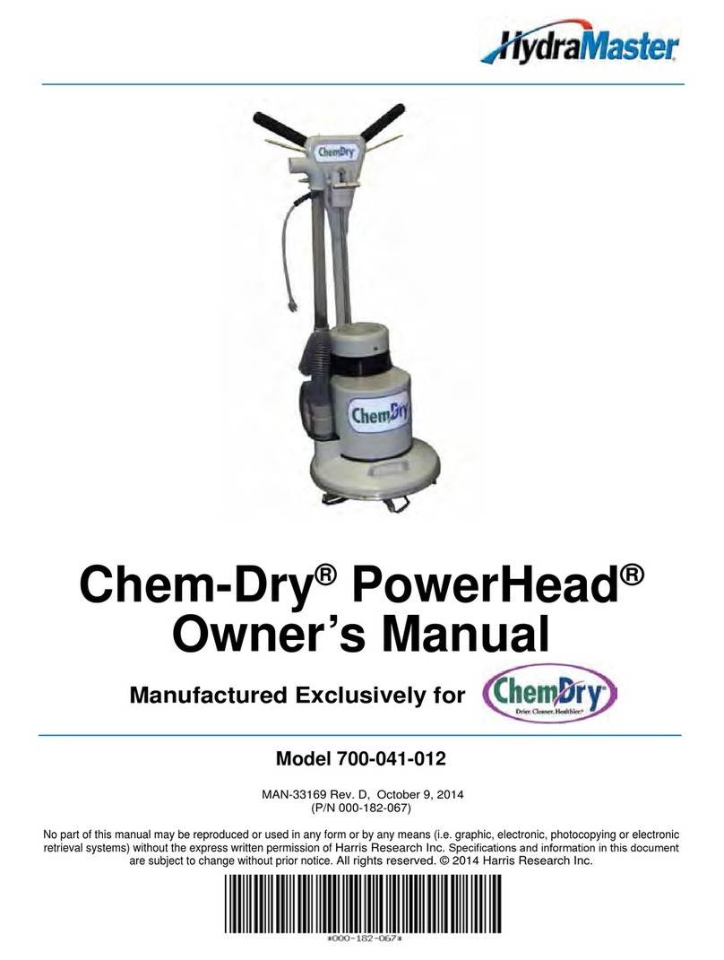
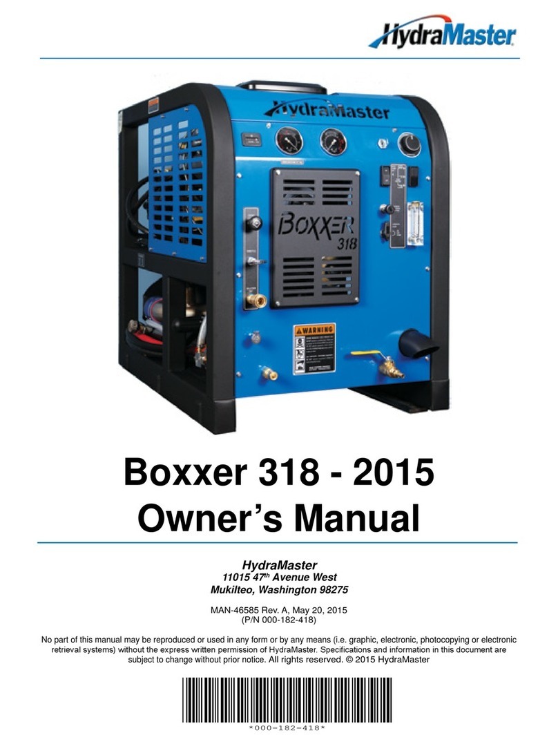
HydraMaster ChemDry CTS 4600 CDS User manual

CTS 4600/4800 CDS
Hot Carbonating Truckmount
System Owner’s Manual
Manufactured Exclusively for
HydraMaster North America, Inc.
11015 47th Avenue West, Mukilteo, Washington 98275
MAN-33193 Rev. 1, November 5, 2010
(000-182-700)
No part of this manual may be reproduced or used in any form or by any means (i.e. graphic, electronic, photocopying
or electronic retrieval systems) without the express written permission of HydraMaster North America, Inc.
All rights reserved. © 2010 HydraMaster North America, Inc.


i - CTS CDS Owner’s Manual
CTS 4600/4800 CDS
Table of Contents
GENERAL INFORMATION........................................................................... SECTION 1
System Concept......................................................................................1-2
Contact Information................................................................................. 1-3
Warnings, Cautions and Notices.............................................................1-4
Responsibilities....................................................................................... 1-8
Machine Specications ........................................................................... 1-9
Spare Parts Lists..................................................................................... 1-11
Waste Water Disposal Advisory..............................................................1-12
INSTALLATION INFORMATION...................................................................SECTION 2
Vehicle Preparation.................................................................................2-1
OPERATING INSTRUCTIONS.....................................................................SECTION 3
Compressor System Background ........................................................... 3-2
Solution valve Background......................................................................3-3
Before Operating the CTS CDS.............................................................. 3-4
Start Up Procedure ................................................................................. 3-5
Carpet or Upholstery Cleaning................................................................ 3-5
Flood Extraction and Restoration Work .................................................. 3-7
Shut Down Procedure............................................................................. 3-8
MACHINE MAINTENANCE..........................................................................SECTION 4
General Maintenance (Performed Monthly)............................................ 4-1
Van Engine..............................................................................................4-1
Blower..................................................................................................... 4-2
Recovery Tank ........................................................................................4-3
Compressor System................................................................................4-3
Solution System...................................................................................... 4-4
Freeze Guard Information....................................................................... 4-5
CHEMICAL SYSTEM...................................................................................SECTION 5
ELECTRICAL SYSTEM................................................................................SECTION 6
SYSTEMS TROUBLESHOOTING...............................................................SECTION 7
Heating System.......................................................................................7-2
Miscellaneous .........................................................................................7-3
Electrical System.....................................................................................7-4
Vacuum Blower System..........................................................................7-5

CTS CDS Owner’s Manual - ii
CTS 4600/4800 CDS
MACHINE ASSEMBLIES AND PARTS LIST................................................ SECTION 8
Machine Assembly Parts List - Chevy - 4.8 ............................................ 8-5
Machine Assembly Parts List - Ford - 4.8...............................................8-9
Machine Assembly Parts List - Chevy - 4.6 ............................................ 8-13
Machine Assembly Parts List - Ford - 4.6 ..............................................8-17
Recovery Tank Assembly Parts List - Chevy .......................................... 8-20
Recovery Tank Assembly Parts List - Ford ............................................8-23
Recovery Tank Cover Assembly Parts List ............................................8-24
Frame Assembly - 4.8 - Parts List ..........................................................8-27
Frame Assembly - 4.6 - Parts List ..........................................................8-30
Blower Assembly - 4.8 Parts List ............................................................8-32
Blower Assembly - 4.6 - Parts List .........................................................8-34
Compressor Assembly Parts List ...........................................................8-36
Dash Box Assembly Parts List ...............................................................8-38
Dash Panel Assembly Parts List ............................................................8-39
Instrument Panel Assembly Parts List - Chevy ......................................8-42
Instrument Panel Assembly Parts List - Ford..........................................8-45
Solution Manifold Assembly Parts List ...................................................8-46
Chemical Tray Assembly Parts List ........................................................8-47
Coolant Heat Exchanger Assembly Parts List - Chevy...........................8-49
Coolant Heat Exchanger Assembly Parts List - Ford..............................8-51
Heat Exchanger Assembly Parts List......................................................8-52
Dura-Flow Automatic Pump Out (APO)Assembly Parts List ................. 8-54
Vacuum Relief Valve Assembly Parts List ..............................................8-55
Pass ThruAssembly Parts List .............................................................. 8-56
15 Gallon Solution Tank Assembly Parts List ......................................... 8-58
GM Cowling Assembly, 2003 – 2009 Parts List (P/N 601-020-008)........ 8-59
2009 Ford Cowling Assembly Parts List (P/N 601-020-001)...................8-59
CDS Parts Kit List (P/N 000-078-069).....................................................8-59
2008 - 2010 GM Throttle Kit Parts List (P/N 000-078-430)..................... 8-59
CDS Belts Parts List................................................................................8-59
2006 - 2010 Ford Throttle Kit Parts List (P/N 000-078-405) ................... 8-60
Hose Routings - Chevy .......................................................................... 8-64
Hose Routings - Ford ............................................................................. 8-68

iii - CTS CDS Owner’s Manual
CTS 4600/4800 CDS
HOW TO ORDER PARTS............................................................................SECTION 9
Warranty Parts Orders............................................................................ 9-1
Parts Orders............................................................................................9-1
Emergencies........................................................................................... 9-1
WARRANTY INFORMATION....................................................................... SECTION 10
Blower ....................................................................................................10-1
Vacuum Tank ..........................................................................................10-1
Solution System...................................................................................... 10-1
Vacuum and Solution Hoses ..................................................................10-1
Warranty Procedure................................................................................10-1

CTS CDS Owner’s Manual - iv
CTS 4600/4800 CDS
List of Figures
Figure 3-1. Location of Compressor Valve.............................................................3-2
Figure 3-2. Location of Cleaning Switch ................................................................3-3
Figure 3-3. Location of Solution Valve ...................................................................3-3
Figure 3-4. Location of Solution Out Connection...................................................3-4
Figure 3-5. Location of Run Switch........................................................................3-5
Figure 3-6. Position Compressor Valve to “PRESSURE RELIEF”.........................3-5
Figure 3-7. Location of Coolant Flow Valve ...........................................................3-7
Figure 3-8. Set Cleaning Mode Switch to “EXTRACTION MODE”........................3-7
Figure 3-9. Location of Blower Lube Port...............................................................3-8
Figure 4-1. Location of Blower Oil Relief Caps and Sight Glasses........................4-2
Figure 4-2. Location of Orice Assembly on Side of Solution Tank........................4-4
Figure 5-1. Annotated Chemical andAir Flow Diagram.........................................5-2
Figure 5-2. Solution and Exhaust Flow Diagram....................................................5-3
Figure 6-1. CTS CDS Wiring Diagram - View 1 of 2 .............................................6-2
Figure 6-2. CTS CDS Wiring Diagram View 2 of 2 ...............................................6-3
Figure 6-3. CTS CDS Electrical Schematic............................................................6-4
Figure 8-1. Machine Assembly - Chevy - 4.8 View 1 of 3 ......................................8-2
Figure 8-2. Machine Assembly - Chevy - 4.8 View 2 of 3 ......................................8-3
Figure 8-3. Machine Assembly - Chevy - 4.8 View 3 of 3 ......................................8-4
Figure 8-4. Machine Assembly - Ford - 4.8 View 1 of 3.........................................8-6
Figure 8-5. Machine Assembly - Ford - 4.8 View 2 of 3.........................................8-7
Figure 8-6. Machine Assembly - Ford - 4.8 View 3 of 3.........................................8-8
Figure 8-7. Machine Assembly - Chevy - 4.6 View 1 of 3 ...................................8-10
Figure 8-8. Machine Assembly - Chevy - 4.6 View 2 of 3 ...................................8-11
Figure 8-9. Machine Assembly - Chevy - 4.6 View 3 of 3 ...................................8-12
Figure 8-10. Machine Assembly - Ford - 4.6 View 1 of 3.....................................8-14
Figure 8-11. Machine Assembly - Ford - 4.6 View 2 of 3 .....................................8-15
Figure 8-12. Machine Assembly - Ford - 4.6 View 3 of 3.....................................8-16
Figure 8-13. Recovery Tank Assembly - Chevy View 1 of 2 ................................8-18
Figure 8-14. Recovery Tank Assembly - Chevy View 2 of 2 ................................8-19
Figure 8-15. Recovery Tank Assembly - Ford View 1 of 2...................................8-21
Figure 8-16. Recovery Tank Assembly - Ford View 2 of 2...................................8-22
Figure 8-17. Recovery Tank Cover Assembly......................................................8-24
Figure 8-18. Frame Assembly - 4.8 - View 1 of 2.................................................8-25
Figure 8-19. Frame Assembly 4.8 - View 2 of 2...................................................8-26
v - CTS CDS Owner’s Manual
CTS 4600/4800 CDS
Figure 8-20. Frame Assembly 4.6 - View 1 of 2...................................................8-28
Figure 8-21. Frame Assembly - 4.6 - View 2 of 2.................................................8-29
Figure 8-22. Blower Assembly - 4.8.....................................................................8-31
Figure 8-23. Blower Assembly - 4.6.....................................................................8-33
Figure 8-24. Compressor Assembly ....................................................................8-35
Figure 8-25. Dash Box Assembly ........................................................................8-37
Figure 8-26. Dash Panel Assembly .....................................................................8-39
Figure 8-27. Instrument Panel Assembly - Chevy - View 1 of 2...........................8-40
Figure 8-28. Instrument Panel Assembly - Chevy - View 2 of 2...........................8-41
Figure 8-29. Instrument Panel Assembly - Ford - View 1 of 2..............................8-43
Figure 8-30. Instrument Panel Assembly - Ford - View 2 of 2..............................8-44
Figure 8-31. Solution Manifold Assembly ............................................................8-46
Figure 8-32. Chemical Tray Assembly ................................................................8-47
Figure 8-33. Coolant Heat Exchanger Assembly - Chevy....................................8-48
Figure 8-34. Coolant Heat Exchanger Assembly - Ford.......................................8-50
Figure 8-35. Heat Exchanger Assembly...............................................................8-52
Figure 8-36. Dura-Flow Automatic Pump Out (APO)Assembly...........................8-53
Figure 8-37. Vacuum Relief Valve Assembly .......................................................8-55
Figure 8-38. Pass ThruAssembly .......................................................................8-56
Figure 8-39. 15 Gallon Solution Tank Assembly .................................................8-57
Figure 8-40. Hose Routings - Chevy - View 1 of 3...............................................8-61
Figure 8-41. Hose Routings - Chevy - View 2 of 3...............................................8-62
Figure 8-42. Hose Routings - Chevy - View 3 of 3...............................................8-63
Figure 8-43. Hose Routings - Ford - View 1 of 3..................................................8-65
Figure 8-44. Hose Routings - Ford - View 2 of 3..................................................8-66
Figure 8-45. Hose Routings - Ford - View 3 of 3..................................................8-67

CTS CDS Owner’s Manual - vi
CTS 4600/4800 CDS

1-1: General Information
CTS 4600/4800 CDS
1 - General Information
The CTS 4600/4800 Clutch Drive System (CDS) is a highly engineered carpet cleaning
and ood extraction machine, designed and manufactured for Chem Dry for use in all
Ford and GMC vans (2006 model year and later).
The CTS CDS units, which utilize the most current technology available in solution and
recovery systems, are available in four congurations:
CTS 4600 CDS featuring a 45 Tuthill vacuum blower for a Ford or Chevy van or1. CTS 4800 CDS featuring a 47 Tuthill vacuum blower for a Ford or Chevy van2.
In addition to the Tuthill blower, other major components of the basic machine include a
Thomas air compressor, a drive system, a stainless steel coolant heat exchanger and a
100 gallon recovery tank.

General Information: 1-2
CTS 4600/4800 CDS
Other features of the CTS CDS include:
Full instrumentation with control console• Stainless steel Salsa heat exchanger• One 15 gallon solution tank• Equipment cowling with armrests• Freeze guard system• Solution hose• Two vacuum hoses• Optional Dura-Flow Automatic Pump-Out (APO)•
Thismanualcontainsinstallationandoperationinstructionsaswellasinformationrequired
for proper maintenance, adjustment and repair of the CTS 4600/4800 CDS systems.
Component troubleshooting guides have also been included for your convenience.
PleasereadthisOwner’sManualtofamiliarizeyourselfwiththeoperationoftheTruckmount
Systems, paying special attention to all Warnings and Cautions.
SYSTEM CONCEPT
The CTS 4600/4800 CDS cleaning system works this way:
Compressed air pushes the cleaning solution out of the tanks.
1.
Solution then ows through the heat exchange system. 2. If the cleaning tool is in use and the solution is at the desired temperature, the3.
solution will ow through the solution outlet.
The heated cleaning solution is applied to the
4. cleaning surface.
Used solution from the cleaning surface is sent to the recovery tank.5.
See Section 5 of this Owner’s Manual for a detailed explanation and ow diagrams.

1-3: General Information
CTS 4600/4800 CDS
CONTACT INFORMATION
If you have any questions regarding the operation, maintenance or repair of this machine,
please contact your local distributor.
If your question cannot be resolved by your distributor or by the information within this
manual, you may contact HydraMaster Customer Service direct using the following phone
numbers.
Hours Telephone Numbers E-mail Addresses
Monday-Friday (425) 775-7275 Service Tech Support:
techsupport@hydramaster.com
7:00 a.m. to 5:00 p.m. (425) 775-7276 Parts Parts Support:
parts@hydramaster.com
Pacic Standard Time (800) 426-4225 Parts /
Service FAX
When calling your distributor, be sure to reference the serial number and date of
purchase.
FOR YOUR REFERENCE:
Serial No.____________________________________________________
Date of Purchase:_____________________________________________
Purchased From (Distributor): __________________________________

General Information: 1-4
CTS 4600/4800 CDS
WARNINGS, CAUTIONS AND NOTICES
HydraMaster uses this WARNING symbol throughout the manual to warn of
possible injury or death.
This CAUTION symbol is used to warn of possible equipment damage.
This NOTICE symbol indicates that federal or state regulatory laws may apply,
and also emphasizes supplemental information.

1-5: General Information
CTS 4600/4800 CDS
Warnings and Cautions specic to the CTS 4600/4800 CDS include:
HOT SURFACES: During the operation of this equipment, many surfaces on the
machine will become very hot. When near the van for any reason care must be
taken not to touch any hot surface, such as heater, engine, exhaust, etc.
HEARING PROTECTION: The Occupational Safety and Health Administration
(OSHA) recommends the use of hearing protection when a technician is exposed
to an average of 85 decibels (this is an average of exposure over an 8 hour
period). This equipment can produce 85 decibels to a distance of 10 feet. Please
check with your local state agencies to see if OSHA standards apply to your
application.
NO SMOKING: It is unsafe to smoke in or around the vehicle.
CARBON MONOXIDE: This unit generates toxic fumes. Position the vehicle so
that the fumes will be directed away from the job site. Do not park where exhaust
fumes can enter a building through open doors, windows, air conditioning units
or kitchen fans.
TOXIC FUMES: Do not occupy the vehicle when the cleaning equipment is
operating. Toxic fumes may accumulate inside a stationary vehicle and cause
bodily injury.
ENGINE EXHAUST: The engine exhaust from this product contains chemicals
knowntotheStateofCaliforniatocausecancer,birthdefectsorotherreproductive
harm.
VACUUM HOSE: Do not leave the vacuum hose unattended during operation.
This could cause bodily injury.

General Information: 1-6
CTS 4600/4800 CDS
MOVING PARTS: Never touch any part of the machine that is in motion. Severe
bodily injury may result.
TRANSPORTATION OF FUEL CONTAINERS: Transportation in a vehicle of any
vented fuel container that presently has or has ever contained a ammable liquid is
strictly forbidden by Harris Research Inc. and by federal and state regulations.
EXHAUST SYSTEM: Do not allow ammable material (i.e. oil, fuel, plastic, or
wood products) to come in contact with the exhaust system. Doing so may cause
bodily injury.
VACUUMSYSTEM:Whenmachineisbeingrunfortestpurposesandthevacuum
inlet on top of the machine is open, caution should be used.
To protect the vacuum blower from over loading and damaging itself, there is a
vacuum relief system installed on the vacuum tank. When the vacuum tank inlet
is completely sealed off, a maximum of 12” Hg will be attained.
VACUUM TANK: Foam passing through the blower could lead to equipment
malfunction. Therefore, it is important to keep the vacuum tank foam free.
The use of some chemicals through your mobile carpet cleaning plant can
seriously damage the internal plumbing and heat exchangers. These harmful
chemicals include concentrated acid, solvents (including d-Limonene), and some
paint, oil and grease removers with a high concentration of solvents.
THROUGH-FLOOR DRILLING: Be cautious when drilling holes through the van
oor. Many vans have critical components mounted directly below the van oor
that could be damaged by a misplaced drill bit.)

1-7: General Information
CTS 4600/4800 CDS
LEVEL OPERATION: During operation, the van must be parked on level ground
not to exceed + or - 10 degrees. Failure to ensure proper leveling may prevent
proper internal lubrication of engine, vacuum and/or high pressure components.
FREEZEPROTECTION:Thereisoftenlittlewarningbeforeacoldspell.Therefore,
not protecting this equipment from freezing will result in costly down-time. Placing
an electric heater in the truck or parking the truck indoors will help to ensure
against freezing, but should not be the primary method of freeze protection. (See
page 4-5 of this Owner’s Manual for more information.)

General Information: 1-8
CTS 4600/4800 CDS
RESPONSIBILITIES
Prior to the arrival of the unit, the van that it will be installed in should be delivered to the
installer.
Purchaser’s Responsibility
If you are the purchaser, it is the your responsibility to read this Owner’s Manual and to
familiarize yourself with the information contained herein, paying special attention to all
Warnings and Cautions.
Equipment Installer’s Responsibility
Acceptance of Shipment
If the unit shows any outward signs of damage, do not sign the delivery receipt until1. you have closely inspected the unit and noted any damage on the delivery receipt.
The equipment installer is responsible for the correct installation of the unit in your2. vehicle and thoroughly training you in its operation, maintenance and precautions.
Correct installation includes:
Placing the unit and recovery tank in your vehicle and securing them with bolts and
• tie down cleats.
Checking the vacuum blower and engine oil levels prior to starting the unit.• Starting the unit to see that all other systems function normally.• Checking all hoses, wands and accessories for correct operation.•
Training shall include:
A thorough review of the operation manual with the purchaser.• A thorough review of the unit warranty and warranty procedures• Instruction and familiarization in:• How to correctly start up and shut down the unit1. How to correctly clean with the unit2. Where and how often to check and change component oil levels3. How the unit’s systems work4. How to troubleshoot the unit5. How to do basic repairs6. Safety precautions and their importance7. How to avoid freezing damage8.

1-9: General Information
CTS 4600/4800 CDS
MACHINE SPECIFICATIONS
Frame 13” W x 68” L x 38” H
Weight 575 lbs.
Construction Recovery Tank Marine Aluminum with Baked-
on Epoxy Finish
Chassis Painted Steel
Cowling Fiberglass
Power Transfer Electric Clutch-driven Shaft
Vacuum Blower 4600 - 45 Tuthill/M-D Tri-Lobe
4800 - 47 Tuthill/M-D Tri-Lobe
Air Pump Thomas Compressor
Heating System Coolant Heat Exchanger
Salsa Heat Package
Instruments Main Panel Electronic Tachometer,
0-3,000 rpm*
Vacuum Gauge, 0 - 30” Hg
Hour Meter, Machine Run-
Time
Keyless Ignition
Extraction/Cleaning Mode
Switch
Engine Coolant Temperature
Gauge, 0 - 250° F
Pump Out Operating Lamp
Vacuum Tank Full Lamp
Recovery Tank Drain Valve
Automatic Pump Out Switch
(if APO is included in
conguration)
Side Panel 0 - 150 psi Air Pressure Gauge
Blower Lubrication Port
High Pressure Solution Outlet,
Quick-Disconnect

General Information: 1-10
CTS 4600/4800 CDS
Recovery Tank 100 gallon
High Pressure Hose 3/16” High Temperature, Lined,
Vinyl Covered
Hose rated to 200 psi.
Standard
Equipment Machine Power Console
Component Power Pack
Full Instrumentation
Stainless Steel Solution
Heating Package
Fiberglass Equipment Cowling
Recovery Tank
Control Console
Heat Exchanger System
Freeze Guard System
Wheel Chock Set
150 ft, 3/16” Solution Hose
150 ft, 2” Vacuum Hose
10 ft. 1 ½” Vacuum Hose
10 ft, 1 ½” Recovery Drain Line
Solution Tank Holder
One 15 gallon Solution Tank
Owner’s Manual (on CD)
Owner’s Guide (paper copy)
Oversize Air Handling Package
475 cfm High-Output Vacuum
System (4800)
Van Installation Kit
*The CTS CDS 4600/4800 CDS tachometer, with the magnetic pick up located on the
power pack has been calibrated to represent the engine speed of the vehicle.

1-11: General Information
CTS 4600/4800 CDS
SPARE PARTS LISTS
Part No. Description Qty
000-052-166 Connector, 2” 1
000-052-168 Connector, 2” Plastic 5
000-052-226 Insert,1 1/2” NPT 1
000-052-227 Reducer Cuff 2” 2
000-087-006 Lubricant, Blower 1
000-169-233 Compressor Relief (Pop Off) Valve 1

General Information: 1-12
CTS 4600/4800 CDS
WASTE WATER DISPOSAL ADVISORY
There are laws in most communities prohibiting the dumping of recovered “gray” water
from carpet cleaning in any place but a sanitary treatment system.
The cleaning solution, recovered into your unit’s vacuum tank, contains materials
such as detergents, and must be safely processed before entering streams, rivers and
reservoirs.
In most cases, an acceptable method of waste water disposal is to discharge into a
municipal sewage treatment system after rst ltering out solid material such as carpet
ber. Access to the sanitary system can be obtained through a toilet, laundry drain, RV
dump, etc. Permission should rst be obtained from any concerned party or agency.
INACCORDANCEWITHEPA,STATEANDLOCALLAWS,DONOTDISPOSEOF
WASTEWATERINTOGUTTERS,STORMDRAINS,STREAMS, RESERVOIRS,
ETC.
The penalties for non-compliance can be serious. Always check local laws and
regulations to be sure you are in compliance.
This manual suits for next models
1
Table of contents
Other HydraMaster Vacuum Cleaner manuals

HydraMaster
HydraMaster Titan 875 User manual

HydraMaster
HydraMaster Boxxer 427 User manual

HydraMaster
HydraMaster drimaster User manual

HydraMaster
HydraMaster Boxxer 421 User manual

HydraMaster
HydraMaster CDS 4.8 User manual

HydraMaster
HydraMaster CDS xDrive User manual

HydraMaster
HydraMaster Titan 575 User manual

HydraMaster
HydraMaster Titan 575 User manual

HydraMaster
HydraMaster GTXR+ User manual

HydraMaster
HydraMaster Chem-Dry PowerHead User manual