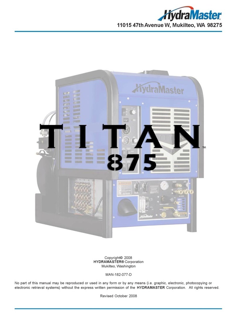
HydraMaster Titan 575 User manual

Titan 575
Owner’s Manual
HydraMaster
11015 47th Avenue West
Mukilteo, Washington 98275
MAN-44326 Rev. 0, September 1, 2011
(182-576-D)
No part of this manual may be reproduced or used in any form or by any means (i.e. graphic, electronic, photocopying or electronic
retrieval systems) without the express written permission of HydraMaster. Specications and information in this document are
subject to change without prior notice.
All rights reserved. © 2011 HydraMaster


i - Titan 575 Owner’s Manual
Table of Contents
GENERAL INFORMATION...........................................................................SECTION 1
System Concept...................................................................................... 1-3
Contact Information................................................................................. 1-4
Warnings, Cautions and Notices.............................................................1-5
Responsibilities.......................................................................................1-9
Machine Specications ........................................................................... 1-12
Optional Equipment.................................................................................1-14
Spare Parts.............................................................................................1-15
High Altitude Operation...........................................................................1-17
Local Water Precautions.........................................................................1-17
INSTALLATION INFORMATION...................................................................SECTION 2
Operating the Titan 575 In Hot Weather .................................................2-2
Setting Up the Titan 575.......................................................................... 2-5
Orientation of Fuel Pump........................................................................2-6
CLEANING INFORMATION.........................................................................SECTION 3
Precautions.............................................................................................3-1
Preparing the Carpet for Extraction.........................................................3-2
Rinse and Recover..................................................................................3-2
Overwetting.............................................................................................3-3
Streaking.................................................................................................3-3
Cleaning Tool Tips...................................................................................3-4
Severe Cleaning Situations..................................................................... 3-8
OPERATING INSTRUCTIONS.....................................................................SECTION 4
Setting the Temperature..........................................................................4-3
Start-up Procedure.................................................................................. 4-4
Setting the Pressure (for Optional High Pressure Washing Kit).............. 4-5
Shut Down Procedure............................................................................. 4-7
MACHINE MAINTENANCE.......................................................................... SECTION 5
Operational Maintenance........................................................................ 5-2
Overall Machine Maintenance.................................................................5-4
Engine Maintenance ............................................................................... 5-5
High Pressure Pump Maintenance ......................................................... 5-8
Vacuum System Maintenance ................................................................ 5-17
Descaling Procedure (Required)............................................................. 5-18
Freeze Guarding.....................................................................................5-19

Titan 575 Owner’s Manual - ii
WATER AND CHEMICAL SYSTEM............................................................. SECTION 6
ELECTRICAL SYSTEM................................................................................SECTION 7
Electrical System Information..................................................................7-1
SYSTEMS TROUBLESHOOTING............................................................... SECTION 8
Heating System....................................................................................... 8-2
Chemical System....................................................................................8-3
Engine..................................................................................................... 8-4
High Pressure System ............................................................................ 8-7
Vacuum System...................................................................................... 8-9
ASSEMBLIES AND PARTS LISTS...............................................................SECTION 9
Machine Assembly Parts List .................................................................9-2
Frame Assembly Parts List .................................................................... 9-11
Engine Assembly Parts List .................................................................... 9-15
Exhaust Assembly Parts List ..................................................................9-16
Top Cover Assembly Parts List .............................................................. 9-17
Flywheel Plate Assembly Parts List ....................................................... 9-19
Upper Dash Assembly Parts List ............................................................ 9-21
Electrical Panel Assembly Parts List ......................................................9-24
Blower Assembly Parts List.....................................................................9-26
Pump and Silencer Assembly Parts List .................................................9-27
Pump Assembly Parts List ......................................................................9-30
Water Box Assembly Parts List...............................................................9-32
Lower Dash Assembly Parts List............................................................. 9-35
Side Cover Assembly Parts List.............................................................. 9-36
Grill Assembly Parts List .........................................................................9-37
Blower Heat Exchanger Assembly Parts List.......................................... 9-40
Coolant Heat Exchanger Assembly Parts List......................................... 9-41
Diverter Valve Box Assembly Parts List..................................................9-42
By-Pass Valve Assembly Parts List.........................................................9-43
3-Way Valve Assembly Parts List............................................................ 9-44
Actuator Valve Assembly Parts List.........................................................9-45
Hi Pressure Manifold Assembly Parts List ..............................................9-46
70 Gallon Universal Recovery TankAssembly Parts List........................ 9-48
100 Gallon Universal Recovery TankAssembly Parts List...................... 9-50
70 Gallon Universal Recovery Tank for
85 Gallon Rotomolded TankAssembly Parts List.............................. 9-54
100 Gallon URT for 85 Gallon Rotomolded Tank Assembly Parts List ... 9-58
High Pressure Washing Kit - Pump Assembly Parts List........................9-60
High Pressure Washing Kit - Lower Left Dash Assembly Parts List .......9-61
Recovery Tank Cover with 2 1/2” Port KitAssembly Parts List............... 9-63
Hose Routings.........................................................................................9-64

iii - Titan 575 Owner’s Manual
HOW TO ORDER PARTS............................................................................ SECTION 10
Warranty Parts Orders ............................................................................ 10-1
Parts Orders............................................................................................ 10-1
Emergencies...........................................................................................10-1
WARRANTY INFORMATION.......................................................................SECTION 11
Blower ....................................................................................................11-1
High Pressure Water Pump ................................................................... 11-1
Vacuum Tank ..........................................................................................11-1
Chemical System....................................................................................11-1
Control Panel .........................................................................................11-1
Vacuum and Solution Hoses ..................................................................11-2
Cleaning Wand and Tool.........................................................................11-2
Water Heating System ............................................................................ 11-2
Hard Water Deposits............................................................................... 11-2
Warranty Procedure................................................................................11-2
ACCESSORIES AND CHEMICAL SOLUTIONS..........................................SECTION 12

Titan 575 Owner’s Manual - iv
List of Figures
Figure 1-1. Hard Water Map of Mainland United States.............................................1-18
Figure 2-1. Location of Roof Vents in Vehicle ..............................................................2-1
Figure 2-2. Recommended Location of Titan 575 in Van .............................................2-3
Figure 2-3. Install Fuel Pump, Outlet Side Up..............................................................2-6
Figure 2-4. Fuel Pump Must Be in Vertical Position.....................................................2-6
Figure 4-1. Titan 575 Upper Dash Assembly................................................................4-1
Figure 4-2. Titan 575 Lower Dash Assembly................................................................4-2
Figure 4-3. Heat Selector Valve....................................................................................4-3
Figure 4-4. Thermostat Dial..........................................................................................4-3
Figure 4-5. Location of Water Pressure Selector Valve ...............................................4-5
Figure 4-6. Location of Chemical System Switches.....................................................4-6
Figure 4-7. Location of Blower Lube Port on Lower Dash Assembly ...........................4-7
Figure 5-1. Remove Valve Cap and Valve Assembly...................................................5-9
Figure 5-2. Inspect Manifold and Old Valves................................................................5-9
Figure 5-3. Replace Center Inlet Check Valve With Modied Check Valve................5-10
Figure 5-4. Apply Grease and Install Valves...............................................................5-10
Figure 5-5. Replace Valve Capand Torque to 95 ft. lbs. (13 m kgs)...........................5-10
Figure 5-6. Separate Manifold from Crankcase..........................................................5-11
Figure 5-7. Seal Assemblies May Come Off with Manifold.........................................5-11
Figure 5-8. Examine Ceramic Plungers......................................................................5-11
Figure 5-9. Remove Stainless Steel Plunger Bolt and Ceramic Plunger ...................5-12
Figure 5-10. Install O-ring, Apply Sealant and Slide Plunger over Plunger Guide .....5-12
Figure 5-11. Extract Retainers and Seals...................................................................5-13
Figure 5-12. Seal Kit and Insertion Tool for Seal Installation......................................5-14
Figure 5-13. Install Seal Assembly Using O-Ring Grease..........................................5-14
Figure 5-14. Install Retainers into Cavities.................................................................5-15
Figure 5-15. Press Low Pressure Seal Assembly into Cavity.....................................5-15
Figure 5-16. Re-install Manifold and Torque Fasteners..............................................5-16
Figure 5-17. Torque Sequence in “X” Pattern.............................................................5-16
Figure 5-18. Torque Bolts to 22 ft. lbs (3 m kgs).........................................................5-16
Figure 5-19. Recirculation Fitting................................................................................5-18

v - Titan 575 Owner’s Manual
Figure 6-1. Annotated Water, Chemical and Solution Flow Diagram - View 1 of 3 ......6-3
Figure 6-2. Annotated Water, Chemical and Solution Flow Diagram - View 2 of 3 ......6-4
Figure 6-3. Annotated Water, Chemical and Solution Flow Diagram - View 3 of 3 ......6-5
Figure 6-4. Water, Chemical and Solution Flow Diagram - Larger View ......................6-6
Figure 6-5. Chemical Flow Diagram - Larger View.......................................................6-7
Figure 6-6. Exhaust Flow Diagram...............................................................................6-8
Figure 7-1. Electrical Schematic...................................................................................7-2
Figure 7-2. Wiring Diagram - View 1 of 3 .....................................................................7-3
Figure 7-3. Wiring Diagram - View 2 of 3 .....................................................................7-4
Figure 7-4. Wiring Diagram - View 3 of 3 .....................................................................7-5
Figure 9-1. Machine Assembly - View 1 of 4................................................................9-2
Figure 9-2. Machine Assembly - View 2 of 4................................................................9-3
Figure 9-3. Machine Assembly - View 3 of 4................................................................9-4
Figure 9-4. Machine Assembly - View 4 of 4................................................................9-5
Figure 9-5. Frame Assembly - View 1 of 5 ...................................................................9-6
Figure 9-6. Frame Assembly - View 2 of 5 ...................................................................9-7
Figure 9-7. Frame Assembly - View 3 of 5 ...................................................................9-8
Figure 9-8. Frame Assembly - View 4 of 5 ...................................................................9-9
Figure 9-9. Frame Assembly - View 5 of 5 .................................................................9-10
Figure 9-10. Engine Assembly - View 1 of 3...............................................................9-12
Figure 9-11. Engine Assembly - View 2 of 3...............................................................9-13
Figure 9-12. Engine Assembly - View 3 of 3...............................................................9-14
Figure 9-13. Exhaust Assembly..................................................................................9-16
Figure 9-14. Top CoverAssembly ..............................................................................9-17
Figure 9-15. Flywheel Plate Assembly .......................................................................9-18
Figure 9-16. Upper Dash Assembly............................................................................9-20
Figure 9-17. Electrical Panel Assembly - View 1 of 2.................................................9-22
Figure 9-18. Electrical Panel Assembly - View 2 of 2.................................................9-23
Figure 9-19. Blower Assembly....................................................................................9-25
Figure 9-20. Pump and Silencer Assembly ................................................................9-27
Figure 9-21. Pump Assembly - View 1 of 2 ................................................................9-28
Figure 9-22. Pump Assembly - View 2 of 2 ................................................................9-29
Figure 9-23. Water Box Assembly..............................................................................9-31
Figure 9-24. Lower Dash Assembly - View 1 of 2.......................................................9-33
Figure 9-25. Lower Dash Assembly - View 2 of 2.......................................................9-34
Figure 9-26. Side Cover - Machine Assembly............................................................9-36
Figure 9-27. Grill Assembly ........................................................................................9-37
Figure 9-28. Blower Heat Exchanger Assembly - View 1 of 2 ...................................9-38
Figure 9-29. Blower Heat Exchanger Assembly - View 2 of 2 ...................................9-39
Titan 575 Owner’s Manual - vi
Figure 9-30. Coolant Heat Exchanger Assembly........................................................9-41
Figure 9-31. Diverter Valve Assembly ........................................................................9-42
Figure 9-32. By-Pass Valve Assembly........................................................................9-43
Figure 9-33. 3-Way Valve Assembly...........................................................................9-44
Figure 9-34. Actuator Valve Assembly........................................................................9-45
Figure 9-35. Hi Pressure Manifold Assembly .............................................................9-46
Figure 9-36. 70 Gallon Universal Recovery Tank (URT) Assembly............................9-47
Figure 9-37. 100 Gallon Universal Recovery TankAssembly ....................................9-49
Figure 9-38. 70 Gallon URT for
85 Gallon Rotomolded TankAssembly - View 1 of 3...........................9-51
Figure 9-39. 70 Gallon URT for
85 Gallon Rotomolded TankAssembly - View 2 of 3...........................9-52
Figure 9-40. 70 Gallon URT for
85 Gallon Rotomolded TankAssembly - View 3 of 3...........................9-53
Figure 9-41. 100 Gallon URT for
85 Gallon Rotomolded TankAssembly - View 1 of 3...........................9-55
Figure 9-42. 100 Gallon URT for
85 Gallon Rotomolded TankAssembly - View 2 of 3...........................9-56
Figure 9-43. 100 Gallon URT for
85 Gallon Rotomolded TankAssembly - View 3 of 3...........................9-57
Figure 9-44. High Pressure Washing Kit - Pump Assembly.......................................9-59
Figure 9-45. High Pressure Washing Kit - Lower Left Dash Assembly ......................9-61
Figure 9-46. Recovery Tank Cover with 2 1/2” Port KitAssembly .............................9-62

1-1: General Information
The compact but powerful Titan™ 575 is a carefully re-engineered truckmount carpet
cleaning machine designed and manufactured by HydraMaster.AWG 972 Kubota engine
now powers the 575’s Tuthill 4007 Tri-Lobe vacuum blower and the high pressure water
pump, which is rated at 4 gpm (15 litres/minute).
In keeping with HydraMaster’s corporate philosophy to meet new lower emission
requirements, HydraMaster has re-designed the Titan 575 around the Kubota engine
which complies with two of the strictest emission regulations: EPA Phase3 and CARB
Tier3.
The Titan 575’s innovative design features include a blower/engine exhaust diverter
which allows for a non-recirculating or “dump-less” subsystem. This dump-less system,
a rst in the carpet cleaning industry, reduces the need to rell the fresh water tank or
empty the recovery tank.
1- General Information

General Information: 1-2
Other features of the Titan 575 are:
Dual oil bath and sight glasses for enhanced blower reliability• 0 - 1,200 psi (0 - 8,274 kPa) heated for carpet and tile cleaning• Optional 2,000 psi (13,790 kPa) pressure washing kit• Dual tool/wand capable• A.D.C temperature control with instant heat up to 265° F (129.4° C)• Optional Dura-Flow Automatic Pump Out (APO)• Optional 85 gallon Fresh Water Tank Mounting Kit•
TheTitan 575 can be mounted ontoaHydraMaster85 gallon (322 litre) RotomoldedFresh
WaterTank.You can also select eithertheHydraMaster70 gallon (265 litre) recoverytank,
which comes in the standard equipment package, or a 100 gallon (379 litre) recovery
tank, offered as an option.
ThisOwner’sManualcontainsinstallationandoperationinstructionsaswellasinformation
required for proper maintenance, adjustment and repair of the Titan 575. Component
troubleshooting guides have also been included for your convenience.
It is the purpose of this manual to help you properly understand, maintain and service
your Titan 575. Follow the directions carefully and you will be rewarded with years of
protable, trouble-free operation.
It is imperative that no section of this manual be overlooked when preparing for operation
of the Titan 575. Please read the manual to familiarize yourself with the operation of your
Titan 575, paying special attention to all Warnings and Cautions.
This section of the manual contains the following information:
Contact Information
Warnings, Cautions and Notices
Machine Specications
Responsibilities
Local Water Precautions
Photographs and illustrations included in this document can represent optional
equipment as well as standard equipment.

1-3: General Information
SYSTEM CONCEPT
This is how the Titan 575 works:
Incoming water enters the water box and is pressurized by the high pressure water
1. pump. The water is heated by engine coolant in the tube and shell heat exchanger
and then by the engine and blower exhaust in the cross ow heat exchanger.
Cleaning solution is then injected into the pressurized water stream and the heated
2. solution is delivered to the cleaning tool.
The solution is recovered by the vacuum generated by the vacuum pump and is
3. collected in the recovery tank for proper disposal.
Engine
Vacuum Blower
Water Box
Heat
Exchangers
Silencer
Water Pump

General Information: 1-4
CONTACT INFORMATION
If you have any questions regarding the operation, maintenance or repair of this machine,
please contact your local distributor.
To nd a local distributor, please visit our website at http://hydramaster.com/HowToBuy/
DealerLocator.aspx
If your question cannot be resolved by your distributor or by the information within this
manual, you may contact HydraMaster Customer Service direct using the following phone
numbers.
Hours Telephone Numbers E-mail Addresses
Monday-Friday (425) 775-7275 Service Tech Support:
techsupport@hydramaster.com
7:00 a.m. to 5:00 p.m. (425) 775-7276 Parts Parts Support:
parts@hydramaster.com
Pacic Standard Time (425) 771-7156 Parts /
Service FAX
When calling your distributor, be sure to reference the serial number and date of
purchase.
FOR YOUR REFERENCE:
Serial No.____________________________________________________
Date of Purchase:_____________________________________________
Purchased From (Distributor): __________________________________

1-5: General Information
WARNINGS, CAUTIONS AND NOTICES
HydraMaster uses this WARNING symbol throughout the manual to warn of
possible injury or death.
This CAUTION symbol is used to warn of possible equipment damage.
This NOTICE symbol indicates that federal or state regulatory laws may apply,
and also emphasizes supplemental information.

General Information: 1-6
Warnings and Cautions specic to the Titan 575 include the following:
During the operation of the truckmount many components are in motion. Never
touch any part of the truckmount that is in motion. Serious injury may result.
During the operation of the truckmount many surfaces will become extremely hot.
Never touch hot surfaces. Serious injury may result.
The operation of this truckmount can produce noise levels exceeding 85 decibels
to a distance of 10 ft (3.05 m). The Occupational Safety and HealthAdministration
(OSHA) recommends the use of hearing protective equipment if a person is
exposed to an average of 85 decibels over an 8-hour period. Check with local
and state agencies concerning hearing conservation rules.
During the operation of the truckmount carbon monoxide and other toxic fumes
are produced. Position the vehicle so that any fumes produced will be directed
away from inhabited areas and any points of building entry (doors, windows, air
conditioning units, fans, etc.). Do not occupy the vehicle while the truckmount is
in operation. Serious injury may result.
Duringtheoperation of the truckmount, chemicals knowntotheStateofCalifornia
to cause cancer, birth defects and other reproductive harm are produced by the
engine exhaust.
Never operate the truckmount with a portable gas container inside the vehicle.
Doing so will increase the risk of re and explosion. Serious injury or death may
result.
Transportingaventedfuelcontainerthatpresentlycontains,orhasevercontained
in the past, a ammable liquid is strictly forbidden by HydraMaster and by federal
and state regulations. Doing so will increase the risk of re and explosion. Serious
injury or death may result.

1-7: General Information
Never smoke in or around the truckmount. Doing so will increase the risk of re
and explosion. Serious injury or death may result.
During the operation of the truckmount the exhaust system will become extremely
hot. Keep all ammable materials away from the truckmount exhaust system.
Failure to do so will increase the risk of re and explosion. Serious property
damage may result.
Never operate the truckmount when the vehicle is tilted more than 10 degrees in
anydirection.Doingsowillresultinimproperlubricationoftheinternalcomponents,
and will increase the risk of serious component or engine damage.
Never perform cleaning operations when the truckmount engine is running at the
IDLE throttle position. Failure to do so will increase the risk of serious component
or engine damage.
Never operate the truckmount with the vehicle doors closed. Doing so results in
extremelyhightemperaturesinsidethevehicle and will lead toseriouscomponent
or engine damage.
Neveruseconcentratedacidsorsolvents(includingd-limonene)inthetruckmount
water system or chemical system. Use of these products will cause serious
component damage.
Neveroperatethetruckmountwithawaterhardnessreadingmeasuring3.0grains
per gallon (3.79 litres) or higher. Using reading than 3.0 grains per gallon (3.79
litres) will cause scale to build up inside the truckmount water system. Scale build
up causes serious component damage. Test all water prior to use and use water
softening equipment if necessary.

General Information: 1-8
Never allow water to freeze inside the truckmount. Serious component damage
will occur. Perform all freeze guarding procedures outlined in this digital Owner’s
Manual.
Many vehicles have critical components mounted directly below the oor that
can easily be damaged. Before drilling holes in the oor of the vehicle inspect
the underside of the vehicle for critical components. Failure to do so may result
in damage to the vehicle.
Use of the vacuum recovery system when stripping or otherwise removing wax
from oors is specically excluded as an approved use of the truckmount. Failure
to follow this exclusion may lead to component failure and will invalidate your
warranty.
Use of the vacuum recovery system for “dry cleaning”, without corresponding
solution application (i.e. duct cleaning), is specically excluded as an approved
use of the truckmount. Failure to follow this exclusion may lead to component
failure and will invalidate your warranty.
If concentrated acids or solvents are used to pre-treat surfaces before power
washing, do not recover them through the vacuum system. Failure to follow this
exclusion may lead to component failure and will invalidate your warranty.

1-9: General Information
RESPONSIBILITIES
Purchaser’s Responsibilities
Prior to purchasing a van, ensure that the payload is suitable for all of the equipment• thatwillbeinstalled andtransported.Thisincludesandisnotlimitedto:thetruckmount,
recovery tanks, fresh water tanks, on-board water, hose reels, hoses, cleaning tools,
chemicals and drying equipment. Payload capacity information is available through
the auto dealer, the manufacturer’s web site, and is also located on the door pillar of
the driver’s side door.
Purchase a heavy duty Group 24 (500+ CC Amps) battery for this truckmount. This is
• normally available from the installation dealer.
Prior to dropping your van off at the distributor for the truckmount to be installed, have
•
a spray-on bed liner applied to the oor such as Rhino Lining® or Line-X®.
Plywood and carpet are not recommended.
Prior to operating the truckmount, read this manual in its entirety and familiarize• yourself with the information contained here. Special attention should be paid to all
Warnings and Cautions.
The distributor is responsible for the correct installation of the truckmount. The
• distributor is also responsible to train you in the correct and proper operation and
maintenance of the truckmount.
Any modication of the truckmount may void the warranty.

General Information: 1-10
Distributor’s Responsibility
Acceptance of Shipment
Before accepting the truckmount, check the following:
The truckmount should be free from any damage during shipping. Do not sign the1. delivery receipt until you have closely inspected the truckmount and noted any
damageonthedeliveryreceipt.Hiddendamagemaybepresenteveniftheboxlooks
okay. It is recommended that the box be opened before you sign for the shipment.
Check the packing list and verify that all items are accounted for.
2.
Installation Responsibilities
Ensure proper payload capacity. It is the distributor’s responsibility to verify that the• equipment package does not exceed the vehicle capacity.
Ensure installation of a safe fuel tap system and through-oor ttings as provided by
• HydraMaster.
Ensure proper placement of the truckmount, recovery tank, fresh water tank, and• accessories in the vehicle, and check that they are secured with bolts and back up
plates. The distributor should verify that the owner is in agreement with the layout.
Ensure proper connection of the fuel lines.• Ensure proper connection and installation of the battery. Verify that the battery is in• accordance with HydraMaster’s recommendation.
Check the pump, vacuum blower and engine oil levels prior to starting the
• truckmount.
Start and run the truckmount and check that all systems function properly.
• Test all hoses, wands and other accessories for correct operation.• Ensure timely return of the document package.•

1-11: General Information
Training
The distributor should provide a thorough review of the operation manual with the
purchaser along with instruction and familiarization in:
How all the truckmount’s systems function.
1. All safety precautions and their importance.2. How to correctly start and shut down the truckmount.3. How to correctly clean with the truckmount.4. Where and how often to check and change component oil levels.5. Freezing damage and how to avoid it. This includes explaining proper freeze6. guarding procedures.
How to do basic troubleshooting of the truckmount.
7. Hard water damage and how to avoid it. This includes how to determine if hard8. water exists in your area and the installation and use of water softening systems.
The truckmount’s warranty and warranty procedures.
9.

General Information: 1-12
MACHINE SPECIFICATIONS
Frame Dimensions 26.0" W x 45" D x 39" H
(66 cm x 114 cm x 99 cm)
Weight 900 lbs (408 kg)
Engine - WG 972 Kubota Oil Type 5W-30 Synthetic
Capacity 3.2 quarts (3.02 litres)
when changing oil and lter
Engine rpm High - 3,000 rpm
Idle - 1,500 rpm
Fuel Consumption 1.6 gph (6.1 litres/hr)
Ignition Keyless
Vacuum Blower - Tuthill
4007 Competitor (Dual
Splash Lubrication)
Oil Type
Max. Vac. 12” Hg PneuLube or other ISO 100
rating
Gear End Capacity Approx. 5.8 oz. (171.5 ml)
Drive End Capacity Approx. 4.7 oz. (139 ml)
Blower rpm 3,000 rpm
Water Pump- General
Pump Oil Type 15W-40
Capacity 14 oz (414 ml).
Pump Rate 4.0 gpm (15 litres/minute)
Pump rpm 1,700 rpm
Operating Pressure 0 - 1,200 psi (heated)
(0 - 8,274 kPa) 0 - 2,000 (no heat)
(0 - 13,790 kPa) *
Chemical System Last Step Chemical
Injection
Heating System Cross Flow Heat
Exchanger CopperTubeandShellHeat
Exchanger
* Pressure washing option
Other manuals for Titan 575
2
Table of contents
Other HydraMaster Vacuum Cleaner manuals

HydraMaster
HydraMaster Titan 575 User manual

HydraMaster
HydraMaster CDS xDrive User manual

HydraMaster
HydraMaster Boxxer 427 User manual

HydraMaster
HydraMaster Titan 875 User manual

HydraMaster
HydraMaster drimaster User manual

HydraMaster
HydraMaster GTXR+ User manual

HydraMaster
HydraMaster Boxxer 421 User manual

HydraMaster
HydraMaster ChemDry CTS 4600 CDS User manual

HydraMaster
HydraMaster CDS 4.8 User manual

HydraMaster
HydraMaster Chem-Dry PowerHead User manual