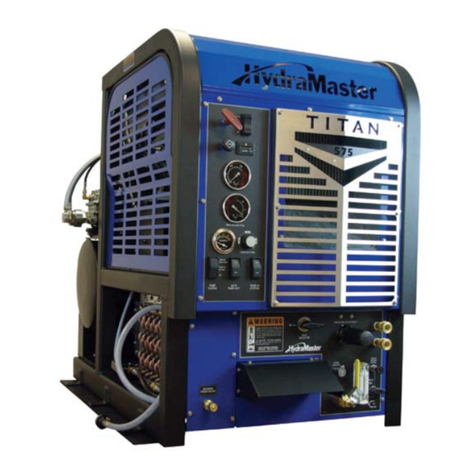
HydraMaster Titan 875 User manual

Copyright© 2008
HYDRAMASTER® Corporation
Mukilteo, Washington
MAN-182-077-D
No part of this manual may be reproduced or used in any form or by any means (i.e. graphic, electronic, photocopying or
electronic retrieval systems) without the express written permission of the HYDRAMASTER Corporation. All rights reserved.
Revised October 2008
11015 47th Avenue W, Mukilteo, WA 98275

ii - Titan Owner’s Manual
GENERAL INFORMATION ........................................................................... Section 1
Contact Information ........................................................................... 1-2
Warnings, Cautions, and Notices ...................................................... 1-3
Responsibilities ................................................................................. 1-7
Fuel Pump Installation Guidelines ...................................................... 1-10
Vehicle Preparation ........................................................................... 1-12
High Altitude Operation...................................................................... 1-16
Local Water Precautions ................................................................... 1-17
CLEANING AND CHEMICALS .................................................................... Section 2
Precautions ....................................................................................... 2-2
Preparing the Carpet for Extraction ................................................... 2-2
Rinse and Recover ............................................................................ 2-3
Over-Wetting ..................................................................................... 2-4
Streaking ........................................................................................... 2-4
SYSTEM OPERATION ................................................................................. Section 3
Machine Specifications ..................................................................... 3-2
Spare Parts List ................................................................................ 3-3
Operating Instructions ........................................................................ 3-4
Setting the Temperature ..................................................................... 3-6
Machine Safeties .............................................................................. 3-7
MACHINE MAINTENANCE.......................................................................... Section 4
Operational Maintenance .................................................................. 4-2
Overall Machine Maintenance ............................................................ 4-4
Engine Maintenance.......................................................................... 4-5
High Pressure Pump Maintenance .................................................... 4-8
Vacuum System Maintenance............................................................ 4-27
De-scaling Procedure (Required) ...................................................... 4-28
Freeze Guarding ............................................................................... 4-29
WATER AND CHEMICAL SYSTEM ............................................................. Section 5
Water and Chemical Flow Operation ................................................. 5-2
Flow Diagrams.................................................................................. 5-3
Table of Contents

iii - Titan Owner’s Manual
ELECTRICAL SYSTEM ............................................................................... Section 6
Electrical System Information ............................................................. 6-2
Electrical Schematic.......................................................................... 6-3
Wiring Diagram ................................................................................. 6-4
TROUBLESHOOTING ................................................................................. Section 7
Heating System ................................................................................. 7-2
Chemical System .............................................................................. 7-3
Engine .............................................................................................. 7-4
High Pressure System ....................................................................... 7-6
Vacuum System ................................................................................ 7-8
MACHINE ASSEMBLIES AND PARTS LIST ................................................ Section 8
Machine Hose Routings..................................................................... 8-75
HOW TO ORDER PARTS ............................................................................ Section 9
Warranty Parts Orders ....................................................................... 9-2
Parts Orders...................................................................................... 9-2
Emergencies..................................................................................... 9-2
One Final Note .................................................................................. 9-3
WARRANTY INFORMATION ........................................................................ Section 10
Blower ............................................................................................... 10-2
High Pressure Pump ......................................................................... 10-2
Vacuum Tank ..................................................................................... 10-2
Chemical System .............................................................................. 10-2
Control Panel .................................................................................... 10-2
Vacuum and Solution Hoses .............................................................. 10-3
Cleaning Wand.................................................................................. 10-3
Water and Heating Systems .............................................................. 10-3
Hard Water Deposits......................................................................... 10-3
Warranty Procedure........................................................................... 10-4
ACCESSORIES .......................................................................................... Section 11
Genuine HydraMaster Accessories and Detergents ........................... 11-1

iv - Titan Owner’s Manual
MACHINE MAINTENANCE.......................................................................... Section 4
Fig. 4-1 Recirculation Fitting .............................................................. 4-2
WATER AND CHEMICAL SYSTEM ............................................................. Section 5
Fig. 5-1 Water Flow Diagram (Sheet 1) ............................................. 5-3
Fig. 5-2 Water Flow Diagram (Sheet 2) ............................................. 5-4
Fig. 5-3 Water Flow Diagram (Sheet 3) ............................................. 5-5
ELECTRICAL SYSTEM ............................................................................... Section 6
Fig. 6-1 Electrical Schematic ............................................................. 6-3
Fig. 6-2 Wiring Diagram (Sheet 2)..................................................... 6-4
Fig. 6-3 Wiring Diagram (Sheet 3)..................................................... 6-5
Fig. 6-4 Wiring Diagram (Sheet 4)..................................................... 6-6
MACHINE ASSEMBLIES AND PARTS LIST ................................................ Section 8
Fig. 8-1 Machine Assembly - Front Left View ..................................... 8-3
Fig. 8-2 Machine Assembly - Front Right View ................................... 8-4
Fig. 8-3 Machine Assembly - Back Right View ................................... 8-5
Fig. 8-4 Machine Assembly - Back Left View ..................................... 8-6
Fig. 8-5 Frame Assembly - Front Right View ...................................... 8-8
Fig. 8-6 Frame Assembly - Front Left View ........................................ 8-9
Fig. 8-7 Frame Assembly - Back Right View ...................................... 8-10
Fig. 8-8 Engine Assembly - Front View .............................................. 8-12
Fig. 8-9 Engine Assembly - Back Right View ..................................... 8-13
Fig. 8-10 Engine Assembly - Back Left View ..................................... 8-14
Fig. 8-11 Engine Assembly - Back Left View - Detail ......................... 8-15
Fig. 8-12 Solenoid Assembly View .................................................... 8-18
Fig. 8-13 Idler Pulley Tensioner Assembly .......................................... 8-20
Fig. 8-14 Blower Assembly - Front View ............................................ 8-22
Fig. 8-15 Blower Assembly - Back View ............................................ 8-23
Fig. 8-16 Air Actuator Assembly......................................................... 8-25
Fig. 8-17 Pump & Silencer Assembly ................................................ 8-27
Fig. 8-18 Pump Assembly - Back View .............................................. 8-29
Fig. 8-19 Pump Assembly - Front View .............................................. 8-30
Fig. 8-20 Exhaust Assembly .............................................................. 8-32
Fig. 8-21 Blower Heat Exchanger Assembly ...................................... 8-34
Fig. 8-22 Coolant Heat Exchanger Assembly..................................... 8-36
Fig. 8-23 Panel, Lower Instrument Assembly - Front View .................. 8-38
Fig. 8-24 Panel, Lower Instrument Assembly - Back Left View ........... 8-39
List of Figures
v - Titan Owner’s Manual
Fig. 8-25 Panel, Lower Instrument Assembly - Back Right View ......... 8-40
Fig. 8-26 PSI Regulator Valve 0-3200 PSI Assembly ......................... 8-43
Fig. 8-27 Orifice Manifold Assembly .................................................. 8-45
Fig. 8-28 Hi-Pressure Out Manifold Assembly.................................... 8-47
Fig. 8-29 3 Way Valve Assembly........................................................ 8-49
Fig. 8-30 2 Way Valve Assembly........................................................ 8-50
Fig. 8-31 Poly Water Box 8G Assembly ............................................. 8-51
Fig. 8-32 Diffuser Assembly .............................................................. 8-53
Fig. 8-33 Upper Dash Assembly........................................................ 8-54
Fig. 8-34 Inset Dash Assembly .......................................................... 8-56
Fig. 8-35 Grill Dash Assembly ........................................................... 8-58
Fig. 8-36 Electrical Panel Assembly .................................................. 8-60
Fig. 8-37 Cover, Catalytic Assembly .................................................. 8-62
Fig. 8-38 Top Cover Machine Assembly............................................. 8-64
Fig. 8-39 Left Side Cover Machine Assembly .................................... 8-66
Fig. 8-40 Right Side Cover Machine Assembly .................................. 8-67
Fig. 8-41 100 Gallon Universal Recovery Tank Assembly ................... 8-68
Fig. 8-42 Cover, 100 Gallon Universal Recovery Tank Assembly ........ 8-71
Fig. 8-43 Vacuum Relief Valve Assembly ........................................... 8-72
Fig. 8-44 Dura-Flow APOAssembly .................................................. 8-73
LIST OF FIGURES CONT.
REFERENCE DOCUMENTS
Tuthill Blower Competitor Manual
GM PSI Operation and Maintenance Manual

1-2: General Information
Hours
Monday - Friday
7:00 am to 5:00 pm
PACIFIC STANDARD TIME
Telephone Numbers
(425) 775-7276 Parts
(425) 775-7275 Service
(800) 426-4225 Parts / Service FAX
Contact Information

1-3: General Information
Warnings, Cautions, and Notices
This symbol indicates a situation which, if not avoided, could result in death or serious
injury.
This symbol indicates a hazardous situation which, if not avoided, could result in dam-
age to the truck mount.
This symbol indicates that federal or state regulatory laws may apply.

1-4: General Information
During the operation of the truck mount many components are in motion. Never touch
any part of the truck mount that is in motion. Serious injury may result.
During the operation of the truck mount many surfaces will become extremely hot.
Never touch hot surfaces. Serious injury may result.
The operation of this truck mount can produce noise levels exceeding 85 decibels to a
distance of 10 feet. The Occupational Safety and Health Administration (OSHA) recom-
mends the use of hearing protective equipment if a person is exposed to an average of
85 decibels over an eight hour period. Check with local and state agencies concerning
hearing conservation rules.
During the operation of the truck mount carbon monoxide and other toxic fumes are
produced. Position the vehicle so that any fumes produced will be directed away from
inhabited areas and any points of building entry (doors, windows, air conditioning units,
fans, etc.). Do not occupy the vehicle while the truck mount is in operation. Serious
injury may result.
During the operation of the truck mount chemicals known to the State of California to
cause cancer, birth defects and other reproductive harm are produced by the engine
exhaust.

1-5: General Information
Never operate the truck mount with a portable gas container inside the vehicle. Doing
so will increase the risk of fire and explosion. Serious injury or death my result.
Transporting a vented fuel container that presently contains, or has ever contained in
the past, a flammable liquid is strictly forbidden by HydraMaster and by federal and
state regulations. Doing so will increase the risk of fire and explosion. Serious injury or
death my result.
Never smoke in or around the truck mount. Doing so will increase the risk of fire and
explosion. Serious injury or death may result.
During the operation of the truck mount the exhaust system will become extremely hot.
Keep all flammable materials away from the truck mount exhaust system. Failure to do
so will increase the risk of fire and explosion. Serious property damage may result.
Never operate the truck mount when the vehicle is tilted more than 10 degrees in any
direction. Doing so will result in improper lubrication of the internal components, and will
increase the risk serious component or engine damage.
Never perform cleaning operations when the truck mount engine is running at the IDLE
throttle position. Failure to do so will increase the risk of serious component or engine
damage.

1-6: General Information
Never operate the truck mount with the vehicle doors closed. Doing so results in ex-
tremely high temperatures inside the vehicle and will lead to serious component or
engine damage.
Never use concentrated acids or solvents (including d-limonene) in the truck mount
water system or chemical system. Use of these products will cause serious component
damage.
Never operate the truck mount with a water hardness reading measuring 3.0 grains per
gallon or higher. Using reading than 3.0 grains per gallon will cause scale to build up
inside the truck mount water system. Scale build up causes serious component dam-
age. Test all water prior to use and use water softening equipment if necessary.
Never allow water to freeze inside the truck mount. Serious component damage will
occur. Perform all freeze guarding procedures outlined in this digital Owner’s Manual.
Many vehicles have critical components mounted directly below the floor that can easily
be damaged. Before drilling holes in the floor of the vehicle inspect the underside of the
vehicle for critical components. Failure to do so may result in damage to the vehicle.

1-7: General Information
Responsibilities
THE PURCHASER’S RESPONSIBILITIES
· Prior to purchasing a van, ensure that the payload is suitable for all of the
equipment that will be installed and transported. This includes and is not
limited to: the truck mount, recovery tanks, fresh water tanks, on-board
water, hose reels, hoses, cleaning tools, chemicals, drying equipment, etc.
Payload capacity information is available through the auto dealer, the
manufacturer’s web site, and is also located on the door pillar of the
driver’s side door.
· Purchase a heavy duty Group 24 battery for this truck mount. This is
normally available from the installation dealer.
· Prior to dropping your van off at the distributor for the truck mount to be
installed, have a spray-on bed liner applied to the floor such as Rhino
Lining® or Line-X®.
· Prior to operating the truck mount read this manual in its entirety and
familiarize yourself with the information contained here. Special attention
should be paid to all cautions and warnings.
· The distributor is responsible for the correct installation of the truckmount.
The distributor is also responsible to train you in the correct and proper
operation and maintenance of the truck mount.
Any modification of the truck mount may void the warranty.

1-8: General Information
THE DISTRIBUTOR’S RESPONSIBILITY
Acceptance of Shipment
Before accepting the truck mount, check the following:
· The truck mount should be free from any damage during shipping. Do not
sign the delivery receipt until you have closely inspected the truck mount
and noted any damage on the delivery receipt. Hidden damage may be
present even if the box looks okay. It is recommended that the box be
opened before signing for the shipment.
· Check the packing list and verify that all items are accounted for.
Installation Responsibilities
· Ensure proper payload capacity. It is the distributor’s responsibility to
verify that the equipment package does not exceed the vehicle capacity.
· Ensure installation of a safe fuel tap system and through-floor fittings as
provided by HydraMaster.
· Proper placement of the truck mount, recovery tank, fresh water tank, and
accessories in the vehicle and securing them with bolts and back up
plates. The distributor should verify that the owner is in agreement with
the layout.
· Proper connection of the fuel lines.
· Proper connection and installation of the battery. Verify that the battery is
in accordance with HydraMaster’s recommendation.
· Check the pump, vacuum blower and engine oil levels prior to starting the
truck mount.
· Start and run the truck mount and check that all systems function properly.
· Test all hoses, wands, etc. for correct operation.
· Timely return of the document package.

1-9: General Information
Training
The distributor should provide a thorough review of the operation manual with the pur-
chaser along with instruction and familiarization in:
· How all the truck mount’s systems function.
· All safety precautions and their importance.
· How to correctly start and shut down the truck mount.
· How to correctly clean with the truck mount.
· Where and how often to check and change component oil levels.
· Freezing damage and how to avoid it. This includes explaining proper
freeze guarding procedures.
· How to do basic troubleshooting of the truck mount.
· Hard water damage and how to avoid it. This includes how to determine if
hard water exists in your area and the installation and use of water soften-
ing systems.
· The truck mount’s warranty and warranty procedures.

1-10: General Information
Fuel Pump Installation Guidelines
General
The 1.6L GM engine on the Titan is Fuel Injected; this is a high pressure system and
requires approved components and hose to operate within the specifications. The
average operating pressure at the fuel rail should be 40-50 PSI. This pressure is con-
trolled via an pressure manifold that is placed inline with the fuel pump. The fuel sys-
tem should be hooked up in the following order:
1. Fuel Tank Tap
2. Fuel Pump
3. Fuel Filter
4. Fuel Pressure Manifold
5. Through Floor Kit
6. Machine
The fuel pump has a “domed” end and an end with the electrical terminations. The
“domed” end is the inlet of the pump and the side with the terminations is the output.
The fuel pressure manifold has three ports. The side with the two ports is the return
and the inlet, the side with the single port is the output. The dual port side has one
connection almost in the center of the block, this is the inlet. The connection that is
slightly offset is the return to the fuel tank. The electrical plug must be positioned at the
top when the manifold is installed.
The supplied fuel quick connects are required per the engine certification requirements.
The fuel hose is specific to the Titan, this is required by the EPA to maintain the engine
certification as well as the pressure requirements.
Locating Components
The Titan is equipped with a fuel pump mounting bracket assembly. This bracket
should be located as close to the fuel source as possible. It should be oriented so the
fuel pressure manifold plug is oriented upwards. (see Figure 1-1)

1-11: General Information
Precautions:
Failure to use specified fuel hose can result in equipment failure or bodily injury.
Fuel hose specification: Fuel injection hose carb no. C-4-06-002 SAE 30R9 180 PSI
The fuel filter must be on the outlet side of the pump, failure to do so may cause the
engine to run poorly.
It is important that the order of the fuel supply components are installed correctly, failure
to do so may cause the engine or fuel components may not function properly or be
damaged.
Failure to use this hose can result in non-compliance fines set forth by the EPA.
All components should be replaced with approved OEM parts.
Figure 1-1. Fuel Pump Diagram

1-12: General Information
Vehicle Preparation
When selecting a truck, remember the preferable vehicle for a Titan 875 installation is a
cargo van with a heavy-duty suspension package and a 3/4 HD ton capacity. If a fresh
water tank is added, a one ton or larger capacity van is required.
TRUCK PREPARATION
The manufacturer recommends the installation of a spray-on bed liner in the vehicle
prior to installation of machine.
This provides ‘metal to cushion’ mounting rather than ‘metal to metal’ and makes for an
attractive van interior. It is highly recommended to install roof vents in vehicles operated
in hot weather locations. Roof vent positions are shown in Figure 1-2.
Be cautious when drilling any holes through the van floor. Many vans have
critical components mounted directly below the van floor that could be
damaged by a misplaced drill bit.
Figure 1-2. Roof Vent

1-13: General Information
Figure 1-3. Recommended Placement
Placement of Unit in Vehicle
There are two recommended unit placements:
SIDE DOOR
Most installations are side door. This provides rear access for accessories and hoses
as well as unobstructed access to the component/working side of the machine, thus
making it a bit easier to perform maintenance and/or repair without removing the unit
from the truck.
REAR DOOR
Although this location partly limits working access, it does direct the noise away from
the cleaning site. Some cleaners in the colder areas prefer this location because it puts
the weight over the rear wheels for better traction in ice and snow. Rear mounting
requires the unit to be slid to the right side as far as possible.
This not only provides adequate working space on the component side of the unit but
also improves weight distribution inside the van (engine and component weight line up
over drive shaft). Also, it is physically easier to load the unit into the rear door due to
the height of the van bed.

1-14: General Information
Machine Tie Down Cleats
Secure the machine to the floor of the van with the six tie down cleats provided. This
safety measure will ensure that the machine will not slide inside the van. See the fol-
lowing illustration for the correct installation.
Ensure that the machine is well secured to the floor of the van with the hardware sup-
plied. A sudden or crash stop will cause the machine to rocket forward. Protect your-
self and the machine. SECURE IT!
Figure 1-4. Installation Using Tie-down Cleats
It is recommended by the manufacturer that the exhaust from the front of the machine
be vented down under the truck to prevent carbon monoxide from entering the job site.
Always park the truck so the exhaust is blowing away from the job site.
The manufacturer also recommends the installation of aluminum vents in the truck roof
to allow heat to escape.

1-15: General Information
Never operate this machine with a portable gas can inside the truck. Doing so in-
creases the risk of a fire or explosion.
Mount a fire extinguisher just inside the rear or side door for emergencies.
Do not use a portable propane tank inside of the truck or van. It is dangerous and
illegal in most states.
Transportation in a vehicle of any vented fuel container that presently holds or has ever
held a flammable liquid is strictly forbidden by HydraMaster Corporation and by federal
and state regulation.
The engine exhaust from this product contains chemicals known to the State of Califor-
nia to cause cancer, birth defects or other reproductive harm.
Other manuals for Titan 875
1
Table of contents
Other HydraMaster Vacuum Cleaner manuals

HydraMaster
HydraMaster Titan 575 User manual

HydraMaster
HydraMaster ChemDry CTS 4600 CDS User manual

HydraMaster
HydraMaster drimaster User manual

HydraMaster
HydraMaster CDS xDrive User manual

HydraMaster
HydraMaster Boxxer 421 User manual

HydraMaster
HydraMaster CDS 4.8 User manual

HydraMaster
HydraMaster GTXR+ User manual

HydraMaster
HydraMaster Titan 575 User manual

HydraMaster
HydraMaster hydramaster User manual

HydraMaster
HydraMaster Chem-Dry PowerHead User manual