10 III @
6. Assembly & Installation
AUTOMATING ROLL-UP DOORS
(Not roller-shutter)
6. Assembly & Installation
11
III @
Mounting (cont.)
Position the door-mount brackets, one near the edge of the door and one at the end of the
crossbar, and rivet them to the bottom member of the door.
Pull the manual release cord (which should be shortened to about 50mm) and open the door
fully by hand. With the door open, mark, drill and secure the wall-bracket to the wall.
Tighten the setscrews of the wall-mount bracket.
Important! Springs to be greased, regularly checked and adjusted. If necessary, contact an
Accredited Hydro Doors Installer.
Fig.4
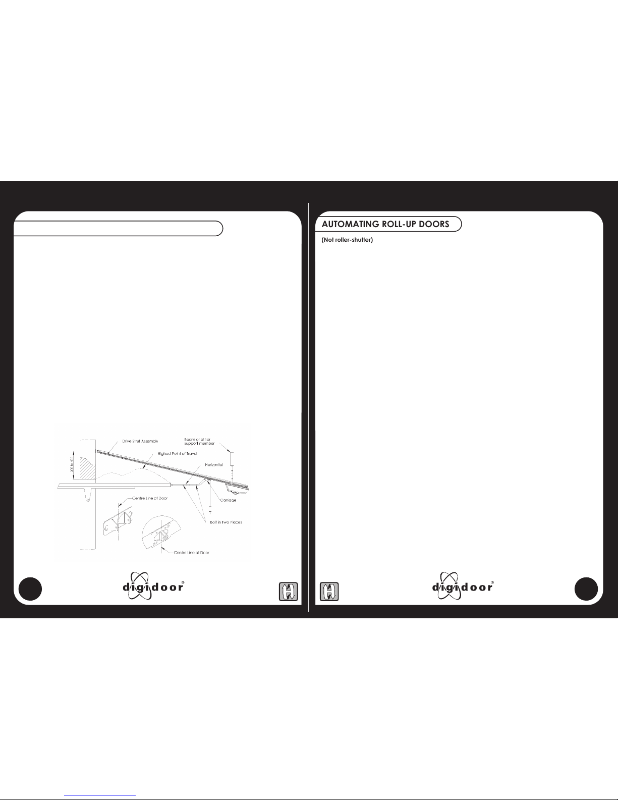
AUTOMATING A TRACKLESS ONE-PIECE DOOR
(Tipup Doors, Single and Double)
Extend and mark the vertical centre line of the door on the wall above the door. Make a mark on
the centre line between 300mm and 400mm above the door.
Place the Anchor Bracket on the wall and align the bracket. Mark the position of the mounting
holes, and secure the anchor bracket to the wall. Important! The anchor bracket handles all the
operating forces.
Secure the foot-end of the Drive Strut assembly to the anchor bracket while supporting the motor
end.
Open the door and vertically align the Drive Strut assembly to the door centre line. While supporting
the motor, ensure that the door's highest point of travel clears the Drive Strut assembly. Determine
the length of the hanging bracket needed to make a triangular fixing. Fit the hanging brackets to
align with a joist, batten or concrete member, as close to the power head as is conveniently
possible. Note! The Hanging Brackets may be angled forwards or backwards, and secured to either
the front or rear mounting lugs.
With the door closed, pull the carriage release cord. Mount the door bracket securely to the top
edge of the door on the centre line. Connect the curved door arm to the carriage and the straight
door arm to the door bracket. Caution! With the door in the closed position, slide the carriage
towards the door and overlap the connecting door arms such that the arms form roughly a 45°
angle to the door, and securely bolt them in two places.
With the door in the open position, move the Open Stop up against the Carriage and secure it in
place by means of the Self-Drilling screw provided. Then connect the Open Limit cable to the plug
on the Operator as in Fig 3, Step 2 on p9. Ensure the hook and clip on the plugs are aligned before
connecting.
Refer to Electrical Connections and Set-up, Page 12
Fig.3
Note! This requires a special Roll-up Kit, which is intended for automating single doors as well as two
side-by-side doors, separated by a column of not more than 600mm. The kit suits most popular makes of
roll-up doors.
Before You Start!
Check that the shaft of the roll-up door is level. Ensure that the sidetracks are clean (free of grease and dirt)
and undamaged (no bends or dents). Loosen the sidetracks and move them to create ample side-clearance
between the edge of the door and the inside of the track, and re-tighten the fixing bolts. With the door fully
closed, check that the large springs on the shaft over-head are well greased. This is important! Check the
balance of the door. Ideally, when the door is moved by hand and left at any point, it should not rise or fall.
Adjust the springs if necessary. Caution! Spring adjustment can be dangerous! If unsure how to proceed,
consult the door supplier or an accredited door installer. Then connect the Open Limit cable to the plug on the
Operator as in Fig 3, Step 2 on p9. Ensure the hook and clip on the plugs are aligned before connecting.
Assembly of the digidoor III ac/dc Power Head to the Strut
1. Ensure that the bullet fitting in the chain drive is about in the middle of the Strut.
2. With the open side of the Drive Strut assembly upwards (chain visible), align the motor shaft with
the sprocket and fit the strut so that the motor shaft passes through the hole in the strut. Secure
the strut to the power-head with M6 bolts in the upper and lower positions. See fig. 4 on Page 12.
Important! Reverse the Motor Direction.
Remove the Light and the outer cover from the Power Head and locate the two Screw connecters
in the motor wires. Swap the motor wires from red/red, green/grey to red/grey, green/red.
Assembly of the Roll-up Kit
The Roll-up kit consists of a wall-mount bracket, a “T”-piece, a crossbar, four door-mount brackets
and a pack of 'Pop' rivets. Fit the anchor bracket to the foot-end of the Drive Strut assembly. Secure
the wall-mount bracket to the Power-head. Fit the flat bar of the 'T' –piece to the carriage and
secure it with the M8 Bolt and Nyloc nut provided. Slide the crossbar through the 'T' -piece and
place a door-mount bracket on each end of the crossbar, or two door-mount brackets in the case
of a single door, one near the edge of the door and the other at the end of the crossbar.
Mounting
Stand the unit next to the door and lean it against the wall. Position the doors at the same level as
the crossbar. With the anchor bracket centered, move the unit towards the wall until the door-
mounts touch the door. Mark the mounting holes in the anchor bracket, and set the machine aside.
Drill and fit the masonry plugs in the floor. (Tip: Ensure the holes are clear before driving in the plugs,
to avoid snapping the bolts later.) Re-position the machine and secure the anchor bracket to the
floor. Position the door-mount brackets, one near the edge of the door and one at the end of the
crossbar, and rivet them to the bottom member of the door. Pull the manual release cord (which
should be shortened to about 50mm) and open the door fully by hand. With the door open, mark,
drill and secure the wall-bracket to the wall. Tighten the setscrews of the wall-mount bracket.
Important! Springs to be greased, regularly checked and adjusted. If necessary, contact an
Accredited Hydro Doors Installer.