A B C D E
2
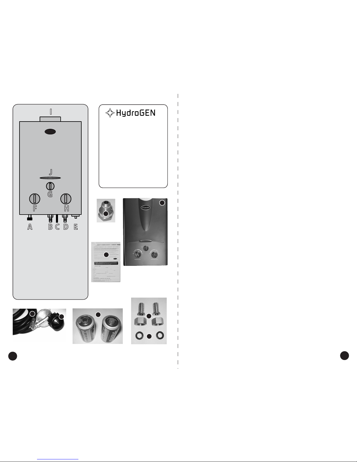
A - Gas Inlet
B - Water Outlet
C - High Water Pressure Relief
D - Water Inlet
E - Battery Compartment
F- CO2 Output Adjustment
G - High/Low Burner Setting
H - Water Cooling Adjustment
I - CO2 Exhaust
J - Flame Sight Glass
F H
G
J
I
3
• HydroGEN Unit
• (1) 12’ Propane Hose
• Propane regulator
• (2) ½” Hose
Barb Adapters
• (2) Rubber Gaskets
• (2) ‘ D’ Size Batteries
• (1)GasAdapter Fitting
• (1) Warranty Card
• HydroGEN Unit
• (1) 12’ Propane Hose
• (2) Rubber Gaskets
• (2) 2 ½” Hose
Barb Adapters
• (2) ‘ D’ Size Batteries
• (1)GasAdapter
Fitting
Packing List:
2
1
34
5
6
7
Hanging Method: The HydroGEN can be suspended
from the ceiling using chains and “S” hooks. First
securely fasten two chains 14” apart to a rafter,
brace, beam, etc (not just into the sheetrock). Keep in
mind that there is a flame inside and when we say
securely fasten we mean it. Notice there are ¼” holes
at the top center of the sides. These holes are there to
allow for installations of “S” hooks that can then be
attached to the chains at least 2’ from the ceiling or
any other obstruction.
Wall Mount Method: The HydroGEN can be screwed
into a wall brace, stud, or beam using the brackets
located at the top and bottom of the unit. Remember
2’ from the top of the HydroGEN to the ceiling or any
other obstruction.
Ducting CO2: When mounting the unit inside the
grow room, no ducting is required. If you choose to
mount your HydroGEN outside your grow room, a
3"double-wall ducting from your local hardware
store is recommended. Note that this is NOT
aluminum dryer vent, it's double-walled, insulated
steel of the same type used in hot water heater
applications. The vent piping should travel at an
upward pitch to ensure that CO2 will travel into the
grow room. When installed at an upward pitch CO2
will travel up to 5 feet. We do not recommend using
a booster fan as they can affect flame efficiency, but
a very low cfm fan can be used if forced to duct CO2
further than 5 feet from the unit. DO NOT use a fan
more powerful than 20 cfm. Also, when using the
CO2 generator outside the grow room, we
recommend mounting a carbon monoxide detector
in the room with the generator. This can be
purchased at your local discount store for about $10.
We recommend this because even though the
majority of CO2 is being ducted into the grow room,
some will still be released into the room in which
the generator is housed, and gas levels should be
monitored to ensure safety. The odds of CO levels
rising to dangerous levels is very, very slim but it's
much better to be safe than sorry.
Propane Hose: The propane hose should be in good
condition free from cracks or kinks. The hoses
fittings and regulator should also be in good
condition and should not be used if any damage has
occurred. Attach the supplied propane hose to the
HydroGEN using a properly sized wrench WITH A
BACKUP WRENCH on the unit itself. Make it snug,
but don’t break it. Over tightening can cause a gas
leak. Attach the other end of the hose to a 20 lb
propane bottle that is in good condition. Do not use
propane bottle that has a damaged, old, or leaky
valve. After installing open gas valve and check for
leaks. Applying soapy water over the joints will tell
you right away if there is a leak.
Attaching Water Hoses: Snugly screw both supplied
hose barb adapters onto the water inlet and outlet.
MAKE SURE THE RUBBER GASKET IS INSTALLED!
Attach ½” ID HEAVY DUTY REINFORCED TUBING to
the hose barbs and install hose clamps. Cold water
inlet should be clearly marked along with the hot
water outlet.
Installing Batteries: The battery compartment is
grey and is located on the bottom of the
HydroGEN. The unit is supplied with two “D” size
batteries and they must be installed properly. The
+ and – are marked on the inside of the battery
compartment.
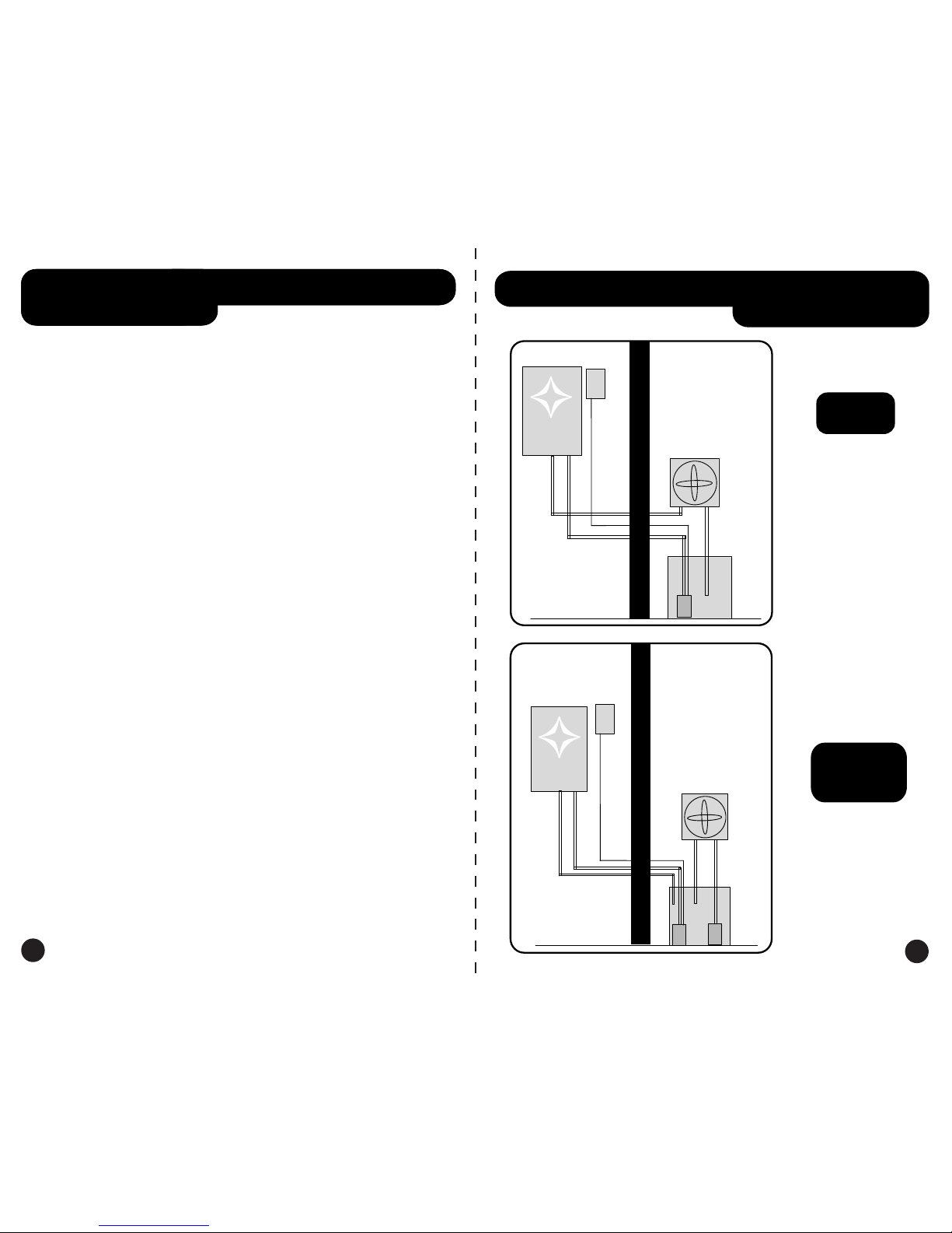
Starting Unit:
The HydroGEN's burner is activated
by 1.5 gpm of water flow and also requires at least
3 P.S.I. of pressure to operate. You must either
connect the unit to a submersible or inline pump
with at least 15' of lift that is powered on by the
co2 monitor, or the unit can be hooked directly to a
pressurized water source like a municipal water
supply. In this manner an on/off valve can be
controlled by the co2 monitor. For more water
supply ideas go to www.hydroinnovations.com. If
your water supply is ready it’s time to fire it up.
Turn on the water supply to the HydroGEN and you
should hear clicks which is the automatic ignition
lighting the burner. If the unit does not light right
away this is most likely caused by air in the
propane hose. Turn off the water
supply and then
on again , this is normal and it may take several
attempts to remove all the air from a new unit.
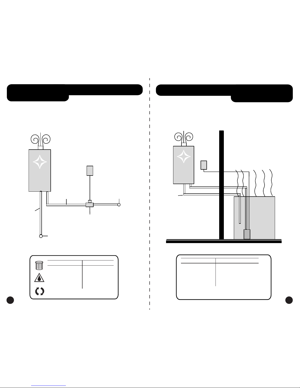
Acceptable Water Sources: Clean water of course,
used nutrient water, RO waste water, well water,
municipal water supply, swimming pool or hot
tub, collected rain water, etc. You can store your
old nutrient water and/or RO waste and run it
through the unit prior to discarding down the
drain. If using sources other than tap, we
recommend using a simple sediment filter of some
kind that can be located at any hardware store.
There is also a protective screen at the water
intake on the unit to keep large debris from
running through the unit. We recommend
checking and/or cleaning this intake screen and
your water filter (if using) at least monthly to
ensure continued adequate water flow. If water
flow diminishes, a dirty filter or clogged screen is
the most likely culprit.
Acceptable reservoirs: In-ground pools, above-
ground pools, kiddie pools, bath tubs, hydroponics
reservoirs, hot tub/jacuzzi, barrels, trash cans, or
any other water-tight container. An above-ground
pool, which can be purchased at your local
discount store for less than $100, functions as a
great reservoir when placed outside. Night air is
also a very effective cooling method.
Adjusting CO2 output and water flow valve:
There are two knobs that ultimately control the
CO2 output. At the lowest setting for both knobs
the unit generates 15 cubic feet of C02 an hour and
45 cu/ft/hr at the highest settings for both knobs.
For more cooling turn the water flow up and when
less is needed, in the winter for example, you can
turn the water flow down to retain some of the
heat. The most efficient setting for removing the
most heat is the minimum setting for the gas and
the maximum output for the water.
Installation Instructions
1
2
3
4
5
6
7
8
• (1) Warranty Card
8