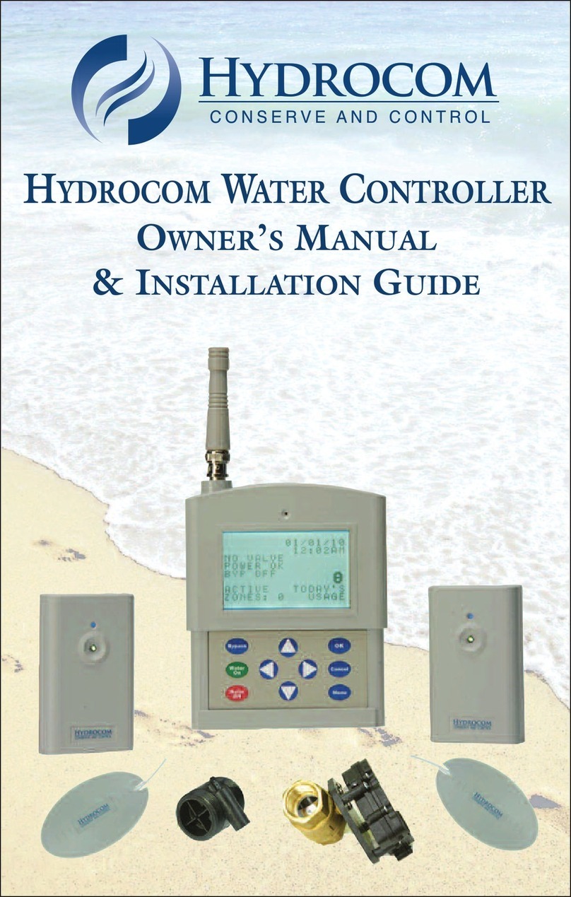
Hydrocom Water Controller II User manual


Owner’s Manual
TABLE OF CONTENTS
2Introduction
3 Product Contents
3-10 Installation
Step 1: Controller Location
Step 2: Mounting Bracket and Control Module
Step 3: Valve(s) and Flow Meter(s)
Step 4: Electrical Connections
Step 5: Alarm System Connections
Step 6: Power Supply
Step 7: Wireless Sensors
Step 8: Internet Connections
Step 9: Cover
11-13 Manual Operation
Controller
Sensors
Valves
14-15 Control Panel and Dashboard
Legend
Boxes 1-4
16-20 Controller Set up
Step 1: My Account
Step 2: Device Set Up
Step 3: Valves
Step 4: Flow Meter
Step 5: Sensors
Step 6: Alerts
21 Maintenance
21-23 Troubleshooting
24 Warranty Information
25 Regulatory
1

2
INTRODUCTION
Conservation and Control
Water: Our Scarcest Resource and the #1 Cause of Insurance Claims.
Our unique, patented-technology monitors water consumption in two ways; cumulative gallons
used, and consecutive gallons used. Using a Smartphone, tablet, or PC, real time-water usage
monitoring is now possible. This enables conservation through awareness, and helps prevent
unmonitored internal flooding of homes, offices, and businesses.
CUMULATIVE USAGE: In order to assist with water conservation, the Hydrocom system
displays daily and month-to-date usage, and additional reports are available for the week, year,
or longer. This is accomplished by collecting water usage and displaying it much like mileage on
the odometer in a car. By providing water usage data in real time, property owners are now able
to conserve water.
CONSECUTIVE USAGE: Preventing the #1 insurance claim from occurring is accomplished
by monitoring consecutive gallons used - In your home - other than taking a bath or shower, the
water should never be on continuously for more than 3-4 minutes. We have two modes that allow
you to address this problem.
HOME MODE: By tracking continuous gallons used, this mode should be set to allow normal
water usage in a home when it is occupied, allowing for baths and showers.
AWAY MODE: By tracking continuous gallons used, this mode should be set to allow for
normal water usage in a home, subtracting showers and baths since the property is unoccupied.
Please note, that it is possible for there to be slight differences between the water
report, and your actual water bill. Use of our product is not a guarantee that water
damage will not occur. The product is not a replacement for your Insurance policy.
Many insurance companies offer discounts with the installation of the product; you
are encouraged to contact your agent to see if your property qualifies.
Due to the fact that every property and installation can vary significantly, it is very
important to consult with a licensed plumber prior to installation. There are many
factors that can determine the best location for the controller, valves, and flow meters.

3
PRODUCT CONTENTS
1Motorized Ball Valve - <=.25% lead -
complies with Vermont Act 193 and California HS code 1953
1Flow Meter- .275-35 GPM flow rate, 125 max PSI,
120 degree max temperature
2Wireless Transceiver- 900 MHZ two way communication
2Sensor Probes - RoHS complaint
1Power Supply- FCC Class B UL approved
1Controller Module - NEMA 4 rated (assembled)
1Mounting Bracket (assembled)
1Controller Cover (assembled)
1Hardware Mounting Kit
INSTALLINg ThE hyDROCOm SySTEm
THE HYDROCOM SYSTEM has a number of electrical and mechanical connections that need
to be performed in order for the product to work correctly. This symbol indicates important
safety warnings.
STEP 1: SELECTING THE CONTROLLER LOCATION
Choosing where to install the controller is a very important step. The controller is typically installed
where the water supply first enters a home, such as in a basement, garage, or a mechanical room.
The controller is designed to operate via the Internet. It can also operate without an Internet
connection via a Smartphone or tablet. However, it is highly recommended to connect to the
internet one of three ways.
ETHERNET: Make sure that the router cable can reach the controller.
WI-FI: Make sure that a Wi-Fi signal is present and accessible.
CELL MODEM: Make sure that a cellular signal is available.
The plastic enclosure that houses the motor on top of the automatic water shut-off valve has a
NEMA 4 rating, meaning that it is water-resistant and splash-proof. Although the enclosure can
withstand moderate weather, it is recommended that the controller, valve(s), and flow meter(s)
be installed indoors.

4
Operating and storage temperature -20°F to 130°F.
The valve and flow meter come with 25 feet of cabling. Make sure the valve and flow meter cables
can comfortably reach the controller.
STEP 2: MOUNTING BRACKET AND CONTROLLER
Remove the plastic cover from the controller, and then separate the mounting bracket from
the internal controller module. Install the mounting bracket to the wall using three screws and
anchors (provided). After installing the mounting bracket, simply re-insert the controller module
into the four tabs located on the sides of the mounting bracket. It will snap into place. In the
event that you have the ability to hide the valve and the flow sensor wires, an access area below
the mounting bracket has been provided. Or, you can simply leave the wires exposed and enter
through the bottom of the controller. (Tie wraps are included)
CAUTION:
DO NOT TURN THE CONTROLLER ON/OFF SWITCH TO “ON” AT THIS STEP!
STEP 3: INSTALLING THE VALVE(S) AND FLOW METER(S)
The Hydrocom system comes standard with one valve and one flow meter sensor. An additional
valve and flow meter sensor can be added to the system. Typical uses include a dedicated hot
water line in a condominium or office space, an irrigation/sprinkler supply, or a guest house. This
valve and flow meter can operate independently of valve 1. We suggest that you call us to tailor
this application to your individual needs.
CAUTION: VALVE(S)
It is illegal, and in violation of all building and safety codes to install the automatic water
shut-off valve(s) in any manner such that:
By closing the automatic water shut-off valve(s) a fire sprinkler system would be
unable to work correctly.
By closing the automatic water shut-off valve(s) a fire sprinkler system
would be unable to function at its fully designed capability.
By closing the automatic water shut-off valve(s) any life safety device would be
rendered ineffective or its operation would be minimized, or compromised in any way.
Do not insert anything inside the valve(s) while it is not
connected to a water supply. Serious injury and/or valve
damage may occur.
A licensed plumber must install the automatic water
shut off valve(s) and flow meter(s).

5
CAUTION Additionally, DO NOT install the valve(s) in any manner such,
that if the valve were to close:
1. A water softener were to close would not operate correctly.
2. A sprinkler/ or irrigation system would not operate correctly.
(Unless using two valves and Valve #2 is designated for irrigation).
3. A well pump/ pressure tank would not operate correctly.
4. A recirculation pump could fail.
The ball valve(s) are bi-directional. It does not matter which end of the valve is input or output.
The valve is 1” and it is recommended to use plumbers tape when connecting the male
adapters to the valve.
OUR SYSTEM IS ALSO CAPABLE OF OPERATING LARGER VALVES AND FLOW
METERS. SEE OUR WEBSITE WWW.HYDRO-COM.COM/ FAQ INSTALLATION FOR
THE CORRECT OPERATION AND WIRING.
IF YOU ARE USING WELL WATER, OR A WATER SOURCE THAT HAS HIGH SUSPENDED
SOLIDS, WE RECOMMEND THE USE OF A 50 MICRON PRE-FILTER BEFORE THE
FLOW METER AND VALVE.
FLOW METER(S) INSTALLATION -- AUTOTROL TURBINE
Observe the flow direction arrow on the turbine. Provide
a minimum of 12 inches (306 mm) of straight pipe before
and after the 2 inch (51 mm) turbine, and 6 inches (153
mm) before and after the 1 inch (25 mm) turbine.
Be especially careful of turbine orientation (Figure
3). Both horizontal and vertical orientations are
acceptable,however, be certain that you will have a full
pipe condition at all times. DO NOT mount the turbine
in a vertical orientation in a down-flow condition. Under
normal conditions the turbine will require no maintenance.
In areas where the make-up water has suspended solids,
prefiltration is required. A Wye-type stainer with a 50 mesh
specification is recommended.
NOTE: DIMENSIONS ARE FOR REFERENCE ONLY. Care should be taken to
adequately support and align the pipes running into and out of the turbine.
CAUTION: DO NOT over tighten the turbine housing adapter nuts or you may
damage the threads. Hand tight plus 1/4-turn on nuts is recommended.
Insert sensor probe into turbine housing. The probe will “click” into place when inserted the
proper depth into the housing receptacle. Run the cable to the controller along the pipe using
cable ties or in conduit.
Figure 2 2-inch (51 mm) Turbine

6
CAUTION: DO NOT coil or twist probe cable together with power line wiring. DO
NOT attempt to pull the hall effect sensor through conduit.
TURBINE METER ASSEMBLIES
Figure 3
ITEM NO. PART NO. DESCRIPTION
1 3023536 2” NPT Turbine Assembly Complete
2 3023537 2” BSPT Turbine Assembly Complete
3 3023534 1-1/2” NPT Turbine Assembly Complete
4 3023535 1-1/2” BSPT Turbine Assembly Complete
5 1034080 2” PVC Turbine Assembly Complete
6 1034081 50mm PVC Turbine Assembly Complete
7 1033358 2” Turbine Meter Only
8 1030664 2” Turbine Nuts
9 3030498 2” Turbine Gaskets
10 3014558 2” NPT Stainless Steel Adapters
11 3014559 2” BSPT Stainless Steel Adapters
12 3014630 1-1/2” NPT Stainless Steel Adapters
13 3014632 1-1/2” BSPT Stainless Steel Adapters
14 1030666 2” PVC Solvent Weld
15 1030667 50mm PVC Solvent Weld
16 3023532 1” NPT Turbine Assembly Complete
17 3023533 1” BSPT Turbine Assembly Complete
18 1033317 1” Turbine Assembly Only
19 1034385 1” Turbine Nuts (For PVC Adapters)
20 1030541 1” Gaskets
21 3014557 1” NPT Stainless Steel Adapter
22 3013736 1” BSPT Stainless Steel Adapter
23 1034385 1” Nut (PVC)
24 3014631 1” Nut (Stainless Steel)

7
TURBINE METER SPECIFICATIONS
PREFERRED VALVE
AND FLOW METER INSTALLATION
WATER SUPPLY INTO HOME
EXISTING WATER SHUT
OFF VALVE PRESSURE
REGULATOR
UNION
FLOW METER
UNION
UNION
MOTORIZED
BALL VALVE
UNION

8
STEP 4-ELECTRICAL CONNECTIONS
CAUTION
DO NOT CONNECT OR INSTALL ANY OF THE HARDWARE COMPONENTS
TO THE CONTROLLER WHILE IT IS POWERED ON OR CONNECTED TO
THE POWER SUPPLY. PERFORM ALL ELECTRICAL CONNECTIONS TO THE
CONTROLLER PRIOR TO CONNECTING THE POWER SUPPLY AND TURNING
THE UNIT ON TO AVOID DAMAGING THE CONTROLLER.
THE HYDROCOM SYSTEM has 17 terminals on the front of the control panel.
They are numbered from the left to the right. Simply insert the stripped wire into the
terminal, and tighten the screw. (Check to make sure the wire is secure by giving
it a slight tug).
OUTPUTS: 1-6 Are Dry Contact Outputs
1 - Normally Closed 2 - Common
3 - Normally Open 4 - Normally Closed
5 - Common 6 - Normally Open
INPUTS : 7-10 Are Valve Connection Inputs
7 - Valve 1+ Positive 8 - Valve 1 - Negative
9 - Valve 2+ Positive 10 - Valve 2- Negative
INPUTS: 11-17 Are Flow Meter Connection Inputs
11- VS+ (Red Flow Meter) 12 - Unused 1
13 - Unused 14 - GND (Silver Shielded)
15 - Unused 16 - Flow Meter 2 (Black)
17 - Flow Meter 1 (Black )
When using two flow meters, splice or twist together the two red wires and insert
into Connection 11. Splice or twist together the two silver ground wires and insert
into Connection 14. Do not splice together the two black wires.
CAUTION!
DO NOT UNDER ANY CIRCUMSTANCES SEND
110/115/120/220/240 VOLT POWER INTO ANY OF THE
17 CONNECTIONS.
STEP 5: CONNECTING TO AN ALARM SYSTEM
There two ways THE HYDROCOM SYSTEM can connect with an alarm system:
1. Use controller outputs 1-6 to send a signal from the controller to an alarm system in the
event of a leak, flow exceeded, or temperature alarm. (See color chart above.)
2. Use a wireless transceiver to synch Home and Away. (SEE: STEP 5 ON PAGES 18-19)

9
STEP 6- CONNECTING THE POWER
CAUTION ONLY PERFORM THIS STEP AFTER ALL HARDWARE COMPONENTS
HAVE BEEN CONNECTED TO THE CONTROLLER!
POWER SUPPLY:
THE HYDROCOM SYSTEM uses a UL Class II Section B FCC approved power supply. Insert the
power connection plug into the bottom of the controller.
Prior to installing the cover, locate the ON/OFF switch on the right side of the controller module,
then slide the switch to ON. Wait for the LED lights to come on to indicate status.
THE HYDROCOM SYSTEM must use the power supply included with the product ONLY. The
power supply is designed specifically for this product and use of a different power supply will
adversely affect performance.
BATTERY BACKUP:
In case of power outages, two rechargeable batteries provide backup power for THE HYDROCOM
SYSTEM. The controller has sufficient power to operate for two weeks. In the event you are using
a valve that runs on its own 110 power, we recommend that you use a UPS (uninterruptable
power supply) to provide power to the valve during power outages.
CAUTION: BATTERY WARNINGS
TO AVOID RISK OF EXPLOSION, FIRE OR LEAKAGE OF TOXIC CHEMICALS, PLEASE
OBSERVE THE FOLLOWING WARNINGS: DO NOT DISPOSE OF THE PRODUCT
OR BATTERIES IN A FIRE, AS THE BATTERIES CAN EXPLODE. DO NOT OPEN OR
MUTILATE THE BATTERIES. THEY MAY CONTAIN CORROSIVE MATERIALS WHICH
CAN CAUSE DAMAGE TO EYES OR SKIN AND MAY BE TOXIC IF SWALLOWED.
STEP 7: INSTALLATION OF THE WIRELESS SENSORS
CAUTION:
SENSORS MUST BE INSTALLED INDOORS AS THEY ARE NOT WATERPROOF.
SENSORS GENERAL:
The sensors are comprised of a
transceiver and a probe.
THE HYDROCOM SYSTEM comes
with two wireless sensors, and can
be expanded to operate a total of 16.
However, since the controller uses a
flow meter as primary protection against water damage, it is not necessary to have numerous
sensors installed throughout the property. It is suggested the sensors be used in key locations
such as laundry and mechanical rooms.

10
Sensor power is provided by two AA batteries with a life expectancy of three to five years.
To install the batteries (included) open the transceiver by squeezing the front cover of the
transceiver at the 3 and 9 o’clock position to pull the cover off. Insert the batteries according to
the outline on the circuit board. These sensors detect leaks, and high and low temperature. The
sensors and controller share this information once every 30 seconds.
The sensors have a line of sight range of 600 feet. However, internal range is dictated by
numerous factors, such as metal and glass. Interference from other radio transmissions can
also negatively affect performance.
TRANSCEIVER CONNECTIONS
AND INSTALLATION
In order for sensors to work correctly, the
sensor probe needs to be screwed to the
terminal connector on the transceiver. IT
DOES NOT MATTER WHICH COLOR WIRE
is inserted into either connector. Simply insert
the stripped wire into the connection, and
tighten the screw terminal. (Check to make sure the wire is secure by giving it a
slight tug). Two drywall anchors have been provided to mount
the transceiver to the wall.
PROBE PLACEMENT
AND INSTALLATION
The probe is light weight, please use the enclosed anchors to
adhere the probe to the floor.
STEP 8: INTERNET CONNECTION
There are three options to connect the controller to the Internet. All methods utilize our SSL
256 bit encryption.
1. ETHERNET 2. WI-FI 3. CELL MODEM
If you are connecting the controller to the Internet via Ethernet, insert the Ethernet cable into
the Ethernet receptacle next to the power supply on the bottom of the controller, proceed to
Step 9. If you are not using Ethernet, proceed to Step 9, as the Wi-Fi and Cell modem require
no installation at this point.
STEP 9: INSTALL COVER
Simply take the cover and snap it onto the mounting bracket.

11
MANUAL OPERATION OF THE CONTROLLER
WATER INDICATOR: This indicator will light up blue when a valve has been installed, and
the valve is open. Upon closing the valve, the light will flash red.
FLOW INDICATOR: This indicator will light up blue when a flow limit has been exceeded.
Additionally, it will flash to indicate when the controller has been put into “Override” mode.
SENSOR INDICATOR: This indicator will light up blue when a sensor has detected a leak. It
will turn off once the leak has been resolved.
INTERNET CONNECTION: This indicator displays which method you are using to connect
to the Internet.
ONLINE: This indicator will light up green when the internet connection is active.
TEST: This button will send a test email to all users who have been entered into your alert
programming. Also, to bypass the flow meter function, press the button 5 times.
RESET: Pressing the reset button changes the WIFI mode to STA AP mode.
ON/OFF: These buttons control Valve 1 and Valve 2 independently.
VALVE
ON/OFF
CONTROLLER
RESET
TEST

12
CONTROLLER IN A NORMAL STATE
Two valves are installed and open, Wi-Fi is being used to connect to the Internet, and the
Internet connection is online.
CONTROLLER IN ALARM STATE
Two valves are closed (indicators are red), The flow indicators are blue, and the sensor
indicators are blue.
FLOW
ALARm
VALVES
CLOSED
SENSOR
ALARm

13
MANUAL OPERATION: SENSORS
TO TEST THE SENSOR CONNECTION: Press the Send button on the transceiver: two
flashes indicate that the controller accepted the signal and replied to the transceiver.
NORMAL OPERATION . . . . . . . . . . . . . . . . . One flash every six minutes.
ALARMS (Leak-Low Battery-Low Temp) . . . . . Three flashes every five seconds.
UNSUCCESSFUL TRANSMISSION . . . . . . One steady flash after two seconds
upon pressing send.
SUCCESSFUL TRANSMISSION . . . . . . . . . Two quick flashes upon pressing send.
MANUAL OPERATION: VALVE(S)
IMPORTANT: IN THE UNLIKELY EVENT THE HYDROCOM SYSTEM FAILS TO
OPEN A VALVE, THE LAST RESORT IS TO MANUALLY OPEN THE VALVE.
PRIOR tO dOIng thIs, dO the fOllOwIng:
1. Make sure the valve is enabled. Log onto the web app (www.hydrocomhome.com)
and go to System/Settings/Valves. Make sure the box(es) is checked.
2. Make sure the system has not detected a leak. Do this by either checking for alerts or
manually inspecting the sensors.
To manually open the valve, unscrew the three mounting screws from the black actuator (Figure
1) and rotate the valve 90 degrees to align with valve stem indicators (Figure 2). Reinstall the
actuator to return the valve to its original operational capacity by tightening the 3 mounting
screws. DO NOT misalign the valve with the valve stem indicators, as this will cause the valve
to not function properly.
Figure 1 Figure 2

14
CONTROL PANEL AND DASHBOARD
TIME AND DATE: This displays the last time the controller connected with the server.
REFRESH: This will update and refresh the web page.
ALERTS: If an alert is detected it will be displayed here.
MY ACCOUNT: This tab allows access to My Water usage, MY account information,
and to log out.
SETTINGS: This tab allows access to My Device, System Set up,
Alerts and Support.
The dashboard contains four boxes that allow you to easily monitor and control the system. An
info tab is provided in the lower right corner of each box.
BOX 1: FLOW MODE
This box displays the current flow mode in color on the left.
HOME: This mode is used when a property
is occupied.
AWAY: This mode is used when a
property is unoccupied.
OVERRIDE: The mode allows unlimited consecutive
water usage.
To change the flow mode, click on the mode you want to enable, the graphic will appear in
color on the left to show that the mode has been changed.

BOX 2: VALVE(S)
This box displays the status of each valve. Click the ON
or OFF button to open or close the valve. An open valve
will appear green with “OK”, and a closed valve will
appear red with “Off”.
BOX 3: WATER REPORT
This box displays water usage for the day and the
month. Additional Reports tab provides customized
reports for the day, week, month, year and longer. The
box also contains a monthly gauge for quotas and
alerts (if programmed.)
BOX 4: SENSORS
This box displays all sensors, their status and temperature.
PROGRAMMING THE CONTROLLER
ANDROID DEVICES
www.googleplay.com/apps/hydrocom
APPLE IOS DEVICES
https://itunes.apple.com/apps/hydrocom
We have developed two applications: The mobile app is available in iTunes and Google Play
and is used to control your system. The WIFI configuration app is only available from Google
and is Android compatible. If you are connecting via WIFI, you will need the WIFI connection
wizard from Google Play.
USING THE APP: Make sure you have your Unit ID and network password. The wizard will
prompt you through the steps. After you Press Finish:
1) Remove the controller cover
2) Turn the on/off button to off
3) Unplug the power supply
4) Wait a few seconds, and then re-power the unit and install the cover
5) In about two minutes you should see a solid green online LED on the controller
15

If you are connecting to the Internet via a cell modem
simply power the unit up and wait for the online LED to
turn green. Please make sure you are logged on to:
www.hydrocomhome.com
The default user name is
hydro
and your Unit ID
and the default password is Hydrocom or hydro
depending on your version. Once you have logged
in, you can change the user name and password.
STEP 1: USERNAME & PASSWORD
Click on the Person icon between the Alerts and Settings icons.
It is very important to record your user name, password, SSID, and SSID password! There is a
space on the back of this manual for that purpose, and there is a label in the hardware kit as
well. This label can be placed on the bottom of the cover or next to the controller. If you are
connecting to the Internet via cell modem, we still suggest you fill in the SSID and network
password. Click Update Profile to save.
STEP 2: DEVICE INFO
Go to the Settings tab, and select “device”. The Device ID is located here. Select the
appropriate time zone, and name the device. The device ID can also be found on the inside
of the controller. When finished, click save.
16
hydro1234
Hydrocom or hydro

17
STEP 3: FLOW METER PROGRAMMING
Go to Settings/System/Flow Meter Settings.
IMPORTANT! It is essential to understand the system monitors water usage two ways.
1) CUMULATIVE USAGE: Measures how much water is used in total, just like the odometer
in your car.
2) CONSECUTIVE USAGE: Measures how much water is used continuously. Consecutive
usage triggers the valve to shut when the programmed Consecutive amount is exceeded. The
system then resets the Consecutive gallons automatically after the water flow has stopped.
Example - The system is in the home mode and it is set to 50 consecutive gallons.
If you take a shower using less than 50 gallons the valve will not close, and the
controller will reset consecutive gallons to zero when you finish showering. If you take
a shower using 51 gallons the valve WILL close.
HOME MODE: The number of gallons entered here, is the number of gallons that can be
used consecutively prior to triggering the shut off valve. The default setting is 50.
AWAY MODE: The number of gallons entered here, is the number of gallons that can be used
consecutively prior to triggering the shut off valve. The default setting is 5.
MONTHLY USAGE: The number entered here appears on the water gauge in Box 3. The red
area on the water gauge represents 70% of this monthly number.
MULTIPLE FLOW METERS: If the system is running two flow meters, check the boxes to
enable both flow meters, and then program the Home and Away settings for both Flow Meters.
When finished, click save.

18
STEP 4: VALVE PROGRAMMING
GO TO SETTINGS/SYSTEM/VALVE SETTINGS: To add or remove a valve from the
system, click on the appropriate buttons. Also, you can perform a test on the valves by clicking
on the test buttons.
STEP 5: SENSOR PROGRAMMING
GO TO SETTINGS/SYSTEM/SENSOR SETTINGS: The controller comes with 2 sensors
enabled. By clicking the Edit button, you can name the sensors. Also a screen appears showing
the sensor serial number and name. The sensors default settings are Enabled with Leak
Detection on.
There is an option to close the valve if a sensor detects low temperature. When this option is
enabled, if an inside temperature of 40 degrees or lower is detected for over 10 minutes, this
will be communicated to the controller and the water will shut off.
To enable this option, check the box and click SAVE.
ADDING SENSORS: To add additional sensors, click on the + button on the Inactive Sensor
Menu. Click on the edit button to Enable a new sensor and follow the instructions above.
REMOVING SENSORS: Click on the edit button and uncheck box 5 - this will disable the
sensor, and it will appear in the Inactive Sensor Menu.
Table of contents
Other Hydrocom Controllers manuals
Popular Controllers manuals by other brands

Sanhua
Sanhua SEC61X SERIES Product data

Stevens
Stevens SOLO Quick start instructions

Concoa
Concoa 601 Series Installation and operation instructions

Hansen
Hansen HA4A series Specifications, Applications, Service Instructions & Parts

Linear Technology
Linear Technology LT3507 Demo Manual

Dwyer Instruments
Dwyer Instruments TSW Series quick start