Hydrological Services Pty Ltd
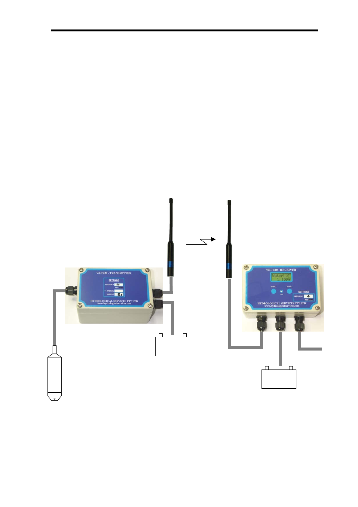
Wireless Level Transmitter
© Copyright WLT420 100-10 Issue 1.20 5 Dec, 2007
3.3 Displaying Water Volume
The WLT420 has the facility to display the water volume (of a reservoir) as a function of the
water level. See Appendix B for details on how to derive the appropriate equation and hence
the terms of the 4th order polynomial Poly0 thru to Poly4. The formula generated in the
example is :
Water Volume = 0.8065 x4- 18.957 x3+ 165.76 x2- 19.588 x + 0.000
(where x is the water depth in metres)
For this example, the polynomial terms entered into the WLT420 are as follows :
(Please note the sign of each term !!!!!)
Poly0 = 0.000 ( term for x0, which is the intercept )
Poly1 = - 19.588 ( term for x1, which is just x )
Poly2 = 165.760 ( term for x2)
Poly3 = - 18.957 ( term for x3)
Poly4 = 0.8065 ( term for x4)
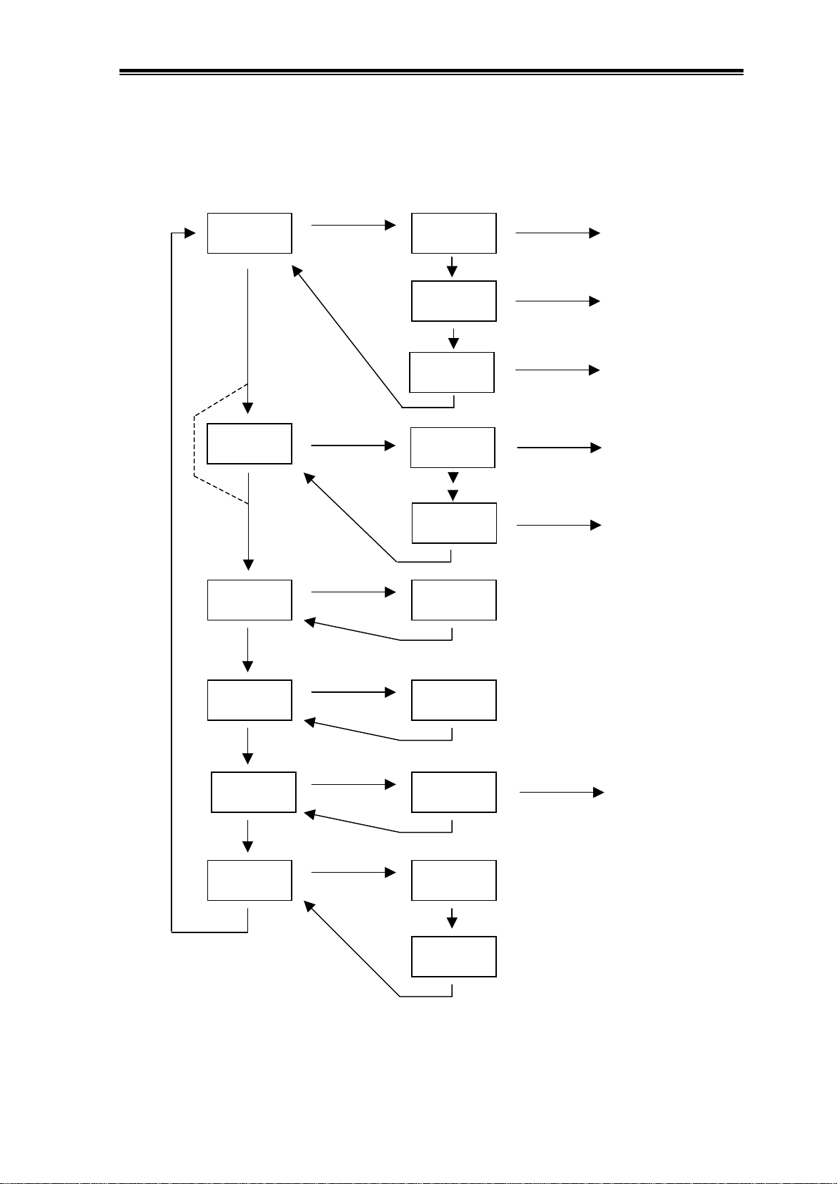
The Volume display option must first be enabled. (Examine the LCD navigation chart on the
previous page.)
• Press the Scroll button and step to the “WaterLvl” menu.
• Press and hold the Select button for 5 secs until the “SetLevel” menu appears.
• Press the Scroll button twice and advance to the “VolDsply”.
• Press the Select button to start the “Disabled” flashing.
• Press the Scroll button to select “Enabled” flashing.
• Press the Select button to stop the flashing.
• Press Scroll button to save the VolDsply enabled feature.
• Press the Scroll button to advance to the “Volume” display.
• Press and hold the Select button for 5 seconds until the “Poly0” menu appears.
• Press the Select / Scroll / Select buttons to advance each digit of Poly0.
• Press the Scroll button to step to “Poly1”
• Repeat the previous steps to set Poly1, Poly2, Poly3 and Poly4.
• Press Scroll to step back to the “Volume” display.
• The water volume should now be displayed.
By using the “Set Level” menu item, you can preset various levels and hence check the Water
Volume. As the water level now changes between 0.000m and 10.000m the water volume of
the reservoir will be displayed.
The water volume created from this 4th order polynomial is not exact – but it is a very good
approximation.