HydroQuip PLUS OZONE Guide

1
PLUS OZONE™INJECTOR KIT
CONNECTION AND ADJUSTMENT PROCEDURE
Read all instructions prior to performing work. If you do not understand these instruction or
are unable to perform the work, contact your system provider for assistance
8000 systems equipped with a factory installed Plus Ozone™come with a visible green logo on the cabinet
access door and the Plus Ozone™ generator installed into the upper cabinet. Reference Dia. #1
SAVE THESE INSTRUCTIONS
Kit includes:Tools and supplies needed:
1ea. Ozone Injector Manifold *Timer with second hand
1ea. Ozone Check Valve Kit *16oz water bottle
*Only needed for type #2 setup
NOTICE! If you choose to disconnect the Plus Ozone™ purification system, or need to electrically disarm it for any
reason, follow the “Disable Plus Ozone™ Option” provided in this instruction
ELECTRICAL CONNECTION
The Plus Ozone™generator comes pre-wired to the 8000 control system as shown in Dia #1, there are no additional
electrical connections required
Dia. #1

2
LOCATING THE OZONE INJECTOR MANIFOLD
1. The manifold must be placed at or near the operating equipment
2. Place the Ozone Injector Manifold into the return system plumbing as the last item in the equipment sequence
before the water returns to the jets or wall fitting. Reference diagram #2 for typical plumbing layout, correct
manifold location and water flow direction.
Note that your system provider may have different arrangement for pump filter and heater sequence, however this
manifold must be placed after the water has passed through all equipment
WARNING! Placing this manifold in any other location i.e. in between the filter pump or in front of the heater will
cause operational problems and equipment damage including loss of pump prime, reduced filtration, and heater
damage that is not covered under warranty.
3. The manifold must be plumbed in the correct direction for water flow. The arrow label placed on the manifold
shows the direction water must flow through the manifold for proper operation. (Label arrow should not be
pointing toward any other component in the plumbing system)
4. Connect manifold to system pipe with PVC glue. DO NOT mount manifold upside down or vertically
INSTALLING CHECK VALVE KIT WITH TUBING
Follow instructions included with the Ozone Check Valve Kit to connect supply tubing between the Ozone Injector
Manifold and cabinet mounted Plus Ozone™generator barb.
Some extended length injector manifolds (not shown) come with a bracket and bolt assembly to help support the
additional plumbing weight. When provided, install bracket and secure to the plastic base with screws as shown in
Dia.# 3
Dia #3

3

4
ADJUSTING OZONE VACUUM FLOW

5
Follow these steps to fine tune your ozone delivery and maximize the sanitation benefit from your Plus Ozone™system.
The ozone injector can only be adjusted when the vessel/tub is full of water and the pump is operating. Select your
pump and return plumbing type (#1 or #2) then follow procedures for proper adjustment
PUMP AND RETURN PLUMBING TYPE #1 Dia.# 4
1-SPEED LOW FLOW CIRCULATION PUMP WITH SINGLE
RETURN INLET FITTING (NO JETS)
1. Confirm the Check Valve Kit is installed properly
2. When the pump is operating, slightly turn the ball
valve to divert water through the ozone injector DIA #3
View the water return fitting Dia #4 and adjust the valve
handle until very small ozone bubbles are detected
coming from the return fitting
TYPE #1 TIPS
A properly adjusted valve allows only small bubbles
to project 4-5 feet from the fitting and swirl around
for a few seconds before rising to the surface.
Larger bubbles that project less than 2 feet from
the return fitting and quickly rise to the surface are
less effective for water treatment, produce unwanted
noise, and deliver an undesirable ozone gas smell.
Continue to adjust the valve until a small bubble size is visible
*When filters become dirty, the water velocity slows and ball
valve adjustment may become necessary again to obtain the
smaller bubble size

6
PUMP AND RETURN PLUMBING TYPE #2 Dia. #5
1-SPEED OR 2-SPEED HIGH FLOW PUMP WITH
MULTIPLE RETURN INLETS (JETS)
1. Adjustment must be made when pump is operating and water
is flowing (Motors with 2-speeds must be placed in low speed)
slightly turn the ball valve to divert water through the ozone
injector Dia #3
2. Disconnect ozone tubing from generator barb and place tube
end in 16oz. bottle filled with water ( Dia #5) Time how long it
takes the ozone injector to empty the water (100% vacuumed out)
Re-test and adjust ball valve until it takes between 50 and 70
seconds to empty the water bottle.
3. When adjustment is finished, remove 100% of the water from
the hose and reconnect to the Plus Ozone™ barb.
TYPE #2 TIPS
A properly adjusted valve allows approx. 0.5 Standard Cubic Foot and Hour (SCFH) of ozone gas to be delivered
(vacuumed) from the generator. The water bottle technique is an easy measurement method and excellent substitution
for SCFH measuring equipment
TROUBLE SHOOTING
Ozone is not being delivered through vacuum line when pump is on
Symptom Cure
Injector assembly plumbed backward- Correct assembly direction using instructions
Ball Valve not adjusted correctly- Reference the adjustment instructions
Kinked or flat tubing- inspect and cure
Check valve placed in wrong direction Review kit install instructions
Check valve stuck Contact system supplier
Check ball in ozone injector stuck- Unscrew cap and confirm check ball moves free (Dia. #3)
*Note that over time the filter will become dirty and ozone delivery may slow or stop due to reduced water flow. Clean
the filter first before attempting to re-adjust ball valve for improved vacuum
Ozone smell is strong
Symptom Cure
Ball Valve not set correctly Adjust Ball Valve per instructions
MAINTENANCE
Periodic checks to tubing, check valve, and proper valve adjustment

7
ABOUT PLUS OZONE OPTION
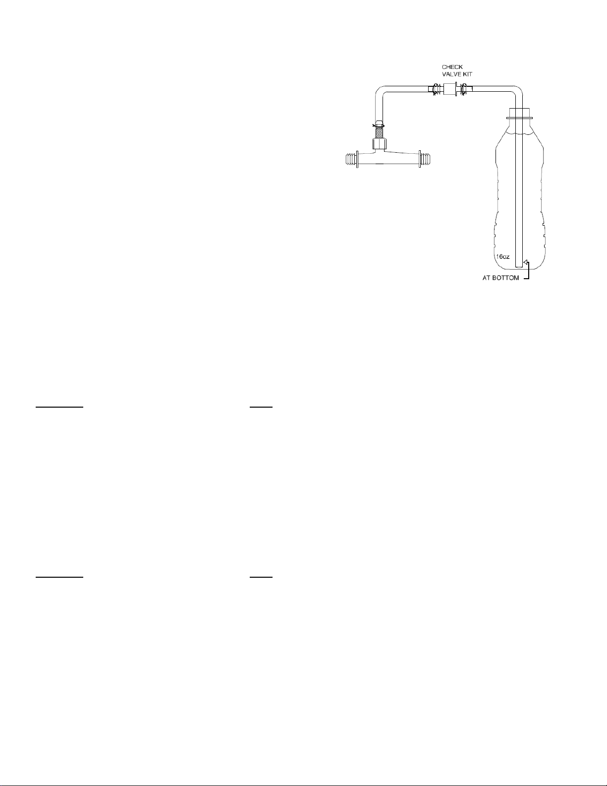
IMPORTANT! Plus Ozone™ generators operate at high voltage and must never come in contact with water at any
time. The ozone tubing kit includes a one-way check valve that must be installed correctly to prevent the backflow of
water into the ozone generator. Failure to install the valve or installing the valve backwards may cause permanent damage
and will void the product warranty.
WARNING! Ozonators exposed to water may cause system electrical problems and potential harm to the
user. DO NOT connect tubing to the ozone generator barb, unless the check valve has been installed correctly
per the instructions
DISABLE PLUS OZONE™ OPTION:
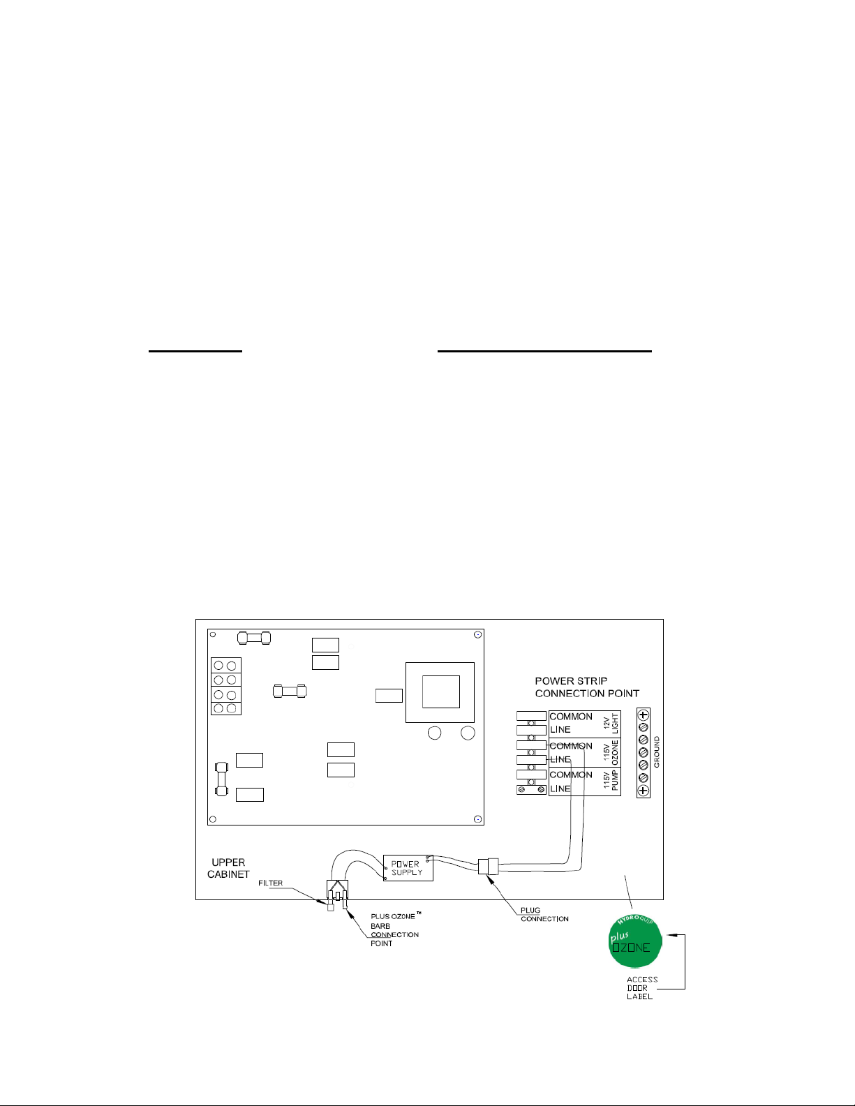
If you are unsure how to connect plumbing, or if you choose not to use the Plus Ozone™ it's important to disconnect the
electrical power. To disconnect power, simply disconnect the male and female plug connection point as shown in Dia #1,
then coil and store plugs out of the way in the cabinet.
OPERATION:
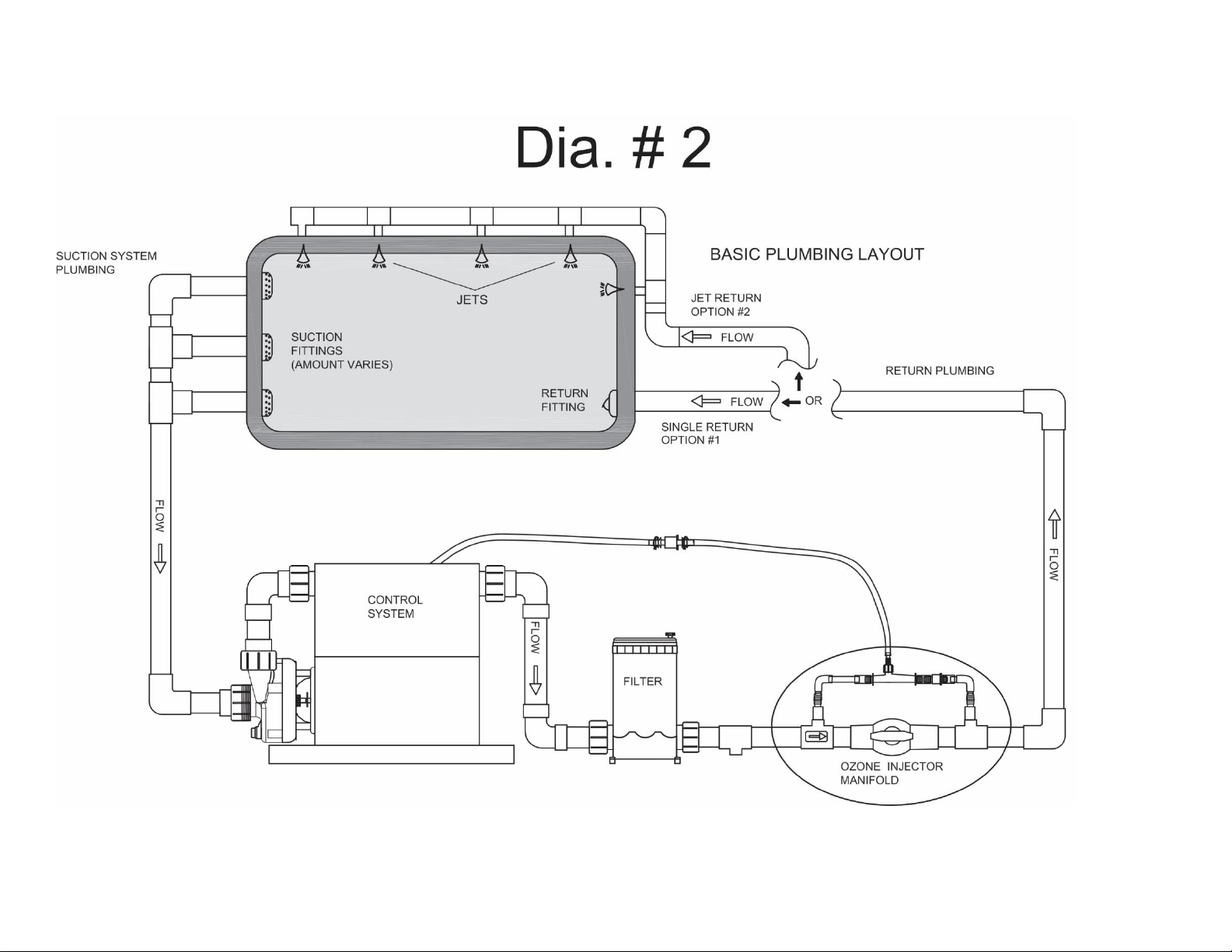
The Plus Ozone™ system is only activated when the main filter pump (pump #1) is operating in a filter cycle. Reference
“Filtration Settings” in your operation manual to adjust filter cycle duration, that will directly affect the length of time the
Plus Ozone™ operates each day.
ABOUT:
Plus Ozone™ is a Corona Discharge (CD) ozone generator that is self- operating, self-regulating and contains no serviceable
parts. DO NOT attempt to alter, adjust or repair this device. The Plus Ozone™ generator is automatically activated by
system programing, to insure it does not operate without the pump.
It is normal to encounter a purification smell at the water surface confirming ozone is being generated and delivered.
Potency has been regulated on this device, and remains non-adjustable for your safety and convenience. Ozone gas applies
an instant sanitation effect to the water, however, is does not build or maintain a lasting residual. Therefore, ozone
becomes ineffective shortly after the generator is turned off.
Ozone generated by this device is solely intended for the sanitation of water and the inner walls of the delivery piping
system by means of direct exposure, the effectiveness and expected benefit is strictly limited to the time during operation.
IMPORTANT! Consult with your tub manufacturer and/or local pool and spa professional to establish an additional
chemical regiment for water care.

8
SERVICE:
1. The Plus Ozone™ barb has a removable intake filter that must be cleaned annually. Remove the filter (ref
filter on Dia #1) and wash with clean water, allow to dry and re-install.
2. The one way check valve should be visually inspected annually to confirm water is
not getting back to the Plus Ozone™ generator.
WARNING! Disconnect tubing from the generator and electrical connection as described in
“Disable Plus Ozone™ option” immediately if found to have water present in tubing between
the check valve and ozonator. Contact your system supplier for replacement valve and tubing.
3. Plus Ozone™ CD generators have a rated life cycle of 9000 hours, after which the output of the generator is
greatly diminished and requires replacement. Calculate your annual operational hours by multiplying your
accumulated daily filter cycle time by 365. This will give you an idea when the generator will need
replacement. Contact your system provider for instructions for replacement.

9
85-0021Q Rev.02 02/12/18
Table of contents
Popular Inverter manuals by other brands

Goodwe
Goodwe SMT Series user manual

Mastervolt
Mastervolt Mass SINE 24/1000 user manual

Sunways
Sunways STT Series user manual

Valterra Products
Valterra Products Go Power! GP-SW1500TS user manual

Growatt
Growatt MIN 7000TL-XE MIN 8000TL-X Installation & operation manual

Hitachi
Hitachi J300 Series instruction manual

DASS Tech
DASS Tech DSP-338i-ODS Manual for use and installation

ROTOSOL
ROTOSOL RITxK Series user manual

Ingeteam
Ingeteam INGECON SUN STORAGE 1Play Technical guide

Lincoln Electric
Lincoln Electric MOTOVAR MV 20 Safety instruction for use and maintenance

AIMS Power
AIMS Power PWRINV400W instruction manual

Growatt
Growatt MIN 2500TL-XA Installation & operation manual