Hyperion HYP-GTW-G2 User manual

Hyperion Gateway Installaon Guide www.wrensolutions.com 7L776 Rev A 190510
INSTALLATION GUIDE
HYPERION GATEWAY
HYP-GTW-G2

Hyperion Gateway Installaon Guide www.wrensolutions.com 7L776 Rev A 190510
ABOUT THIS DOCUMENT
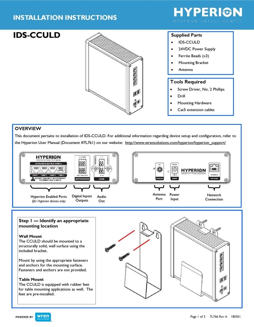
This document pertains to installation of the Hyperion Gateway (IDS-
CCULD). Before installation, please familiarize yourself with this
installation guide and review the Hyperion User Guide to understand
system configuration and setup. Supporting documentation can be
found in the Wren Support Portal at www.wrensolutions.com/support.
PRODUCT MODIFICATIONS
This product is to be installed and used for the specific purpose for
which it was designed. It is not to be modified or serviced by anyone
other then Wren. Unauthorized changes or modifications to the
product will result in the warranty being voided and could possibly
invalidate regulatory certifications.
WARRANTY
Unless otherwise noted, all products are covered by Wren's Standard
Limited Manufacturer's Warranty as set forth in the current version of
Wren's Terms and Conditions
INTELLECTUAL PROPERTY RIGHTS
Wren maintains certain intellectual property rights that may pertain to
this product. To see a list of our patents, please refer to our
TRADEMARK ACKNOWLEDGMENTS
Wren®. the Wren logo, Hyperion® and the Hyperion logo are
trademarks of Wren. The trademarks that are followed by ® are
registered trademarks in the U.S. All other trademarks and/or
registered trademarks mentioned herein are properties of their
respective owners and are for reference purposes only. The use of
such third party trademarks does not indicate any affiliation with or
sponsorship of or by Wren. All rights reserved.
NOTICES
RF Exposure for FCC
WARNING: To satisfy FCC RF exposure requirements for mobile
transmitting devices, a separation distance of 31 cm or more should be
maintained between the antenna of this device and persons during
device operation. To ensure compliance, operations at closer than this
distance is not recommended. The antenna used for this transmitter
must not be co-located in conjunction with any other antenna or
transmitter.
RF Exposure for IC
WARNING: To satisfy IC RF exposure requirements for mobile
transmitting devices, a separation distance of 44 cm or more should be
maintained between the antenna of this device and persons during
device operation. To ensure compliance, operations at closer than this
distance is not recommended. The antenna used for this transmitter
must not be co-located in conjunction with any other antenna or
transmitter.
AVERTISSEMENT: Pour satisfaire IC RF exigences d’exposition pour
les appareils mobiles de transmission, une distance de séparation de 44
cm ou plus doit être maintenue entre l’antenne de cet appareil et des
personnes pendant le fonctionnement de l’appareil. Pour assurer la
conformité, les opérations au plus près que cette distance ne sont pas
recommandés. L’antenne utilisée pour cet émetteur ne doit pas être
situé en conjonction avec une autre antenne ou émetteur.
(800) 881-2249
EXTENSION 4
PRODUCT SUPPORT
For comprehensive product support including manuals, FAQs and
troubleshooting, visit our customer support portal
WWW.WRENSOLUTIONS.COM/SUPPORT

Hyperion Gateway Installaon Guide www.wrensolutions.com 7L776 Rev A 190510
Prior to installation, verify that all hardware is included. If there are missing components, please contact Wren.
COMPONENT LIST
Hyperion Gateway 24VDC Power Supply Mounting Bracket Antenna (x2)
REQUIRED TOOLS AND ACCESSORIES
#2 Phillips screwdriver Drill Cables (CAT5 or higher)
DEVICE OVERVIEW
1. SD Card Slot
2. Hyperion Device Ports
3. Digital Input/Output
4. Audio Out
2 3 4 5 6 7 8 9 10
1
NOTE: CABLING SHOULD MEET THE T-568A WIRING STANDARD AND ALL CABLES SHOULD BE TESTED BEFORE USE.
IMPROPER CABLING COULD DAMAGE THE GATEWAY AND VOID PRODUCT WARRANTY
5. Hyperion Radio Antenna
6. Audio Channel Volume Control
7. DC Power Input
8. Network Connection
9. USB Potts
10. Wi-Fi Antenna
Hardware
24VDC

Hyperion Gateway Installaon Guide www.wrensolutions.com 7L776 Rev A 190510
BEFORE BEGINNING INSTALLATION, PLEASE
MAKE SURE OF THE FOLLOWING:
• YOU HAVE READ THE INSTALLATION GUIDE
• YOU HAVE READ THE USER GUIDE
• YOU ARE ONLY USING THE HYPERION POWER SUPPLY
• YOU HAVE TESTED AND CERTIFIED ALL CABLE CONNECTIONS
FOR PROPER PINOUT ALIGNMENT PER T-568A STANDARD
IMPROPER CABLING COULD DAMAGE THE
GATEWAY AND VOID PRODUCT WARRANTY

Hyperion Gateway Installaon Guide www.wrensolutions.com 7L776 Rev A 190510
IDENTIFY AN APPROPRIATE MOUNTING LOCATION
1
Table Mount
The Gateway is equipped with rubber feet pre-installed
for table mounting applications. If table mounting, the
wall bracket will not be needed.
Wall Mount
The Gateway should be mounted to a structurally solid
wall surface using the included bracket. Mount by using
the appropriate fasteners and anchors for the mounting
surface. (Fasteners and anchors are not provided).
3 CONNECT ETHERNET
NOTE: NETWORK CONNECTIVITY IS REQUIRED FOR
CUSTOM CONFIGURATION, BUT NOT REQUIRED FOR THE
GATEWAY TO OPERATE.
Connect the Ethernet cable to the
provided Ethernet network socket as
depicted to the right.
4 CONNECT HYPERION DEVICES
Before connecting cables from devices, refer to the Gateway Configuration Plan to ensure Hyperion devices are
plugged into their respective ports.
For Gateways that were not factory-configured, please complete the Gateway Configuration Plan before making any
connections.
NOTE:
• THESE ARE NOT ETHERNET PORTS
• ENSURE THAT ALL CABLING CONNECTIONS HAVE BEEN CERTIFIED BEFORE
ATTACHING TO THE GATEWAY
• IMPROPER CABLING COULD DAMAGE THE GATEWAY AND VOID PRODUCT
WARRANTY
• CABLES RUNS HOULD NOT EXCEED 300 FEET
2
NOTE:
• THE LONGER ANTENNA CONNECTS TO THE
“HYPERION” JACK
• FOR BEST RESULTS, THE ANTENNA SHOULD BE POINTED
AS VERTICALLY AS POSSIBLE
CONNECT ANTENNAS
Hand-tighten the appropriate
antenna to the corresponding
jack until snug.
Do not over-tighten.

Hyperion Gateway Installaon Guide www.wrensolutions.com 7L776 Rev A 190510
CONNECT DIGITAL INPUT AND OUTPUT RELAY
5
6 CONNECT AUDIO
Digital Input
The Digital Input can be used for connecting external devices to the Gateway. It
is activated when a ground signal is sensed.
Output Relay
For connecting external devices, such as LEDs or sirens.
• It can be wired as Normally Open or Normally Closed
• The Relay is rated for 250VAC/100VDC, 10 amps
The gateway supports two, independent audio channels, each with separate
connection ports and volume adjustment.
Attach speaker wires to the Gateway, making sure to note polarity.
To adjust volume, use a Philips screwdriver and turn the potentiometer
accordingly. Volume can also be adjusted via the gateway software. More
information can be found in the Gateway User Guide.
NOTE: WERECOMMEND USING 18 AWG WIRE OR LARGER AND AMAXIMUM
RUN OF 500 FEET IN ORDER TO MAINTAIN AUDIO VOLUME AND CLARITY
NOTE: DONOT APPLY ANY VOLTAGE TO THE DIGITAL INPUT OR DAMAGE WILL
OCCUR TO THE DEVICE, WHICH IS NOT COVERED UNDER WARRANTY
7 CONNECT POWER
Connect 24VDC from the supplied
power supply to the power jack.
Power can be confirmed by observing
the green power light next to the
power jack.
NOTE: ONLY USE THE SUPPLIED 24VDC POWER SUPPLY
OR IMPROPER POWER MAY BE APPLIED TO THE GATEWAY
WHICH COULD NEGATIVELY AFFECT PERFORMANCE.
REFER TO GATEWAY CONFIGURATION
PLAN FOR SYSTEM TESTING
8 SYSTEM TEST
Table of contents
Other Hyperion Gateway manuals
Popular Gateway manuals by other brands

Soma Networks
Soma Networks SOMAport 400 user guide

hilscher
hilscher NIOT-E-TIB100-GB-RE user manual

CTI Products
CTI Products RadioPro installation guide

Digi
Digi ConnectPort X4 quick start guide

SMC Networks
SMC Networks EZ Connect Commercial Cable Modem Gateway... Technical specifications

Coolmay
Coolmay BG200 user manual