CTI Products RadioPro User manual

CTI Products
RadioPro™ IP Gateway
Installation Guide
Document # S2-61781-807
For Version 8 Software
A newer version of this document may be available. Please check the accompanying CD or
www.ctiproducts.com

RadioPro IP Gateway Installation and Configuration Guide
ContactUs
Support, replacement part ordering, and service may be arranged by contacting our Cincinnati office. Parts for service
can be returned following a request of a Return Material Authorization.
CTI Products, Inc.
1211 W Sharon Rd
Cincinnati, OH 45240
513-595-5900
Disclaimer
Information in this document is provided with best efforts for completeness and accuracy. However, no guarantee is
expressed or implied, and details may change without notice.
Fontsusedinthisdocument:
Technical terms
Cross-references within this document
Hyperlinks to other documents or web pages
Warnings
Software menus, menu options, folders, pages, and parameters
Software parameter values

RadioPro IP Gateway Installation and Configuration Guide
3
Contents
1 OVERVIEW ............................................................................................................................................................................... 5
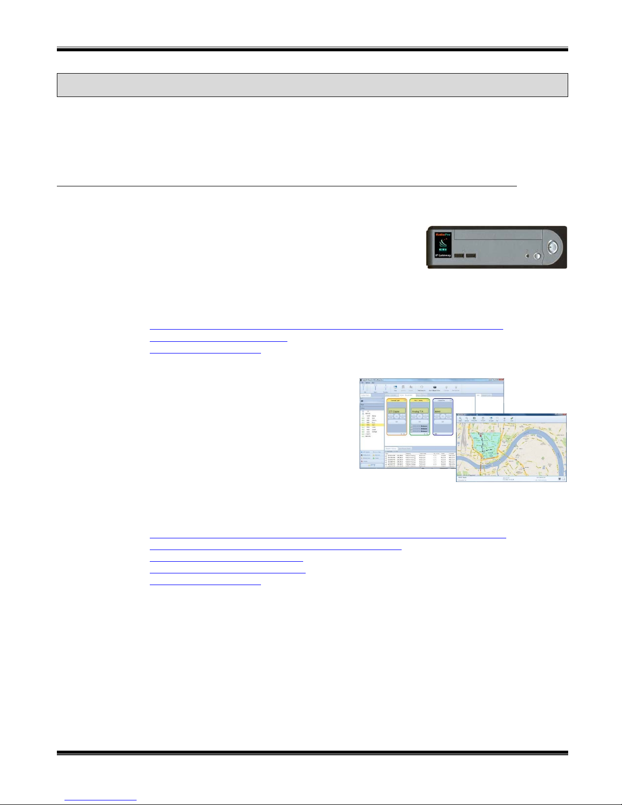
1.1 System Components ......................................................................................................................................................... 5
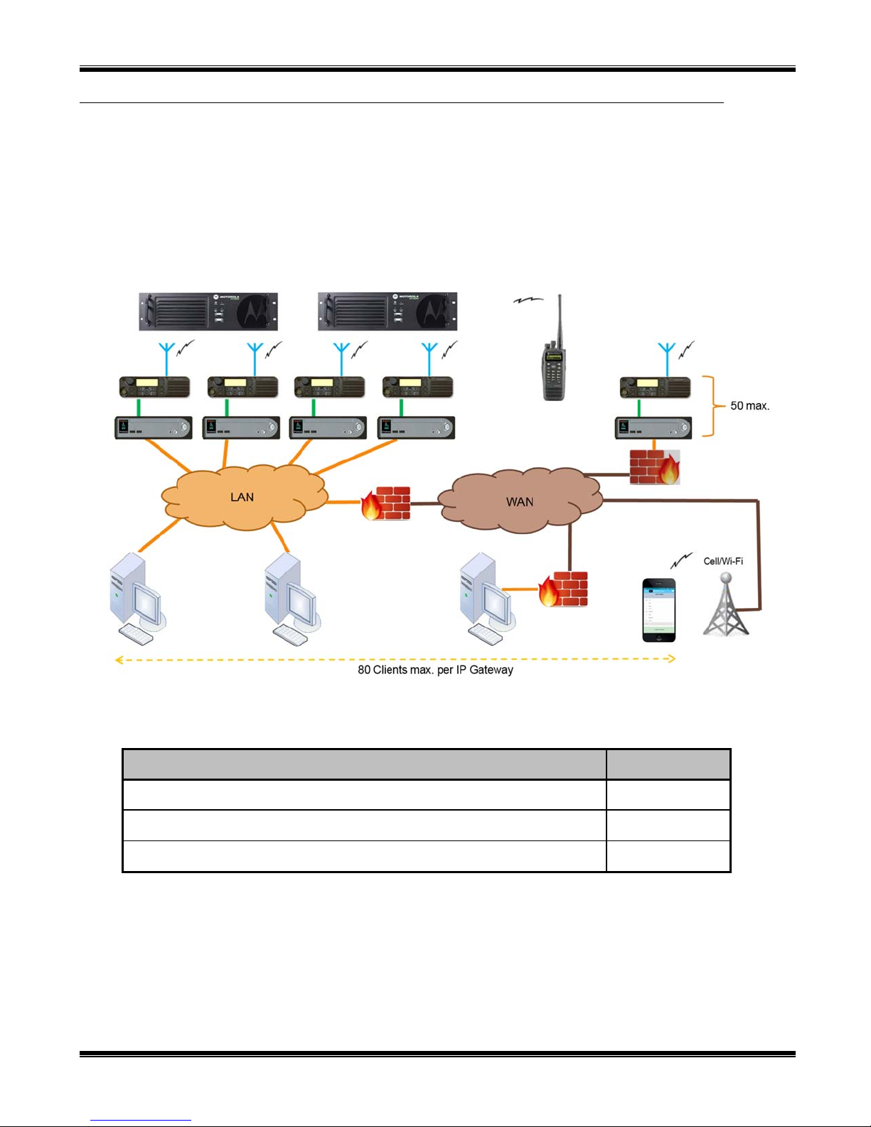
1.2 Architecture ...................................................................................................................................................................... 7
1.2.1 System Maximum Build-out ..................................................................................................................................... 7
1.2.2 System Planner Document and Template .................................................................................................................. 7
1.3 Environmental Considerations ......................................................................................................................................... 8
1.3.1 RF Interference .......................................................................................................................................................... 8
1.3.2 Lightning and Fire Protection .................................................................................................................................... 8
1.3.3 Power Requirements .................................................................................................................................................. 8
1.4 RadioPro Version Match .................................................................................................................................................. 8
1.5 Static IP Address .............................................................................................................................................................. 9
1.6 Accessing the RadioPro IP Gateway using Port Forwarding ........................................................................................... 9
1.7 Licensing .......................................................................................................................................................................... 9
1.7.1 RadioPro Dispatch Clients ........................................................................................................................................ 9
1.7.2 RadioPro Talk and Solo Clients for PC, and RadioPro Talk for Mobile Apps ......................................................... 9
2. WHAT IS INCLUDED ............................................................................................................................................................... 10
2.1 RadioPro IP Gateway Kit ............................................................................................................................................... 10
3. OTHER ITEMS NEEDED .......................................................................................................................................................... 11
3.1 Radio Interface Cable ..................................................................................................................................................... 11
3.2 Control Station Radio ..................................................................................................................................................... 11
3.3 Radio Programming Cable ............................................................................................................................................. 11
3.4 Radio Programming Software ........................................................................................................................................ 11
3.5 Laptop or PC .................................................................................................................................................................. 11
4. CONFIGURATION AND INSTALLATION STEPS OUTLINE .......................................................................................................... 12
Step 1a. for MOTOTRBO Configure Control Station Radio(s) using MOTOTRBO CPS .................................................. 1 3
Step 1c. for MOTOTRBO Configure MOTOTRBO Connect Plus Option Board ............................................................... 21
Step 1d. for MOTOTRBO Configure Subscriber Radios for ARS, GPS, and TMS ............................................................ 22
Step 1e. for MOTOTRBO Configure Motorola Repeaters for Enhanced GPS Option ........................................................ 25
Step 1a. for NEXEDGE Configure the Voice Control Station Radio(s) using Kenwood FPU ............................................ 26
Step 1b. for NEXEDGE Configure the Data Revert Control Station Radio(s) using Kenwood FPU .................................. 33
Step 1d. for NEXEDGE Configure Subscriber Radios using the Kenwood FPU Software ................................................. 34
Step 2. for MOTOTRBO Connect RadioPro IP Gateway to Control Station Radio ............................................................ 40
Step 2. for NEXEDGE Connect RadioPro IP Gateway to Control Station Radio ................................................................ 41
Step 2. for Generic Radios using Basic RxTx Connect RadioPro IP Gateway to Control Station Radio ............................ 42
Step 3. Configure RadioPro IP Gateway .............................................................................................................................. 43
Step 4. Connect RadioPro IP Gateway to IP Network ......................................................................................................... 50
Step 5. Configure Port Forwarding on Firewall Device ....................................................................................................... 51
Step 6. Install and Configure RadioPro Clients/Apps .......................................................................................................... 52
5. RADIOPRO IP GATEWAY OPERATION .................................................................................................................................... 53
5.1 Power-up ........................................................................................................................................................................ 53
5.2 Indicators ........................................................................................................................................................................ 53

RadioPro IP Gateway Installation and Configuration Guide
4
6. APPENDIX .............................................................................................................................................................................. 54
6.1 Appendix - RadioPro IP Gateway Specifications ........................................................................................................... 54
6.1.1 Mechanical and Environmental ............................................................................................................................... 54
6.1.2 Electrical .................................................................................................................................................................. 54
6.1.3 Miscellaneous .......................................................................................................................................................... 54
6.2 Appendix - IP Addressing .............................................................................................................................................. 54
6.3 Appendix - Rack Mounting ............................................................................................................................................ 55
6.3.1 Rack Shelf ............................................................................................................................................................... 55
6.4 Appendix – System Compatibility Considerations ......................................................................................................... 55
6.5 Appendix – Installing a Time Server .............................................................................................................................. 56
6.6 Appendix – Radio Interface Cables – MOTOTRBO XPR5550 ..................................................................................... 58
Motorola MOTOTRBO XPR4550/5550 Voice Radio ..................................................................................................... 58
Motorola MOTOTRBO XPR4550/5550 Data Radio ....................................................................................................... 58
6.7 Appendix – Radio Interface Cables – NEXEDGE NX700/800 ..................................................................................... 59
Kenwood NEXEDGE NX-700/800 Voice Radio ............................................................................................................. 59
Kenwood NEXEDGE NX-700/800 Data Radio ............................................................................................................... 59
6.8 Appendix – Radio Interface Cables – NEXEDGE NX720/820 ..................................................................................... 60
Kenwood NEXEDGE NX-720/820 Voice Radio ............................................................................................................. 60
Kenwood NEXEDGE NX-720/820 Data Radio ............................................................................................................... 60
Additional modifications to internal Tx-Rx unit of NX-720/820 ..................................................................................... 60
6.9 Appendix – Radio Interface Cables – Generic Rx/Tx .................................................................................................... 61
Basic Rx/Tx ...................................................................................................................................................................... 61
6.7 Appendix - Converting a Timed-license to a Non-expiring License .............................................................................. 62
7. INDEX .................................................................................................................................................................................... 63
8. SYSTEM PLANNER TEMPLATEPAGE 1 OF 2 ........................................................................................................................ 65
RadioPro IP Gateways ...................................................................................................................................................... 65
SYSTEM PLANNER TEMPLATEPAGE 2 OF 2 ........................................................................................................................... 66
RadioPro Dispatch Clients ............................................................................................................................................... 66
RadioPro Solo, Talk, and Mobile Clients ......................................................................................................................... 66

RadioPro IP Gateway Installation and Configuration Guide
5
1
O
VERVIEW
RadioPro™ provides remote access to 2-way radios via IP Networks. This “Dispatch over IP” (DoIP) solution consists
of PC-based software allowing voice and data communications between PC users and 2-way radio subscribers.
Communications with radio subscribers is also possible for remote mobile users using Android or iOS devices. A
RadioPro system consists of at least one RadioPro IP Gateway (server) and at least one client (Dispatch™, Solo™,
Talk™, or Talk for Mobile™) with an IP network connecting the RadioPro components.
1.1 System Components
CTI’s Dispatch over IP system is based on Server-Client architecture. System components are described below:
RadioPro IP Gateway Kit (CTI Part # S2-61815) is the hardware
interface that connects a mobile radio (control station) to an IP
network. The IP Gateway is the Server for the control station radio
connected to it. Each control station radio used for voice requires one
IP Gateway. System components, such as IP Gateways and clients, may be located together or separated
geographically and connected via a Wide Area Network (WAN) or Virtual Private Network (VPN). Each
IP Gateway requires a static IP address. Each IP Gateway includes a cable to connect it to the Control
Station radio. For more information, see the following documents:
RadioPro IP Gateway - Installation and Configuration Manual, Document # S2-61781
RadioPro IP Gateway Data Sheet
RadioPro System Brochure
RadioPro Dispatch Client (CTI Part #s S1-61770
Core, S1-61771 Voice Module, S1-61772 GPS
Module, S1-61773 Telemetry Module, S1-61774
Text Messaging Module) is a dispatch console for
PCs that provides voice dispatching to multiple
simultaneous radio channels or talk groups, as well as
GPS/AVL, Telemetry, Text Messaging, and Voice
Logging. Windows 8 Pro or Windows 7 Pro
operating system is required. This application can be
used with either Motorola MOTOTRBO or Kenwood
NEXEDGE systems. System components, such as Dispatch clients and IP Gateways, may be located
together or separated geographically and connected via a Wide Area Network (WAN) or Virtual Private
Network (VPN). For more information, see the following information:
RadioPro Dispatch Client Installation and Configuration Guide, Document # S2-61785
RadioPro Dispatch Client User Guide, Document # S2-61786
RadioPro Dispatch Client Data Sheet
RadioPro System Accessories Catalog
RadioPro System Brochure

RadioPro IP Gateway Installation and Configuration Guide
6
Talk™ for Windows PC is a software application for PCs and laptops that provides
voice dispatching to a single radio channel or talk group. Other features include Voice
Logging for 24 hours, Text Messaging, and channel steering. Windows 8 or Windows 7
operating system is required. This application can be used with either Motorola
MOTOTRBO or Kenwood NEXEDGE systems. System components, such as Talk
Clients and IP Gateways, may be located together or separated geographically and
connected via a Wide Area Network (WAN) or Virtual Private Network (VPN). For
more information, see the following documents:
RadioPro Talk for PC Data Sheet
RadioPro System Brochure
Solo™ Client is the legacy software application for PCs that provides voice dispatching to a single radio
channel or talk group. It requires Windows 10, 8, 7, or XP operating system. The virtual radio head
duplicates the full functionality of a XPR4550/5550 control
station, including channel steering. Other features include
Texting and Voice Logging for 24 hours. For more
information, see the following documents:
TurboVUi Solo Installation Guide, Document # S2-
61568
TurboVUi Solo User Guide, Document # S2-61432
RadioPro Solo Data Sheet
RadioPro System Brochure
Talk™ for mobile devices is a mobile app for Android™ and iPhone™/iPad™ that
provides remote access to a 2-way radio system for voice communications. This
application can be used with either Motorola MOTOTRBO or Kenwood NEXEDGE
systems. The Mobile app is useful over cellular or Wi-Fi networks when you are on-the-
go and outside the coverage of your radio system, yet still need radio communications. For
more information, see the following documents:
RadioPro Talk for Mobile Devices How-to-Guide
RadioPro Talk for Mobile Devices Data Sheet
RadioPro System Brochure
Control Station Radio - A control station radio must be used as the interface to the radio system, and
connects to a RadioPro IP Gateway using the rear accessory/communications port. Each control station
radio used for voice requires one IP Gateway. Radio models that can be used for a Control Station radio
and provide full radio functionality from a RadioPro client include:
Kenwood NEXEDGE: NX-700/800
NX-720/820 (see notes on Page 60)
Motorola MOTOTRBO: XPR5550/5580 (North America)
DGM5500/8500 (Latin America)
DM4600/4601 (Europe)
XiR M8260/M8268/M8660/M8668 (Asia Pacific)
Other radio models may be used with limited functionality by using the “Basic RxTx” configuration. This
simple interface provides only talk and listen.
Personal Computer or Workstation is required to host the RadioPro Dispatch, Solo, or Talk client.
Console accessories may include microphone and speakers (or headset), Push-to-Talk footswitch, and
touch screen monitor.

RadioPro IP Gateway Installation and Configuration Guide
7
1.2 Architecture
The IP Gateways interface the radio system to an IP network. One IP Gateway is required for each control station radio
used for voice. The IP Gateways and control station radios can be centrally located or scattered among different
locations using a Virtual Private Network (VPN) or Wide Area Network (WAN) such as the Internet.
Each IP Gateway in a RadioPro system acts as the server for the Control Station Radio connected to it, and ensures easy
wide-area deployment. Since there is not a server PC, the architecture reduces “single point-of-failure” concerns.
A system may have a mixture of RadioPro Dispatch, Solo, and Talk Clients, as well as RadioPro Talk for Mobile apps
running on mobile devices. These Clients may be centrally located or scattered among different locations using a
Virtual Private Network (VPN) or Wide Area Network (WAN) such as the Internet.
1.2.1 System Maximum Build-out
A RadioPro system may have maximum components listed below.
System Component Maximum
Dispatch™ Clients 20
Simultaneous Solo, Talk, and Talk for Mobile client connections per IP Gateway 80
IP Gateways 50
1.2.2 System Planner Document and Template
The System Planner (Document # S2-61645) includes examples for various radio network topologies, and should be
consulted if the RadioPro Dispatch client is being deployed.
Use the 8. System Planner Template Page 1 of 2 (located at the end of this document) in the planning phase of a
project to record IP addresses, usernames, passwords, serial numbers, and device names.

RadioPro IP Gateway Installation and Configuration Guide
8
1.3 Environmental Considerations
The operating environment for the IP Gateway must be within limits noted in the specifications, as well as other
conditions. Do not install equipment in an area where any of the following exist:
Extreme temperature and humidity beyond limits listed in the specifications
High EMI (Electro-Magnetic Interference) or RFI (Radio Frequency Interference)
High dust concentration
High ESD (Electrostatic Discharge)
Extreme Vibration
1.3.1 RF Interference
To prevent RF interference, Mobile radio antennas should be kept a minimum of 24 feet from the RadioPro IP
Gateway when in high-power mode, or a minimum of 12 feet when in low-power mode. Portable radios should be
kept a minimum of 6 feet from the RadioPro IP Gateway.
1.3.2 Lightning and Fire Protection
Lightning protection should be implemented at both the equipment and at the point of entry of the building. Lightning
protection and power transient protection should be implemented to reduce the risk of fire caused by these phenomena.
Circuit breakers and fuses offer the best methods for preventing extended over-current and over-voltage conditions.
1.3.3 Power Requirements
When using the supplied AC power adapter, each IP Gateway requires 100-240VAC, 200mA maximum.
When connecting a DC supply directly to the IP Gateway, each IP Gateway requires the following input, depending on
the IP Gateway Serial Number:
IP Gateway Serial Numbers Voltage Range
1000 through 3153 11.5 – 12.5 VDC
3154 and higher 12.0 – 32.0 VDC
1.4 RadioPro Version Match
RadioPro Dispatch clients and IP Gateways must have compatible versions in order to communicate with each other.
Compatibility can be ensured when the first two digits of the version match. (The third digit indicates a minor revision,
and does not need to match.) See section 6.4 Appendix – System Compatibility Considerations on page 55 for more
details.

RadioPro IP Gateway Installation and Configuration Guide
9
1.5 Static IP Address
Each RadioPro IP Gateway requires a static IP address. The IP Gateway must have IP Network Parameters
configured using ICU.exe (IP Configuration Utility) before connecting to an active network. Contact the IT
administrator in order to provide a static IP Address for each RadioPro IP Gateway, along with its Subnet Mask and
Default Gateway.
1.6 Accessing the RadioPro IP Gateway using Port Forwarding
If RadioPro clients (such as Dispatch, Solo, Talk, or Talk for Mobile) will access an IP Gateway from a different IP
network, then the IT Administrator must configure port forwarding within the firewall or router(s) that separates the
RadioPro IP Gateway from the clients. This is also true when one or more of the clients listed above will connect to a
RadioPro IP Gateway from the Internet. See Step 5. Configure Port Forwarding on Firewall Device on Page 51 for
more information.
1.7 Licensing
1.7.1 RadioPro Dispatch Clients
Each PC that runs the RadioPro Dispatch client requires a unique software license file to be imported during installation
of the software. The license file specifies the number of IP Gateways that a RadioPro Dispatch console can connect to,
as well as licensing for GPS and Text Messaging options. Connections for additional IP Gateways can be purchased
and added to the license file at any time.
1.7.2 RadioPro Talk and Solo Clients for PC, and RadioPro Talk for Mobile Apps
For client types other than RadioPro Dispatch, a license file is factory-installed on the IP Gateway, and allows Client
Connections from Talk and Solo clients (for PCs and Notebooks) and Talk for Mobile apps (for Android™ and
iPhone™/iPad™). Client Connections can be purchased when the IP Gateway is purchased, and can easily be added to
an IP Gateway that is already installed. The number of Client Connections on the license file is the maximum number
of simultaneous users of Talk, Solo, and Talk for Mobile Devices.
The number of Client Connections installed on the license file is indicated on the serial number label located on the
bottom of the IP Gateway. It can also be determined using the ICU.exe utility. See Step 3. Configure RadioPro IP
Gateway on Page 43 for more details.

RadioPro IP Gateway Installation and Configuration Guide
10
2. WHAT IS INCLUDED
2.1 RadioPro IP Gateway Kit
The RadioPro IP Gateway (Part # S2-61815) includes the following items:
CTI Part # Description Notes
S2-61815 RadioPro IP Gateway Includes power supply
S2-61782 RadioPro Installation Steps (document) Read me first
S2-61790 CD, RadioPro IP Gateway Contains Installation Guide, ICU.exe (for
configuring IP Gateway), and Solo and Talk
89-10712 Cable, Cat 5 RJ45, 10 ft Can be used to connect IP Gateway to LAN
Note:ICU.exe(IPConfigurationUtility)isavailableoneitherofthefollowingdistributionCDs:
RadioPro IP Gateway Part Number S2-61790. This CD contains an executable file that must be copied
to a writeable disk before running. (The ICU cannot be run directly from the CD.)
RadioPro Dispatch Part Number S2-61791. This CD contains an installer program that will install the
RadioPro Dispatch Client Software and the ICU onto the PC. Following the installation from the
distribution CD, this utility can be located by clicking the Start menu button, then click on All
Programs, then click on the RadioPro Dispatch folder, then click RadioPro ICU.

RadioPro IP Gateway Installation and Configuration Guide
11
3. OTHER ITEMS NEEDED
3.1 Radio Interface Cable
A radio interface cable must be ordered for each IP Gateway from the following table:
Control Station Radio Cable Part #
Motorola XPR4550/5550, DGM5500/8500, DM4000, XiR M8260 S2-61431
Kenwood NEXEDGE NX-700/800 S2-61769
Kenwood NEXEDGE NX-720/820 S2-61890
Generic radio using Basic RxTx Interface 89-12109
Other cables are available to connect a dedicated data revert cable. Contact CTI for more information.
3.2 Control Station Radio
Each Control Station radio used for voice requires one IP Gateway.
The control station radio connected to the IP Gateway must at least have the minimum firmware version listed
below.
Control Station Radio Minimum Version
Motorola MOTOTRBO in Conventional, IPSC, Cap+, or LCP 1.08.0
Motorola MOTOTRBO in Connect Plus mode 2.2.0
Motorola MOTOTRBO Connect Plus Option Board 1.3.0
Kenwood NEXEDGE NX-700/800 or NX-720/820 3.21.00
3.3 Radio Programming Cable
A radio programming cable is required to configure the Control Station radio.
Note: A programming cable connected to the front microphone connector on the Control Station radio may prevent
communications to a RadioPro IP Gateway from the Rear Accessory Connector. Therefore, when a cable is
connected to the Rear Accessory Connector to connect a RadioPro IP Gateway or a PC (during programming),
ensure that the programming cable has been disconnected from the front microphone connector.
3.4 Radio Programming Software
Motorola’s CPS (Customer Programming Software) utility or Kenwood’s KPG-111DN FPU (Field Programming Unit
software) is required to configure the Control Station radios radio for various RadioPro functions.
3.5 Laptop or PC
A laptop or PC will be needed to run the ICU.exe utility mentioned in Section 1.1 System Components starting on page
5.

RadioPro IP Gateway Installation and Configuration Guide
12
4. CONFIGURATION AND INSTALLATION STEPS OUTLINE
Use the steps in the following table to install a RadioPro System. Each step is discussed in detail starting on Page 13.
Following installation of the IP Gateway in Step 5, at least one Client must be installed from Step 6.
Step # Description MOTOTRBO NEXEDGE Basic RxTx
1a Configure Control Station
Radio(s) for Voice
S2-61781, page 13
IP Gateway Installation
S2-61781, page 26
IP Gateway
Installation
N/A
1b Configure Control Station
Radio(s) for Data Same as Step 1a
S2-61781, page 33
IP Gateway
Installation
N/A
1c Configure MOTOTRBO
Connect Plus Option Board
S2-61781, page 21
IP Gateway Installation
(Required only if Connect Plus.)
N/A N/A
1d
Configure MOTOTRBO
Subscriber Radios for
ARS, GPS, and TMS
S2-61781, page 22
IP Gateway Installation
(Required only for ARS, GPS, or
TMS. Not required for Connect
S2-61781, page 34
IP Gateway
Installation
N/A
1e
Configure MOTOTRBO
repeater(s) for
Enhanced GPS option
S2-61781, page 25
IP Gateway Installation
(Required only for GPS data
using Enhanced GPS.)
N/A N/A
2
Connect RadioPro IP
Gateway to Control Station
Radio
S2-61781, page 40
IP Gateway Installation
S2-61781, page 41
IP Gateway
Installation
S2-61781, page 42
IP Gateway
Installation
3 Configure RadioPro IP
Gateway(s) using ICU.exe
S2-61781, page 43
IP Gateway Installation Same as at left Same as at left
4 Connect RadioPro IP
Gateway to IP Network
S2-61781, page 50
IP Gateway Installation Same as at left Same as at left
5 Configure Port Forwarding
on Firewalls/Routers
S2-61781, page 51
IP Gateway Installation
(Required only if RadioPro client
is outside the LAN)
Same as at left Same as at left
6a
Install and configure
RadioPro Solo and/or Talk
Clients
S2-61568
Solo Client Installation
(Optional)
Same as at left Same as at left
6b Install and configure
RadioPro Dispatch Clients
S2-61785
Dispatch Client Installation
(Optional)
Same as at left Same as at left
6c
Install and configure
RadioPro Talk for Mobile
apps
S2-61787
Talk for Mobile App Installation
(Optional)
Same as at left Same as at left

RadioPro IP Gateway Installation and Configuration Guide
13
Motorola MOTOTRBO
Step 1a. for MOTOTRBO
Configure Control Station Radio(s) using MOTOTRBO CPS
Use this section to configure Control Station Radios for both Voice and Data.
Use MOTOTRBO CPS (Motorola’s Customer Programming Software) to configure MOTOTRBO radio parameters
using the following steps. (CTI Cable S2-61431 may be used as a programming cable instead of the Motorola
programming cable.)
1. From the View menu, choose Expert.
2. General Settings folder:
a. The Radio IDs of the Voice Radio and the Data Revert Radio that share a RadioPro IP Gateway must be
the same.
b. Disable GPS.
c. In the Microphone section, change Analog Mic AGC and Digital Mic AGC to Unchecked.
2a & b
2c

RadioPro IP Gateway Installation and Configuration Guide
14
Motorola MOTOTRBO
d. In the Persistent LRRP Requests section, verify that Save and Delete parameters are Unchecked.
3. Accessories folder:
a. Change Ignition Sense to On/Off Or Ignition.
b. Change Analog Rear Mic Gain to +10db. (This settings is not needed for a Data Revert Radio.)
c. Change Digital Rear Mic Gain to +10db. (This settings is not needed for a Data Revert Radio.)
Note: The above Rear Mic Gain Settings may need to be adjusted for the appropriate audio level
transmitted from a RadioPro Dispatch, Solo, Talk, or Talk for Mobile client to a subscriber radio.
d. Change Cable Type to Rear PC and Audio.
4. Network folder:
a. Normally, the factory default IP Address programmed into the Control Station radio should not be
changed. However, it must be on a different subnet than the RadioPro IP Gateway that is connected to it
via the Rear Accessory Connector. See 6.2 Appendix - IP Addressing on page 54 for more information.
For radios sharing an IP Gateway, the following rules must be met:
i. All radios sharing an IP Gateway MUST have the SAME Radio ID.
ii. All radios sharing an IP Gateway MUST be on DIFFERENT IP subnets.
See RadioPro System Planner for Motorola MOTOTRBO for more details and system diagrams.
3a
3b & c
3d
2d

RadioPro IP Gateway Installation and Configuration Guide
15
Motorola MOTOTRBO
iii. The IP address of the Voice Radio must be LOWER than the IP addresses of the GPS Data
Revert Radio(s).
iv. Change Forward to PC to Via USB. This step is required for the Text Message function when
using RadioPro Dispatch, Solo, Talk, or Talk for Mobile client.
b. The ARS Radio ID and TMS Radio ID fields MUST be blank.
5. Signaling Systems folder:
This step is required if a RadioPro client will be sending an emergency indication to other radios. (Also, see Step
7d below for required setup of Channels folder.)
Right-Click MDC, Digital, or Capacity Plus, depending on type of channel(s) programmed in radio. Then click
Add, and then System. Choose appropriate parameters for the Signaling System being added.
4a
4b
5a
4c
4c

RadioPro IP Gateway Installation and Configuration Guide
16
Motorola MOTOTRBO
6. Contacts folder:
a. Right-Click MDC, Digital, or Capacity Plus, depending on type of channel programmed in radio. Then
click Add, Group Call, and then enter the Call ID (Group ID programmed in radio). This step is
required for Group Calls.
b. Right-Click MDC, Digital, or Capacity Plus, depending on type of channel programmed in radio. Then
click Add, and then All Call. This step is required for the All-Call function when using RadioPro
Dispatch.
7. Channels folder:
a. For each Digital channel, change the ARS parameter to Unchecked.
b. If this is a Data Revert control station radio, and if the repeater for this channel has the Enhanced GPS
Option enabled, then enable the Enhanced GPS parameter. If this is a Voice control station, then
change the Enhanced GPS parameter to Unchecked.
c. If Enhanced GPS is enabled in step b. above, then set the Window Size to either 5 or 6, depending
on the selection for Privacy Type. Note that the Window Size parameter is system-wide, and must
also be set in the Data Revert Repeater(s) to match this value. See the tables below for more details.
6a
7d.
7
a
.
7b &
c

RadioPro IP Gateway Installation and Configuration Guide
17
Motorola MOTOTRBO
In the following Enhanced GPS Radio Update Tables, the number of radio GPS updates is indicated
based on selection criteria of Update Interval and Window Reservation.
Enhanced GPS Radio Update Tables
Window Size=5,Privacy TypemustbeNone
Window
Reservation
Update
Interval
90%
(Recommended)
75% 60% 45%
30 sec 90 75 60 45
1 min 180 150 120 90
2 min 360 200 240 18
4 min 720 600 480 360
8 min 1440 1200 960 720
Window Size=6,Privacy TypeisBasicorEnhanced
Window
Reservation
Update
Interval
90%
(Recommended)
75% 60% 45%
30 sec 74 62 49 37
1 min 148 124 98 74
2 min 296 248 196 148
4 min 592 496 392 296
8 min 1184 992 784 592
d. For each Digital channel, enable Compressed UPD Data Header by choosing MSI.
e. If this control station radio will be used ONLY to collect GPS location data using a Data Revert repeater
slot, then change the RX Only parameter to Checked.
7e.

RadioPro IP Gateway Installation and Configuration Guide
18
Motorola MOTOTRBO
f. This step is required if a RadioPro Dispatch client will be sending an emergency indication to other radios.
(Also see Step 5a above for required setup of Signaling Systems folder.)
In the TX section, choose an Emergency System (for digital channels) or Signaling System (for
analog channels).
This step is required for the All-Emergency function when using RadioPro Dispatch client.
g. In the TX section for each Digital channel, change the Data Call Confirmed parameter to Unchecked.
7g.
7f.

RadioPro IP Gateway Installation and Configuration Guide
19
Motorola MOTOTRBO
Additional CPS Setup for Connect Plus Channels
In a Connect Plus radio, the Connect Plus Option Board is configured with the various Talk Groups of the
radio system. The Connect Plus Option Board CPS is used to configure these various Talk Groups, or
“Zones”. However, for a radio that is used as a control station, since the Connect Plus Option Board cannot
pass this information out the rear connector, an application (such as RadioPro Dispatch, Solo, Talk, or Talk for
Mobile) does not have knowledge of these Connect Plus “Zones” (talk groups).
Further, MOTOTRBO CPS is used to configure a radio for only one digital “Channel”, i.e., “Transportation”.
Control of the talk group selection is passed to the Option Board by enabling two options described in Step 7h
below.
In order to allow selection of a talk group from a RadioPro client, the following configuration must be
performed for a Control Station radio using MOTOTRBO CPS.
h. In the Channels folder, add a quantity of channels to match the number of zones configured in the
Connect Plus Option Board. In the following screen shot, Channel1, Channel2, etc., have been added
to match the number of “Zones” configured in the Connect Plus Option Board. The Channel Names are
not important since these names are not transferred out of the rear connector of the control station radio;
only the generic names of “Channel1”, “Channel2”, etc. will be sent to a RadioPro client.
i. For each of the added channels, enable both the Option Board and Option Board Trunking
parameters. It is not necessary to change any other parameters.
After writing the CPS configuration to the control station radio, the radio will send messages to the
RadioPro IP Gateway and indicate that the radio has been programmed for the “additional” talk groups.
ICU.exe can be used to view and configure the IP Gateway for zones and channels as follows:
i. Use the Zones/Channels tab in ICU.exe to view Channel names as they will appear in
RadioPro clients. By default, they will be generically named “Channel1”, Channel2”, etc.
ii. If it is desired to display more descriptive channel names, right-click on a channel name to edit it.
iii. If it is desired that a channel or zone not be displayed in a RadioPro client, click on the zone or
channel, and then uncheck the Visible parameter near the bottom of this tab page.
iv. Write the new configuration to the RadioPro IP Gateway by choosing Write Settings from the
Gateway menu.
8. Writing CPS Parameters to Radio:
After writing the CPS parameters to the MOTOTRBO Control Station radio, remove the programming cable from
the Control Station radio. A programming cable connected to the front mic connector on the Control Station radio
will prevent communications to a RadioPro IP Gateway from the Rear Accessory Connector. Therefore, when a
cable is connected to the Rear Accessory Connector to connect a RadioPro IP Gateway or a PC (during
programming), ensure that the programming cable has been disconnected from the front mic connector.
7h.
7i.

RadioPro IP Gateway Installation and Configuration Guide
20
Motorola MOTOTRBO
Summary of MOTOTRBO CPS Setup for Control Station Radios
Folder Sub-Folder Parameter Step # Setting
General
Settings Main Radio ID 2a. Voice Radio and Data Revert Radio that share an IP
Gateway must have the same Radio ID
Main GPS 2b. Disable
Microphone Analog Mic AGC 2c. Disable
Microphone Digital Mic AGC 2c. Disable
Persistent LRRP Save 2d. Disable
Persistent LRRP Delete 2d. Disable
Accessories Main Ignition Sense 3a. “On/Off” Or “Ignition”
Main Analog Rear Mic
Gain 3b.
+ 10dB: May need to be adjusted for appropriate
audio level transmitted from RadioPro client.
Data Revert radio does not require this.
Main Digital Rear Mic
Gain 3c.
+ 10dB: May need to be adjusted for appropriate
audio level transmitted from RadioPro client.
Data Revert radio does not require this.
Main Cable Type 3d. “Rear PC and Audio”
Network
Main Radio IP 4a.
For radios sharing an IP Gateway, the IP address of
the Voice Radio must be lower (and in a different
subnet) than the IP addresses of the Data Revert
Radios.
An IP Gateway and all radios connected to it must
have unique subnets.
Radio Network Forward to PC 4b. “Via USB”
Services ARS Radio ID 4c. Leave this field blank (ARS disabled)
Services TMS Radio ID 4c. Leave this field blank (TMS disabled)
Signaling
Systems MDC, Digital, or
Capacity Plus System 5a.
Choose appropriate parameters for the signaling
system being added for All-Emergency function.
Data Revert radio does not require this.
Contacts MDC, Digital, or
Capacity Plus add Group Call 6a. Add Group Call contact for the Group Call function.
Data Revert radio does not require this.
add All Call 6b. Add All-Call contact for the All-Call function.
Data Revert radio does not require this.
Channels Digital ARS 7a. Disable for all channels
Digital Enhanced GPS 7b. Enable if this control station is a data revert radio
Digital Window Size 7c. 5 if Privacy Type is “None”
6 if Privacy Type is “Basic” or “Enhanced”
Digital Compressed UDP
Data Header 7d. “MSI” for all channels
Digital or Analog RX Only 7e. Enable for a data revert radio that will ONLY receive
GPS location data from a data revert repeater slot.
Digital or Analog Emergency System 7f.
Choose appropriate Emergency ID for All-
Emergency function.
Data Revert radio does not require this.
Digital Data Call
Confirmed 7g. Disable for all channels
Connect Plus Option Board 7h. Enable for all Connect Plus talk groups.
Data Revert radio does not require this.
Connect Plus Option Board
Trunking 7i. Enable for all Connect Plus talk groups.
Data Revert radio does not require this
Other manuals for RadioPro
2
This manual suits for next models
2
Table of contents
Other CTI Products Gateway manuals