Hypnocube 4Cube User manual

Hypnocube 4Cube Instructions v 6.5, December 2013
- 1 -
Things that go blink in the night
Thank you for purchasing the Hypnocube 4Cube kit! Kit instructions and a user manual are available for
Parts List
The following parts make up the 4Cube kit and should be in the box:
1. 5″ x 5″ x 7″ clear plastic case
2. 4Cube printed circuit board (PCB)
3. 100VAC~240VAC USB power adapter
4. Mini-B USB cable
5. 22 AWG galvanized soft steel wire x40
LED Bag:
6. Diffuse RGB LED x64 (+5 spares)
Discrete Components Bag:
7. Mini-B USB jack
8. 0resistor
9. 47Kresistor x4
10. 1Kresistor x2
11. 1N4148TR signal diode x24 (+1 spare)
12. 22pF ceramic capacitor x2
13. 0.1uF ceramic capacitor x6
14. 0.47uF ceramic capacitor
15. 10uF electrolytic capacitor
16. 12Mhz crystal oscillator
IC Bag:
17. PIC18F4620 microcontroller
18. PIC18F14K50 microcontroller
19. SN74AHCT574 octal flip-flop x4
20. ULN2803A Darlington transistor array
21. 22resistor array
22. 47resistor array
23. 68resistor array
Hardware Bag:
24. 12” red wire
25. 24” white wire (possibly black)
26. Toggle switch
27. Momentary toggle switch x2
28. 1” threaded standoff x4
29. 3/8” 4-40 screw x8
30. Rubber feet x4
USB Features
We provide a few sample programs to interface with your device and change settings, control the Cube from
your own application, etc. See www.hypnocube.com for instructions and sample software for USB features.
Basic Button Commands
The two buttons are named A and B. “A”
denotes A button up, “a” denotes A button
down, etc., for sequences. See the online user
manual for more details.
Sequence
while running
Description (Command name in bold)
aA
Next visualization.
bB
Prev visualization.
abAB
Lock current visualization. Gadget shows a brief
pause then continues running the visualization.
Executing Next or Prev releases lock
baBA
Pauses current image, resulting in a still image.
Executing Next or Prev releases pause.
abBbBA
Removes currently playing visualization from the
playlist.
Visualization can be reinstated through the console
editor or through a Reset. Lock the visualization
prior to removal to prevent accidently removing
the wrong visualization.
Button(s) Down on
reset
Effect
Neither
White screen
Button A
Blue screen
Button B
Green Screen
Buttons A and B
Red Screen
Buttons A and B, hold
Red Screen, then
blinking, then Reset
Gadget

Hypnocube 4Cube Instructions v 6.5, December 2013
- 2 -
Introduction
This is the instructions for building the 4×4×4 “4Cube”kit.
The three main parts are titled “The Good”, “The Bad” and “The Ugly”.
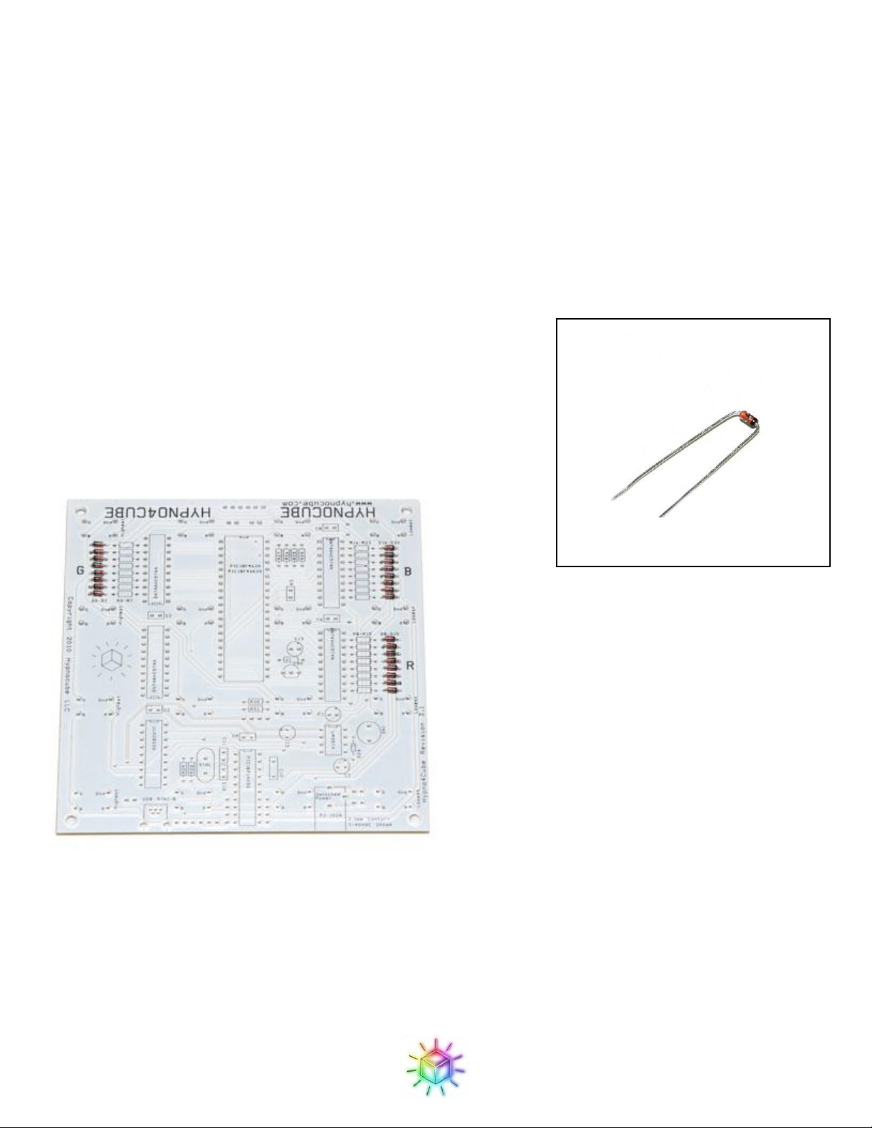
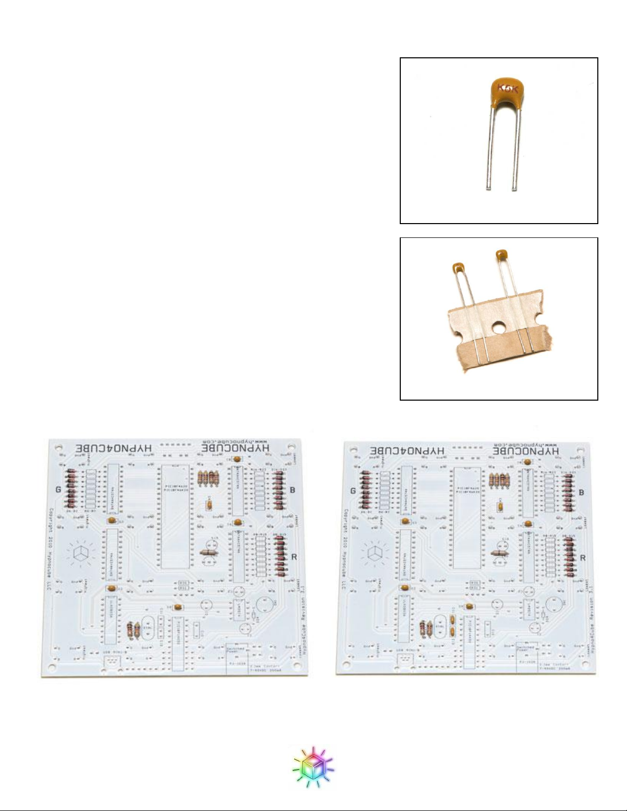
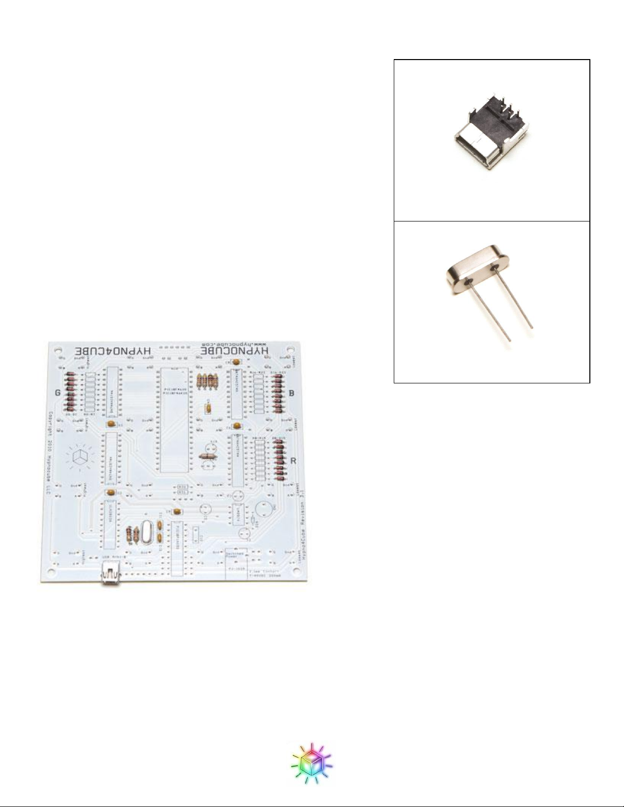
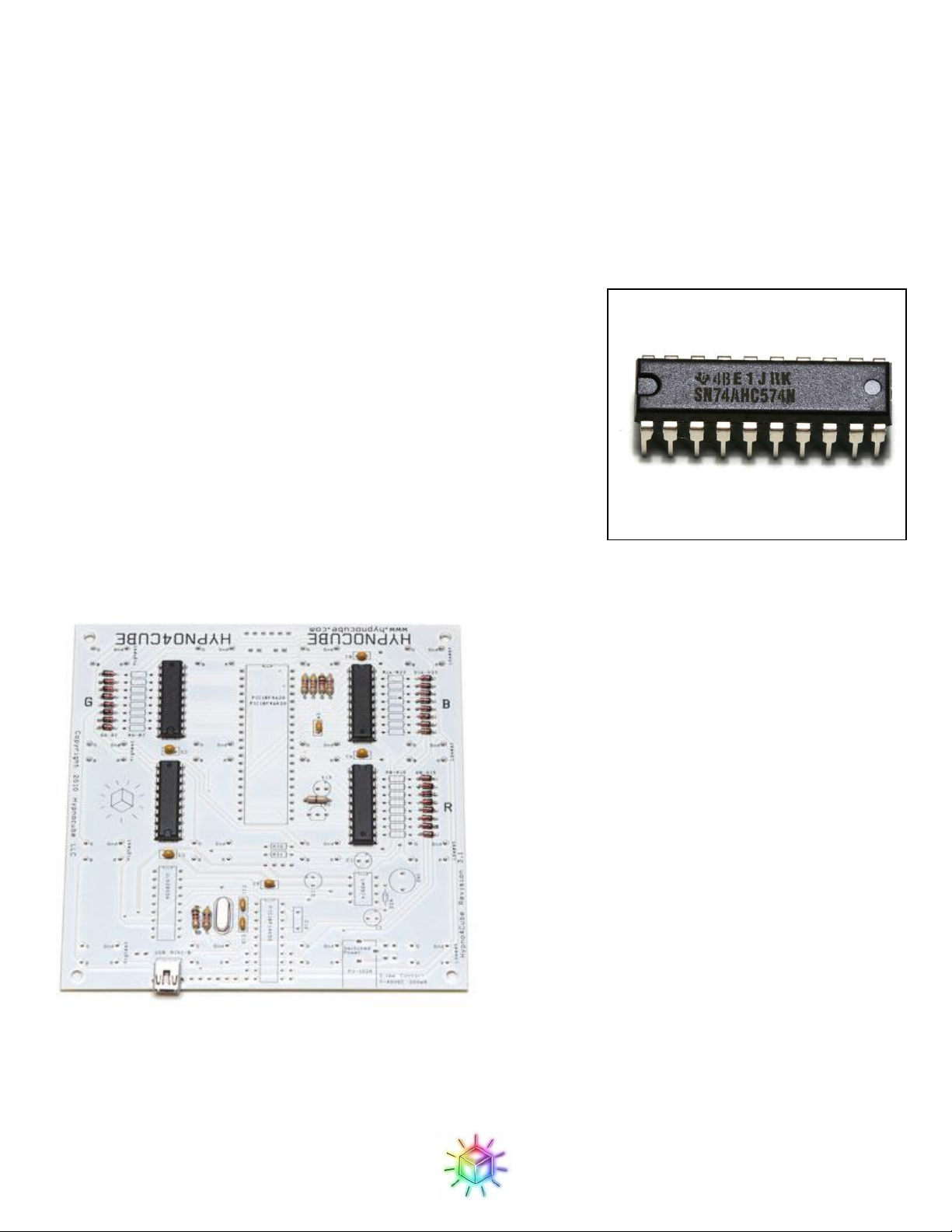
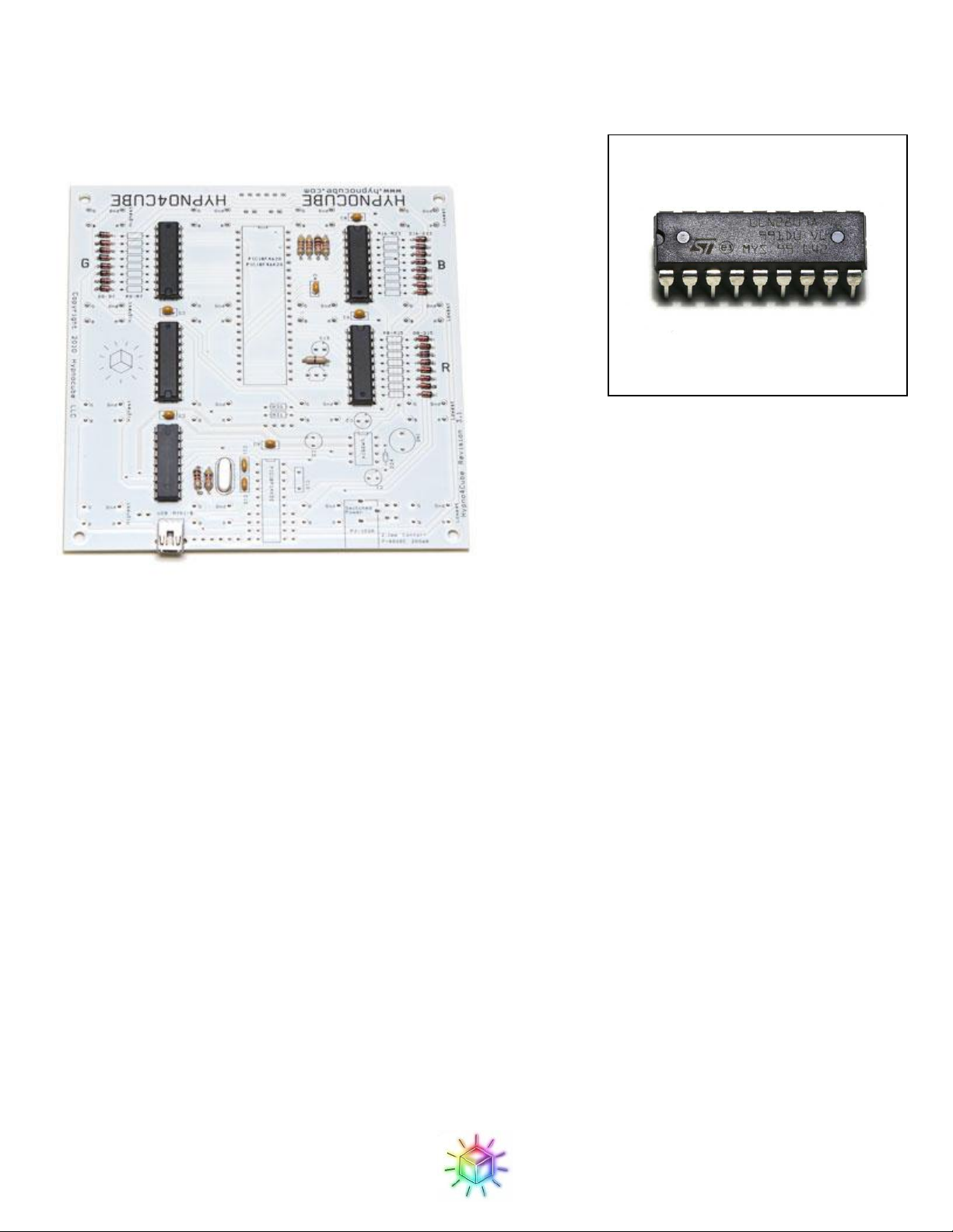
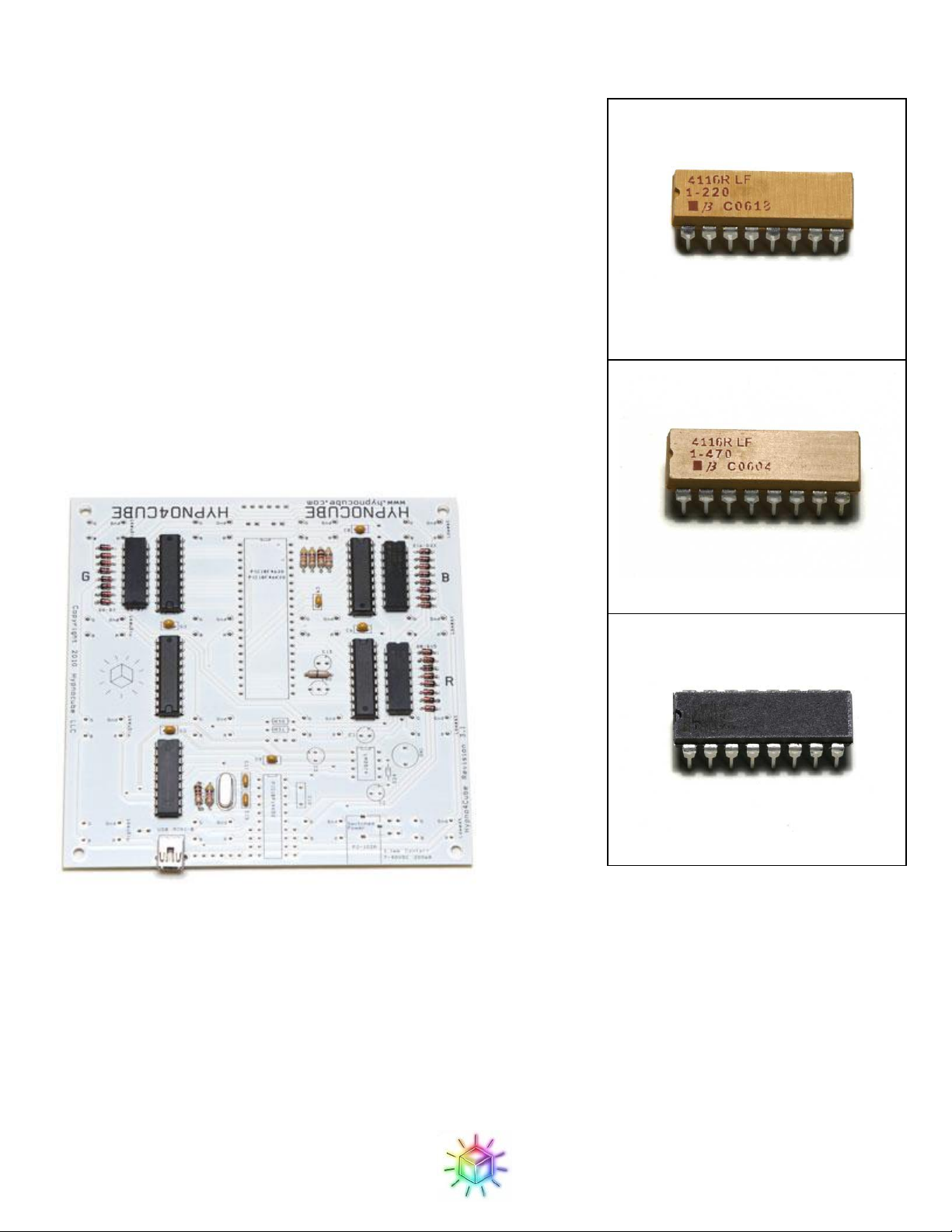
In “The Good” we construct the circuit board. This should be similar to any other electronics kit.
In “The Bad” we will construct four planes of LEDs, each being a 4×4 grid. This is the hardest part of the kit.
In “The Ugly” we will attach the LEDs to the PCB, testing as you go, and finally put it all together in the case.
Tools
You will need the following minimum set of tools:
1. Soldering iron. Any iron can work, but a nicer one will make the job a lot easier.
2. Solder - we recommend 63/37 Sn/Pb rosin core. All normal electronics solders should work fine for the
PCB, but the wire lattice can be quite particular (see page 17 for more details.)
3. Hardened wire cutter. Take care not to damage a delicate pair on the steel lattice wire.
4. Wire strippers (for 24 AWG wire).
5. Needle nose pliers.
6. Small Phillips screwdriver.
To make the jig you'll also need one of the following:
1. Cardboard for making a poor jig.
2. Wood and wood tools for making a good jig.
Disclaimers!
Before you begin, some items to note:
1. READ EVERYTHING IN THE INSTRUCTIONS BEFORE YOU START! You will make a much
nicer cube by knowing where steps are leading before constructing items. The instructions attempt to
make the kit foolproof, but we all know that is impossible :) Don’t become a FAQ entry.
2. One good idea is to print out the instructions and cross off each paragraph as you finish it, to ensure you
don’t miss a sentence or instruction step. This can save you trouble later.
3. This kit assumes you have built electronic kits before, and are proficient at soldering items to a circuit
board. Chips and LEDs can be damaged from ESD and too much heat, so make sure you are properly
grounded and don’t hold the iron on the leads too long. Make sure all solder joints connect well.
4. Many of the parts in this kit require correct orientation (rotation). When mentioned there is a right way
and a wrong way to connect something, both of which look similar. Be sure to have them correctly
positioned before soldering.
5. The LEDs are difficult to bend correctly. Make sure you are EXTREMELY diligent in bending them
correctly.
6. Plan on spending some time constructing the kit. Chris’s first (and only) kit build took him about 10
hours, over three nights. Gene, with much experience (having constructed all others) can build one in
about four hours. We have heard from a number of first-time builders who report from 6 –12 hours.
Plan on setting aside at least that much time.
For a look at the finished cube see Figure 77.
Good luck :)

Hypnocube 4Cube Instructions v 6.5, December 2013
- 3 -
Part 1: The Good
Part one is assembling the controller PCB. This should be straightforward for anyone who has done PCB work;
there's nothing exotic here.
Estimated completion time: 1.5 - 3 hours.
We will start with the lowest-profile parts and work our way up, as that allows your working surface to hold the
parts in place while we solder the bottom. Besides that, there is no particular requirement for assembly order.
Step 1: Diodes
The first parts we will place are the 24 signal diodes. Orientation is
important here; make sure the black stripe on the diode aligns with the
stripe on the part outline. The diodes go in the three banks marked D0-
D7, D8-D15 and D16-D23.
Figure 2 shows the board with all diodes in place.
Figure 2: Diodes in place.
Figure 1: Diode

Hypnocube 4Cube Instructions v 6.5, December 2013
- 4 -
Step 2: Resistors
Next we will place the resistors and a jumper masquerading as a
resistor. We have three resistor values here, 1K(brown-black-red,)
47K(yellow-violet-orange) and 0(single black stripe). The 47K
resistors go in R24, R26, R27 and R28. The 1Kresistors goes in R25
and R29. Finally, the 0“resistor” goes across J1. Resistor orientations
do not matter.
Figure 4: Resistors in place.
Figure 3: 47K(left) and 1K(right)
resistors

Hypnocube 4Cube Instructions v 6.5, December 2013
- 5 -
Step 3: Small capacitors
Next solder the six 0.1uF and two 22pF ceramic capacitors, shown in
Figure 5 and Figure 6: 22pF ceramic capacitors.The two look very
similar so take care to not mix them up. The 0.1uF capacitors go in C4
through C9 (Shown if Figure 8: 0.1uF ceramic capacitors in place.)
The 22pF capacitors go in C11 and C12 as shown in Figure 7: 22pF
ceramic capacitors in place..
These ceramic capacitors are not orientation dependent.
Figure 8: 0.1uF ceramic capacitors in place.
Figure 5: 0.1uF ceramic capacitor
Figure 6: 22pF ceramic capacitors
Figure 7: 22pF ceramic capacitors in place.

Hypnocube 4Cube Instructions v 6.5, December 2013
- 6 -
Figure 9: USB jack
Figure 10: Crystal
Step 4: Crystal and USB jack
The mini USB jack and the crystal both have similar heights so we’ll
do them together next.
The USB jack might be a bit tricky since it has a smaller pin spacing
then any of the other components, and the leads are barely long
enough to go through the PCB (it was, however, the only through-hole
mini USB jack I could find, and I figured many of you would prefer it
to the common surface mount variety.) Solder one of the large support
legs first, and make sure that the jack is reasonably well aligned, as
there is a bit of wiggle room in placement. Make sure that the solder
flows into the holes to make good contact with the USB pins. Also
make sure to solder the other support leg to give the jack extra support
during insert/removal of the plug.
The crystal on the other hand is a simple affair, and goes in the spot
marked ‘XTAL’. It is not orientation sensitive.
Figure 11: USB jack and crystal in place.

Hypnocube 4Cube Instructions v 6.5, December 2013
- 7 -
Step 5: Chips, dips, chains, whips...
It's time to place some chips. When the chips are down....
ICs can be damaged by static from your fingers, so ground yourself as usual when working with static-sensitive
electronics.
The chips usually don't quite fit since their pins are splayed a little wider than the PCB slots. It might help to
bend the pins slightly before inserting. Use a flat right-angle surface to bend them all slightly and at once.
We will start with the 4 SN74AHC574N chips (Figure 12)
Be sure to orient the chip properly! There is a notch on one end of the
chip (to the left in the picture above,) and this should align with a notch
drawn on the PCB footprint. Note that two of the SN74s face the
opposite direction as the other two SN74s –make sure they are all
oriented properly.
It can be helpful to tack the chip by soldering just 2 corner pins in
place, and making sure that the chip is properly seated before soldering
the rest. Uneven seating won't harm anything, but may not look very
good either. It's also good to double-check that the chip is oriented
properly - you really don't want to be trying to extract one after it's all soldered in.
Figure 13: SN74AHC574Ns in place.
Figure 12: SN74AHC574N

Hypnocube 4Cube Instructions v 6.5, December 2013
- 8 -
Next do the ULN2803A (Figure 14.) Again, note the orientation –it’s the opposite of the other ICs on that side
of the board, so it’s particularly easy to get wrong.
Here’s the board with the first set of chips in place.
Figure 15: ULN2803As in place.
Figure 14: ULN2803A

Hypnocube 4Cube Instructions v 6.5, December 2013
- 9 -
Step 6: Resistor arrays
These are just an array of resistors packaged into a chip which we
decided to use over discrete resistors for convenience. Note that the
footprints on the PCB still show the individual resistors. Since these are
just resistors in a fancy package, the orientation does not matter. Each
package is labeled with their resistance value; make sure you place
each one in the correct spot. R0 –R7 (the green resistors, and marked
‘G’ on the PCB) is 47, R8 –R15 (red, ‘R’) is 68, and R16 –R23
(blue, ‘B’) is 22.
The resistor arrays have been transitioning from a yellow package to
black. The 22and 47shown here are yellow, but chances are good
yours will be all black. The markings should be the same however.
The label on the 68package is impossible to read on the picture here,
but it’s there.
Figure 19: Resistor arrays in place.
Figure 16: 22resistor array
Figure 17: 47resistor array
Figure 18: 68resistor array

Hypnocube 4Cube Instructions v 6.5, December 2013
- 10 -
Step 7: The PICs
We have two PIC microcontrollers, one running the main firmware and
the second handling USB duties.
The Big Kahuna is the PIC18F4620. Just make sure you put it in the
correct orientation. The tab goes towards the edge of the board. If you
plan to reprogram your PIC be sure to read the Appendices and use a
socket before soldering down the PIC.
The second PIC is the PIC18F14K50 and goes at the bottom of the
board. It has the same orientation as the 18F4620.
Figure 22 shows the PCB with all of the chips in place.
Figure 22: PIC18F4620 in place.
Figure 20: PIC18F4620
Figure 21: PIC18F14K50

Hypnocube 4Cube Instructions v 6.5, December 2013
- 11 -
Step 8: Large(r) capacitors
Lastly, there are two capacitors that sit the highest.
One is the blue 0.47uF capacitor. It goes in C10, next to the bottom
PIC. It is not orientation sensitive.
The second is the 10uF electrolytic capacitor. Electrolytic capacitors
are orientation dependent - you will see a + symbol on the PCB for the
positive wire, which is the longer of the capacitor leads. The negative
lead is also marked on the body of the capacitor.
The 10uF capacitor goes in C3.
Figure 26: All PCB components in place.
Figure 25: 10uF electrolytic capacitor
Figure 23: 0.47uF capacitor
Figure 24: 10uF electrolytic capacitor.

Hypnocube 4Cube Instructions v 6.5, December 2013
- 12 -
Part 2: The Bad
In "The Bad" we will construct the LED lattice. This will consist of four steps: bending the LED leads into the
required shape, soldering the LEDs into eight strips of eight LEDs each, then soldering the strips into an 8×8
grid, and finally cutting this grid CAREFULLY into four separate 4×4 grids. Along the way we will need to
construct a couple of jigs to hold the LEDs as we work.
This is the most challenging part of constructing the cube. We recommend that you read this section thoroughly
to understand what is going to happen. Your cube will be much easier to make, less likely to have mistakes, and
will cause you less grief if you understand this entire section before starting it. Plus doing this part very
carefully will make your LEDs line up nicely, improving the aesthetic appeal.
Estimated completion time: 2.5 - 5 hours.
Step 1: Bend the LEDs
Look at the 3-channel RGB LED in Figure 27. There is a flat side, next to the red pin. The ground pin is
longest, and is next to the red pin. Note the kit has extra LEDs besides the 64 needed to complete the kit.
Figure 27: Unbent LED.
This part is tricky, so pay close attention. The leads from each of the 64 LEDs must be bent as in Figure 28 and
Figure 29.
Do not bend any yet! Read this section very carefully several times before starting to bend LEDs. Bending the
leads back and forth too many times will break the leads. In all the cubes we have built we have broken none
yet, but just in case we shipped you at least one extra LED.

Hypnocube 4Cube Instructions v 6.5, December 2013
- 13 -
The pins are bent as follows:
1. The first lead (the red lead, next to the flat spot) is bent as close to the base as possible, and MUST GO
IN THE DIRECTION INDICATED. Make sure you do not bend in the opposite direction.
2. Lead number 2, the ground, is left alone and sticks straight out.
3. Next bend lead number 4, the green lead, to go in the opposite direction of the red lead.
4. Lead number 3, the blue lead, is bent at about a 30 degree angle from the green lead.
Wires will be dropped from the red, green, and blue leads down to the PCB and into the holes labeled R, G, B.
Figure 28 is what the LEDs look like once bent.
Figure 28: Properly bent LED.

Hypnocube 4Cube Instructions v 6.5, December 2013
- 14 -
Figure 29: Rendering of a properly bent LED.
Now, bend one LED, which will be your template to follow while bending the other LEDs. I recommend
bending one LED, then double, triple, and quadruple checking that it is EXACTLY like the above pictures.
Once you are convinced you have a perfectly bent LED, set it aside and use it as a reference when you bend the
rest of them to check that all are the same orientation.
Now we will need to bend 8 more LEDs to make the first strip. You can do each LED one at a time by hand, or,
if you are using a wood jig, bend the LEDs in place in the jig, which can be a little easier and faster as the jig
will hold the LED for you and allow you to use both hands to bend the pins. If you opt for the cardboard jig,
then most likely the cardboard won’t hold the LED tightly enough to facilitate bending the pins.
Figure 30 and Figure 31 show the wood jig holding the LEDs before and after bending. This can be combined
with the step below to make strips while bending the LEDs, saving some time.

Hypnocube 4Cube Instructions v 6.5, December 2013
- 15 -
Figure 30: Unbent LEDs in jig.
Figure 31: Bent LEDs in jig.
Another good idea is to draw a picture on the jig showing how the LED sits and how the pins bend, as one of
our customers has done.

Hypnocube 4Cube Instructions v 6.5, December 2013
- 16 -
Figure 32: Wood jig with LED drawing.
When using this method, it is critical that you insert the LED in the hole in the proper way. A backwards LED
probably won't be noticed until it's in the cube and you find that a LED doesn't light or a column of LEDs lights
erratically.
Step 2: Create LED strips
If you haven’t already created a wood jig for the previous step, you will need to make one to solder the LEDs in
to strips.
You have two options: the cardboard jig and the wood jig. The wood jig is more stable and makes it easier to
build the cube, and is recommended. The cardboard jig also works, but is more flimsy.
(One of our customers, Rob Sheldon, designed a much better jig and provided us with instructions for
making it. If you can handle a hand drill, you should make this jig. Check out the Appendix 2 for
instructions on constructing this jig.)
The jig requires 8 holes to hold 8 LEDs evenly spaced in a straight line. The spacing between each LED should
be 1.25 inches (or 3.17cm to you civilized folks overseas.) To confirm that you have the proper spacing you can
compare it against the PCB; it should match the spacing between each GND hole on the LED footprints on the
PCB.
For a cardboard jig, you will want a piece of cardboard - stiffer the cardboard is better - about 12 inches (30cm)
long and 3 –4 inches (6 –10cm) wide. The extra width is so that the cardboard can be held vertically between
two sturdy objects, such as books. Wood is thicker and sturdier, and can provide its own base, so for a wood jig
a 12” x 1” (30cm x 3 cm) is sufficient, although it can of course be bigger (no need go through the trouble of
cutting down a piece you already have.)

Hypnocube 4Cube Instructions v 6.5, December 2013
- 17 -
Make 8 equally spaced marks on the jig, and then make 8 holes of LED diameter. A pen punches holes fine in
cardboard, and a drill works for the wood jig shown above.
Next place 8 LEDs in the jig, as in Figure 33 and Figure 36. The LEDs must all be rotated in the same
orientation, with the red and green leads pointing parallel to the axis of the jig holes. On the cardboard jig, the
green wires should be on the edge with the blue (angled) wire pointing towards the center.
Figure 33: A cardboard jig with LEDs.
Next we will be soldering a wire across the LEDs.
First, a note on solder. We’re about to solder to galvanized steel, which some people will tell you is insane.
Well, it’s a bit loopy, but works well given the right solder. I use 63/37 Sn/Pb solder, which works quite well. I
believe 60/40 works as well. 50/50 may not work, and I know the lead-free solders I’ve tried were miserable.
Before attaching the cross wires, note there is a correct and incorrect side for the cross wire as shown below.
The reason to lay them on this side is to provide more room to connect the red drop wires later. Note in these
computer rendered images exaggerate the proximity of the LEDs, and show the red and blue leads intersecting;
in real life they may be just touching, but this is not a concern as they will be trimmed down at a later step.
All that we will be soldering in this step the yellow cross wires to each gray ground wire, connecting 8 LEDs
into a single strip.

Hypnocube 4Cube Instructions v 6.5, December 2013
- 18 -
Figure 34: The cross wire (yellow) position.
Figure 35: The cross wire (yellow) position.
Now you can solder a wire down as in Figure 34, with the cross wire on the correct side and centered, with
equal amounts hanging off either ends. You want to solder fairly close to the LED, at the same distance all the
way across, and at the same height on ALL eight strips you will make. The small flat spot on the LED lead is a
good reference point, but the exact distance isn't critical –the point is to be consistent.

Hypnocube 4Cube Instructions v 6.5, December 2013
- 19 -
Figure 36: The cross wire atop the LED ground wires.
Figure 37: Close-up of cross wire soldered onto an LED.
To hold the cardboard jig stable while soldering, two books work well, as shown Figure 38. Do not let the cross
wires touch any leads besides the ground leads from the LEDs.

Hypnocube 4Cube Instructions v 6.5, December 2013
- 20 -
Figure 38: Soldering the LED strip on a cardboard jig.
Soldering here can be tricky, since the long wires are galvanized steel (steel was necessary to provide sufficient
structural strength, and also wasn't too expensive to get pre-straightened in low quantities.) Steel holds
considerably more heat than the tinned copper you are probably used to, and consequently will both take longer
to heat up (making cold solder joins more likely) and longer to cool off (the solder will take longer to solidify,
allowing the wire to move for a couple seconds after removing the iron.)
Because the wire takes longer to heat, we have to be careful about not damaging the LED. The best technique
I've found is to hold the cross wire down with the iron, and letting solder wick around the bottom to the LED
lead. This ensures that you get the cross wire hot enough for a good join, but you don't run the risk of damaging
the LED by holding the iron directly on the LED lead for too long while waiting for the cross wire to heat up.
You can start at one end and work towards the other, or start at the middle and work out towards the ends (the
method I generally prefer.) Try them both and use the one that works better for you. However, don't solder the
ends first and work to the middle, as this can cause the spacing to be off if the wire isn't perfectly straight.
Again, make sure the cross wire is centered! We will use the ends to hold the strips in a jig at a later step, and
you will need wire sticking out equally from both ends.
Once the all eight LEDs are secure, carefully wiggle the strip out of the jig. Pulling gently on the grounds that
stick straight out is a good strategy.
Congratulations! You should now have one strip, and it should look like Figure 39. Take some time to double
and triple check it against the instructions. Check the orientations of the LEDs, the side the ground wire is on,
and that the cross wire is centered.
Other Hypnocube Lighting Equipment manuals
Popular Lighting Equipment manuals by other brands

ARANCIA
ARANCIA C10071 installation guide

NightSearcher
NightSearcher Kanga Star 10K instruction manual

iSolutions
iSolutions Xperior 700SZ Spot user guide

Harbor Freight Tools
Harbor Freight Tools ONE STOP GARDENS 57684 Owner's manual & safety instructions

HERA
HERA Leoline Series installation guide

Polygroup
Polygroup SUMMER WAVES ST1100 owner's manual