manuals.online logo
Brands
  1. Home
  2. •
  3. Brands
  4. •
  5. Hyster
  6. •
  7. Forklift
  8. •
  9. Hyster A416 Operating instructions

Hyster A416 Operating instructions

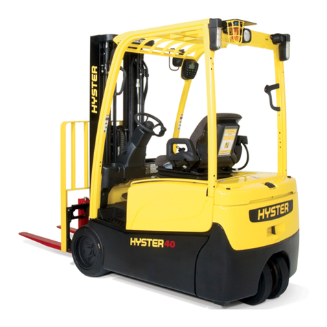
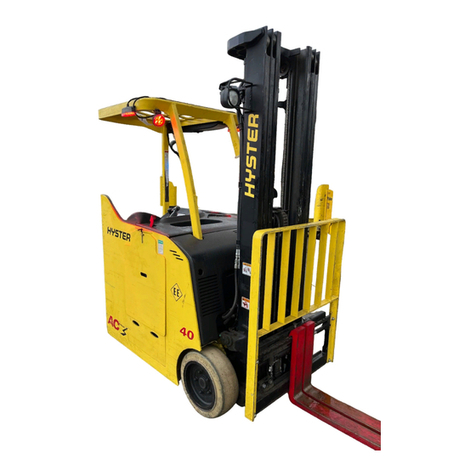
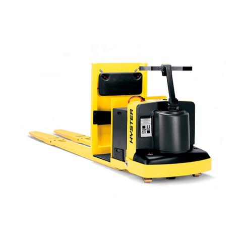
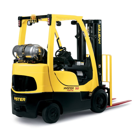
Hyster A416 (J2.00XM, J2.50XM, J3.00XM, J3.20XM, J40Z,
J50Z, J60Z) Forklift
TROUBLESHOOTING
AND ADJUSTMENTS
USING THE AC
CONTROLS PROGRAM
J2.00-3.20XM (J40-60Z) [A416]; V30ZD [D210];
E1.50-2.00XM (E25-35Z, E40ZS) [E114];
E2.00-3.20XM (E45-65Z) [G108]
PART NO. 1534737 2200 SRM 1058
SAFETY PRECAUTIONS
MAINTENANCE AND REPAIR
•When lifting parts or assemblies, make sure all slings, chains, or cables are correctly
fastened, and that the load being lifted is balanced. Make sure the crane, cables, and
chains have the capacity to support the weight of the load.
•Do not lift heavy parts by hand, use a lifting mechanism.
•Wear safety glasses.
•DISCONNECT THE BATTERY CONNECTOR before doing any maintenance or repair
on electric lift trucks.
•Disconnect the battery ground cable on internal combustion lift trucks.
•Always use correct blocks to prevent the unit from rolling or falling. See HOW TO PUT
THE LIFT TRUCK ON BLOCKS in the Operating Manual or the Periodic Mainte-
nance section.
•Keep the unit clean and the working area clean and orderly.
•Use the correct tools for the job.
•Keep the tools clean and in good condition.
•Always use HYSTER APPROVED parts when making repairs. Replacement parts
must meet or exceed the specifications of the original equipment manufacturer.
•Make sure all nuts, bolts, snap rings, and other fastening devices are removed before
using force to remove parts.
•Always fasten a DO NOT OPERATE tag to the controls of the unit when making repairs,
or if the unit needs repairs.
•Be sure to follow the WARNING and CAUTION notes in the instructions.
•Gasoline, Liquid Petroleum Gas (LPG), Compressed Natural Gas (CNG), and Diesel fuel
are flammable. Be sure to follow the necessary safety precautions when handling these
fuels and when working on these fuel systems.
•Batteries generate flammable gas when they are being charged. Keep fire and sparks
away from the area. Make sure the area is well ventilated.
NOTE: The following symbols and words indicate safety information in this
manual:
WARNING
Indicates a condition that can cause immediate death or injury!
CAUTION
Indicates a condition that can cause property damage!
Troubleshooting and Adjustments Using The AC Controls Program Table of Contents
TABLE OF CONTENTS
General ............................................................................................................................................................... 1
Computer Requirements ............................................................................................................................... 1
Software, Install ............................................................................................................................................ 1
Language Selection........................................................................................................................................ 1
Demo Mode..................................................................................................................................................... 2
Connect PC to Lift Truck............................................................................................................................... 4
Starting AC Controls Program ..................................................................................................................... 4
Lift Truck Control Setup ................................................................................................................................... 9
Change Lift Truck Serial Number or Hourmeter ........................................................................................ 9
Setting Factory Default Values or Changing Lift Truck Parameters......................................................... 10
Create New Custom Lift Truck Configuration............................................................................................. 13
Lift Truck Configuration Properties............................................................................................................. 17
Import New Lift Truck Configuration From Disk ....................................................................................... 20
Delete Custom Lift Truck Configuration or Password File......................................................................... 22
Dash Display ...................................................................................................................................................... 24
Custom Display Languages .......................................................................................................................... 24
Download Display Language ........................................................................................................................ 26
Clear Operator Log........................................................................................................................................ 28
Clear Status Log............................................................................................................................................ 29
Password Functions........................................................................................................................................... 30
Enable/Disable Password and Lift Truck Inspection Functions................................................................. 30
Truck Inspection Checklist ....................................................................................................................... 30
Password.................................................................................................................................................... 30
Password Properties...................................................................................................................................... 32
Create New Password File............................................................................................................................ 35
Download Passwords..................................................................................................................................... 36
Upload Passwords.......................................................................................................................................... 38
Reports Menu..................................................................................................................................................... 40
Passwords....................................................................................................................................................... 40
Status Codes .................................................................................................................................................. 43
Operators ....................................................................................................................................................... 46
Current Settings ............................................................................................................................................ 49
Troubleshooting.................................................................................................................................................. 52
Diagnostics..................................................................................................................................................... 52
Help Menu.......................................................................................................................................................... 55
General........................................................................................................................................................... 55
Contents ......................................................................................................................................................... 55
Technical Support .......................................................................................................................................... 57
About Electric Truck AC Controls Program................................................................................................. 57
This section is for the following models:
J2.00-3.20XM (J40-60Z) [A416];
V30ZD [D210];
E1.50-2.00XM (E25-35Z, E40ZS) [E114];
E2.00-3.20XM (E45-65Z) [G108]
©2003 HYSTER COMPANY i
Thanks very much for your reading,
Want to get more information,
Please click here, Then get the complete
manual
NOTE:
If there is no response to click on the link above,
please download the PDF document first, and then
click on it.
Have any questions please write to me:
admin@servicemanualperfect.com
"THE
QUALITY
KEEPERS"
HYSTER
APPROVED
PARTS
2200 SRM 1058 General
General
The information contained in this manual gives the
user a brief overview of the Electric Truck AC Con-
trols Program. This manual also explains the com-
mondrop-downmenufeaturesfortheuserthatare
listed under the File menu, the Reports menu, the
Tools menu, and the Help menu.
A personal computer (PC) can be used to set the trac-
tion motor and pump motor controller functions, read
status codes, and perform numerous diagnostic and
troubleshooting functions.
COMPUTER REQUIREMENTS
The PC must have the following minimum configu-
ration.
1. Either Microsoft®Windows 98™ or Microsoft
Windows 2000™ or later operating system must
be installed.
2. TheremustbeanopenUniversalSerialBus
(USB) port available on the computer to connect
to the lift truck.
3. There must be a compact disk read-only-memory
(CD-ROM) drive installed on the computer.
4. Microsoft Internet Explorer™ Version 5.01
or later must be installed on the computer.
5. The display screen resolution should be set to
800×600 pixels.
SOFTWARE, INSTALL
NOTE: See instructions included with CD and/or
readme.txt file on the CD for additional instruc-
tions and possible password requirements.
NOTE: When installing the software on a PC with
Microsoft Windows 2000, make sure that the
computer is setup with Administrator rights on
the computer.
NOTE: In the following examples, the D: drive repre-
sents the CD-ROM drive. The CD-ROM drive could
be a different letter on the computer.
To run the setup program, follow these steps:
1. Place the CD in the CD-ROM drive. Installation
will start automatically if the computer is set for
automatic start-up. If the computer is not set for
automatic start-up, go to Step 2.
2. Click Start.
3. Select Run and in the Open line enter
D:\setup.exe.
4. Click OK. The setup program will guide you
through the rest of the steps to install the Elec-
tric Truck AC Controls Program Hyster on the
computer.
It is recommended that the program is installed to
the default directories.
LANGUAGE SELECTION
1. Select the Language tab. SeeFigure1. Click
the drop-down list and select one of the following
languages:
•English
•German
•French
• Italian
•Spanish
2. When the desired language has been selected,
click OK to update the Options section. The
Electric Truck AC Controls Program Hyster text
will appear in the selected language.
1
General 2200 SRM 1058
Figure 1. Language Options
DEMO MODE
1. Select Options from the File menu. An Option
pop-up box appears with a General tab and Lan-
guage tab. SeeFigure2.
NOTE: In the Options dialog box, on the General
tab, if the Normal button is selected, the system is
in the default status for operation and must be con-
nected to an actual lift truck. See Figure 2.
If the Demo button is selected, the program is in the
demonstration mode, and the program can be oper-
ated without being connected to an actual lift truck.
SeeFigure2.
2. Select the General tab and click the Demo se-
lection.
2
2200 SRM 1058 General
Figure 2. Options Menu
3
General 2200 SRM 1058
CONNECT PC TO LIFT TRUCK
To connect the Interface Cable Kit Hyster part num-
ber 1534010 to the lift truck wire harness, follow
these steps:
1. Connect the USB connector of the Interface Ca-
ble to the USB port on the PC. See Figure 3.
1. INTERFACE CABLE
2. LAPTOP COMPUTER
3. INTERFACE CABLE EXTENSION
4. LIFT TRUCK WIRING HARNESS
Figure 3. Interface Cable Kit Connected to USB
Connector
2. If provided, connect the nine-pin connector of the
Interface Cable extension to the Interface Cable.
SeeFigure3.
3. Connect the three-pin connector of the Interface
Cabletothelifttruckwiring harness three-pin
connector which is located behind the dashboard
cowl liner cutout under the dash display. See
Figure 3. Connection between the PC and lift
truck is now complete.
4. Connect the battery.
5. Connect the lift truck power by lifting the red
battery disconnect button, if the lift truck is so
equipped.
6. Turn the key switch to the ON position. See Fig-
ure 4.
1. BATTERY DISCONNECT SWITCH - J2.00-3.20XM
(J40-60Z) [A416] MODELS ONLY
2. KEY SWITCH
Figure 4. Power Switches
STARTING AC CONTROLS PROGRAM
1. Connect the PC to the lift truck. See Connect PC
to Lift Truck.
2. Double-click the Electric Truck AC Controls Pro-
gram Hyster icon located on the desktop. See
Figure 5.
4
2200 SRM 1058 General
Figure 5. Desktop
5
General 2200 SRM 1058
3. Click the appropriate Factory or Custom file
folder for correct configuration of the lift truck.
SeeFigure6.
4. Select Connect on the File menu, or click the
Connect icon on the toolbar menu in the upper
left corner. See Figure 6 and Figure 7.
NOTE: On the computer, under the Tools menu, the
red Xthat appears in the Computer Connection
icon changes to an arrow →which indicates connec-
tion and communication between the computer and
lift truck. See toolbar icon Figure 7.
Figure 6. Connected to Lift Truck
6
2200 SRM 1058 General
Figure 7. File Menu, Connect PC to Lift Truck
7
General 2200 SRM 1058
NOTE: If the connection fails between the computer
and lift truck, an error screen will appear. See Fig-
ure 8.
5. If this connection error appears on the computer
screen, check all connections between the com-
puter and the lift truck. Also, check that the bat-
tery connect/disconnect switch is engaged, if so
equipped, and that the key switch is in the ON
position.
Figure 8. Communication Error PC to Lift Truck
8
2200 SRM 1058 Lift Truck Control Setup
Lift Truck Control Setup
This section includes the following processes:
Change Lift Truck Serial Number and Hourme-
ter,Setting Factory Default Values or Chang-
ing Lift Truck Parameters,Create New Custom
Lift Truck Configuration,Lift Truck Config-
uration Properties,Import New Lift Truck
Configuration from Disk,andDelete Custom
Lift Truck Configuration or Password File.
CHANGE LIFT TRUCK SERIAL NUMBER
OR HOURMETER
1. From the Tools menu, click Individual Setup.
See Figure 9. An Individual Setup dialog box
pops up with the following information on the lift
truck. See Figure 10.
Figure 9. Tools Menu Individual Setup
9
Lift Truck Control Setup 2200 SRM 1058
Figure 10. Individual Setup Menu
Parameter: Represents the lift truck function name
that can be setup on the lift truck and is changeable.
The items that are listed in this column are: lift truck
serial number, traction hours, and pump hours.
NOTE: The New Value column should be blank, un-
less the user has entered new values in this column
before downloading this information to the lift truck
display panel.
NOTE: If the Master Controller is replaced, the lift
truck serial number SHOULD be entered in the
New Value column.
New Value: Displays the new value input by the
user.
Truck Value: Displays values for that specific lift
truck that have been stored in the lift truck master
controller.
2. Input desired values in the New Value column.
3. Click Download button to download New Val-
ues to the lift truck.
NOTE: If the traction motor or pump motor is re-
placed, the traction or pump hours can be changed to
zero. If the Master controller is replaced, the Truck
Value will be shown as zero for the hourmeters.
They can be updated, if desired, from this screen.
SETTING FACTORY DEFAULT VALUES OR
CHANGING LIFT TRUCK PARAMETERS
NOTE: Make sure there is a connection between the
lift truck and the computer before making adjust-
ments through the Tools menu. See the Connect PC
to Lift Truck section for more information.
1. Select a Custom Configuration file or Factory
Configuration file from the drop-down list.
10
2200 SRM 1058 Lift Truck Control Setup
2. From the Tools menu, click System Setup.See
Figure 11. A System Setup-Connected dialog boxpopsupwiththefollowinginformationonthe
lift truck. See Figure 12 and Figure 13.
Figure 11. Tools Menu System Setup
11
Lift Truck Control Setup 2200 SRM 1058
Figure 12. Custom Configuration Setup
Parameter: Represents functions that can be
setup on the lift truck and are changeable.
Factory/Custom Value: Represents the value
for either the Factory Configuration or Custom
Value. The Truck Value can be changed in this
column.
Truck Value: Represents the actual value that
has been stored in the lift truck control.
NOTE: If there is a difference in value between the
Factory/Custom Value column and Truck Value
column, the row where the difference occurs will be
highlighted in yellow. This indicates that the current
lift truck value is NOT at the default setting.
NOTE: All values in the Factory/Custom column
will be downloaded to the lift truck when the Down-
load Button is clicked.
3. To change a value in the Truck Value column,
click on the item to be changed in the Factory/
Custom column.
12
2200 SRM 1058 Lift Truck Control Setup
NOTE: ThenewvaluemustbeenteredintheFac-
tory/Custom Value columnanddownloadedtothe
lift truck to change the Truck Value column.
4. Enter the new value in the Factory/Custom
Value column.
5. Click the Download button to download the new
values to the lift truck. See Figure 13.
6. Click the Apply button to save Custom Values to
the Custom Configuration file. See Figure 12.
Figure 13. System Setup Change Screen
CREATE NEW CUSTOM LIFT TRUCK
CONFIGURATION
NOTE: Before changing cables between lift trucks,
make sure the previous lift truck information is
saved on the computer, or the information will be
lost and need to be reentered.
1. Click the Connect/Disconnect icon to discon-
nect the computer from the lift truck.
2. Disconnect the Interface Cable from the three-
pin connector located behind the dashboard cowl
liner cutout under the dash display.
13
Lift Truck Control Setup 2200 SRM 1058
3. Click New Truck Configuration in the File
menu, or click the New Truck Configuration
File icon on the toolbar. See Figure 14.
Figure 14. New Truck Configuration
14

This manual suits for next models

7

Other Hyster Forklift manuals

Hyster D264 Operating instructions

Hyster

Hyster D264 Operating instructions

Hyster C219 Operating instructions

Hyster

Hyster C219 Operating instructions

Hyster H40-60XT User manual

Hyster

Hyster H40-60XT User manual

Hyster C476 Operating instructions

Hyster

Hyster C476 Operating instructions

Hyster MAST N50F Operating instructions

Hyster

Hyster MAST N50F Operating instructions

Hyster J40-65Z Guide

Hyster

Hyster J40-65Z Guide

Hyster F001 Operating instructions

Hyster

Hyster F001 Operating instructions

Hyster H8.00-12.00XM Operating instructions

Hyster

Hyster H8.00-12.00XM Operating instructions

Hyster L007 Operating instructions

Hyster

Hyster L007 Operating instructions

Hyster B60ZAC User manual

Hyster

Hyster B60ZAC User manual

Hyster H4.0FT5 Operating instructions

Hyster

Hyster H4.0FT5 Operating instructions

Hyster F114 User manual

Hyster

Hyster F114 User manual

Hyster J160 User manual

Hyster

Hyster J160 User manual

Hyster N35ZDR User manual

Hyster

Hyster N35ZDR User manual

Hyster A214 Operating instructions

Hyster

Hyster A214 Operating instructions

Hyster D210 Operating instructions

Hyster

Hyster D210 Operating instructions

Hyster A214 User manual

Hyster

Hyster A214 User manual

Hyster CHALLENGER H165XL User manual

Hyster

Hyster CHALLENGER H165XL User manual

Hyster W40Z Manual

Hyster

Hyster W40Z Manual

Hyster J2.00-3.20XM User manual

Hyster

Hyster J2.00-3.20XM User manual

Hyster B262 Operating instructions

Hyster

Hyster B262 Operating instructions

Hyster E3.50-5.50XL3 Operating instructions

Hyster

Hyster E3.50-5.50XL3 Operating instructions

Hyster C471 User manual

Hyster

Hyster C471 User manual

Hyster S70XL User manual

Hyster

Hyster S70XL User manual

Popular Forklift manuals by other brands

Hyundai 100D-7 operating manual
Hyundai

Hyundai 100D-7 operating manual

Kubota AP-PFL4548 Operator's manual

Kubota

Kubota AP-PFL4548 Operator's manual

Jungheinrich EKS 314 operating manual

Jungheinrich

Jungheinrich EKS 314 operating manual

Hyundai 12EPML Operation manual

Hyundai

Hyundai 12EPML Operation manual

EKKO EB13E manual

EKKO

EKKO EB13E manual

Presto Power Stak PPS2200-62NFO-27 Installation, operation and service manual

Presto

Presto Power Stak PPS2200-62NFO-27 Installation, operation and service manual

Noblift EFS Series operating instructions

Noblift

Noblift EFS Series operating instructions

morse 285A Operator's manual

morse

morse 285A Operator's manual

agrimac Carretillas Elevadoras TW16 Instruction and maintenance manual

agrimac

agrimac Carretillas Elevadoras TW16 Instruction and maintenance manual

PROFESSIONAL HYDRAULIC JACKS 60050 Operator's manual

PROFESSIONAL HYDRAULIC JACKS

PROFESSIONAL HYDRAULIC JACKS 60050 Operator's manual

Noblelift PS10M Service maintenance manual

Noblelift

Noblelift PS10M Service maintenance manual

Still EK-X Original instructions

Still

Still EK-X Original instructions

Hyundai 110DF-7 operating manual

Hyundai

Hyundai 110DF-7 operating manual

Manitou MRT 2150 Privilege Plus ST4 S2 Operator's manual

Manitou

Manitou MRT 2150 Privilege Plus ST4 S2 Operator's manual

SASFORKS SCORPION Operator's manual

SASFORKS

SASFORKS SCORPION Operator's manual

Viessmann 21751 manual

Viessmann

Viessmann 21751 manual

Terex Genie GTH-4013 Operator's manual

Terex

Terex Genie GTH-4013 Operator's manual

Still EXG-10 Original instructions

Still

Still EXG-10 Original instructions

manuals.online logo
manuals.online logoBrands
  • About & Mission
  • Contact us
  • Privacy Policy
  • Terms and Conditions

Copyright 2025 Manuals.Online. All Rights Reserved.