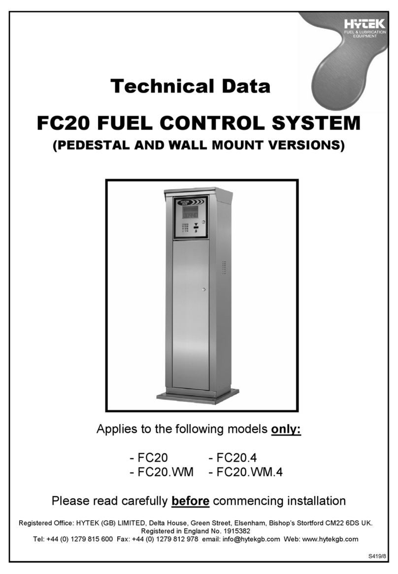
Hytek FC20 Instruction manual

S901/1
Technical Data
FC20 MID APPROVED
FUEL CONTROL SYSTEM
(COMPACT WALL MOUNT VERSION)
Applies to the following model only:
-FC20.WWM.C
Please read carefully before commencing installation
Registered Office: HYTEK (GB) LIMITED, Delta House, Green Street, Elsenham, Bishop’s Stortford CM22 6DS UK.
Registered in England No. 1915382
Tel: +44 (0) 1279 815 600 Fax: +44 (0) 1279 812 978 email: info@hytekgb.com Web: www.hytekgb.com

S901/1
ENVIRONMENTAL INFORMATION
European Directive 2012/19/EU requires that the
equipment bearing this symbol on the product an/or its
packaging must not be disposed of with unsorted municipal
waste. The symbol indicates that this product must be
disposed of separately from regular household waste
streams. It is your responsibility to dispose of this and
other electric and electronic equipment via designated
collection facilities appointed by the government or local
authorities.
PRODUCT DESCRIPTION
This system is approved in accordance with Welmec Guides 8.8,
7.2, 10.10 and OIML R117-1 Edition 2007 and has been issued
with a parts certificate issued by the NMO. It is suitable to be
connected to any fuel pump with a suitable MID approval
certificate. It bears the following parts certification marking and
number:
GB-1653
IMPORTANT WARNING NOTES
1. This system must not be sited adjacent to a petrol dispenser or
in any other hazardous zone.
2. Installation of this equipment should only be carried out by
qualified fuel installation engineers.
3. The installation must conform to all relevant electrical and local
authority regulations and standards.

S901/1
4. The pump must be located and installed in a climatic
environment in accordance with the following:
Temperature : -20°C to +45°C
Humidity : Class H3 (open location with
average climatic conditions)
Environment : Open and condensing
Mechanical : Class M1 (location with vibration of
low significance)
Electrical Disturbance : E1 (located in residential, commercial
and light industrial environments)
INSTALLATION INSTRUCTIONS
Check you have the following items:
1 x FC20.WWM.C fuel control system
1 x Top door key
2 x Override keys
1 x Wall mounting plate

S901/1
BACK PLATE DIMENSIONS

S901/1
MOUNTING
This FC20 unit has a stainless-steel mounting plate pre-fitted to the rear. To
remove the mounting plate ready for fitting please carry out the following
procedure.
1. Open the front door using the supplied key.
2. Remove the fuse panel by unscrewing the 2x small Allen bolts.
3. Remove the large Allen bolt securing the mounting plate. The rear
mounting plate can now be removed.
4. Fit the mounting plate to a suitable wall or structure.
5. Refit the FC20 unit to the mounting plate and tighten the large Allen
bolt to secure.
6. The fuse panel doesn’t need to be refitted yet.
FUSE PANEL ALLEN BOLTS MOUNTING PLATE
ALLEN BOLT

S901/1
ELECTRICAL CONNECTIONS
1. NB: The FC20 must have a continual 220/240V AC supply, even
when not in use.
2. To the lower right-hand side of the cabinet you will see the power
supply input terminal connectors.
3. Connect a constant 220/240V AC 50 Hz supply, fused at 13 amps, to
the 220/240V terminal block as shown below.
PUMP CONNECTIONS
Up to two pumps can be controlled via a connection using the Hytek
Modbus RS485 protocol. Connections are provided inside the pulse
connections junction box.Ensure all the terminal screws are tight and
replace the junction box covers.
FUSES
The FC20 unit has spare 1A fuses for mains power supply and spare 10A
fuses for the pump inputs.
BATTERY BACKUP POWER
The FC20 requires battery backup. The battery connector lead must be
plugged onto the logic board on installation, before powering up the pump.
Ensure the power is turned off to the system prior to opening the front door.
The onboard battery needs to be replaced every 12 months.
E N L

S901/1
CONNECTING THE ANTENNA:
The supplied antenna must be fitted in a secure location so that it cannot be
damaged.
Carefully fit the antenna lead connector to the modem ensuring that it
doesn’t cross thread on the connector. Do not over tighten.
The LED light on the modem will start flashing when the modem is online.
FINISHING THE INSTALLATION:
The fuse panel must now be refitting using the 2 x small Allen bolts.
Please see the operating manual for more information of how to use the
system.

S901/1
E.U. DECLARATION OF CONFORMITY
Company Name: Hytek (GB) Ltd
Address: Delta House, Green Street
Elsenham, Bishops Stortford
Hertfordshire
CM22 6DS, UK
Date of Issue: 13th August 2020
Equipment Details: Hytek FC20 Fuel Control Systems MID Certified
FC20.W, FC20.WWM, FC20.WWM.C
Applicable Directives: 2004/108/EC EMC Directive &
& Standards 2014/30/EU EMC Directive (effective date 20th April 2016)
EN 61000-6-3:2007 (+A1)
Electromagnetic compatibility (EMC) - Part 6-3: Generic
standards - Emission standard for residential, commercial
and light-industrial environments
EN 61000-6-2:2005
Electromagnetic compatibility (EMC) Part 6-2: Generic
standards - Immunity for industrial environments
2014/35/EU Low Voltage Directive
2006/42/EC Machinery Directive
2014/68/EU Pressure Equipment Directive
2012/19/EU Waste Electrical & Electronic Equipment
Regulations
2011/65/EU Restriction of Hazardous Substances
Directive (RoHS2)
OIML R117-1 Edition 2007
Welmec Guides 8.8, 7.2, 10.10
NMO Parts Cert.: GB-1653
Issuing Authority: National Measurement & Regulation
Office,Stanton Ave,Teddington
TW11 0JZ
Declaration Number: EU148/1
On behalf of the above-named company, I declare under our sole responsibility that,
on the date the equipment accompanied by this declaration is placed on the market,
the equipment conforms with all technical and regulatory requirements of the above
listed directives.
Clive Wellings, Technical Manager
13th August 2020, Bishops Stortford, Herts
Table of contents
Other Hytek Control System manuals