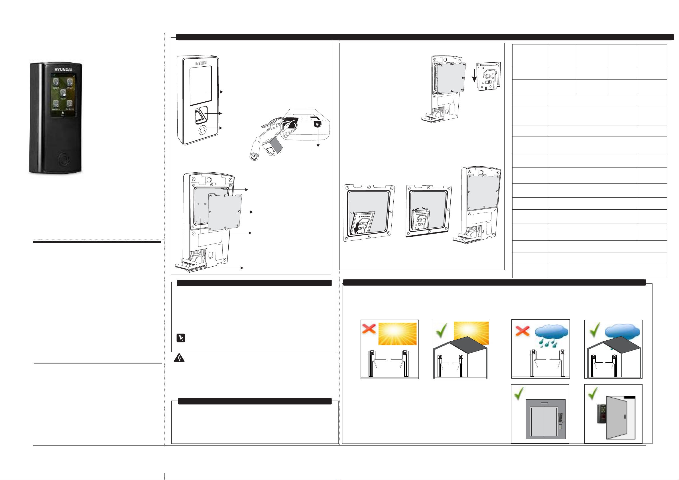
2Next LevelYes STQC CertifiedYes STQC CertifiedCard, Pin and FingerCard and PinCard, Pin and FingerCard, Pin and FingerYes NoSensorCredential SupportUser CapacityType of CardUSBCommunication PortReader Power OutputDoor Lock RelayDoor Lock PowerAuxiliary Outputs RelayInput PowerBuilt in POEBuilt in Wi-FiBattery BackupOperating TemperatureParametersSpecification50,000EM Prox, HID Prox, HID iclass & Mifare1 USB for Data Transfer and for 3G-4G dongleEthernet, Wi-Fi, Mobile Broadband (3G-4G)Internal 12 VDC @ 0.2ARelay SPDT, FormC, 1A@ 30 VDCInternal 12VDC @0.5A or ExternalRelay SPDT, FormC, 1A@ 30 VDC12 VDC @2AIEEE 802.3 af Class ; Max 12WYesNo Internal battery backup, External Through PSBBFAXQCAXFAXQEFAX00 0 C to +50 C
NoNoNo
No
Technical SpecificationReader Interface TypesRS232 and WiegandNoNo
Quick Installation Guide
Inserting Card Personality ModuleŸThere are no user-serviceable parts inside.ŸInstallation and servicing should be done only by a qualified technician.ŸUse this product only for the purpose for which it was designed.ŸOpening or removing the device cover may result in electric shock orexposure to other hazards.WARNINGWhat Your Package Contains ŸMounting Plate with screw M3/6Ÿ2 Screws M5/25Ÿ2 Screw GripsŸCOSEC VEGA Controller UnitŸPower Supply Cable (with DCJack)ŸExit Switch CableŸAuxiliary I/O CableŸQuick Installation GuideŸPower Adpator 12VDC,2AŸEM Lock CableŸEthernet Cable with RJ45 PlugCard Sensing AreaTouch Screen Display Finger SensorCable ConnectorsBack CoverCPM Slot(Card Personality Module)USB PortMounting Screw Hole1. Remove the back cover of yourdevice by removing all screws asshown in Figure 4. 2. Hold the Card Personality Modulewith the smooth surface towards you,and the narrower end facing down asshown in Figure 5.4. Press the free end of the module inwards with your fingertips to lockit in place as shown in Figure 7.3. Lower the module in this position into the CPM slot as shown inFigure 6.5. Replace the back cover as shown in Figure 8.1. Do not install the device in extremely hot temperature or under direct sunlighton turnstile or at extra bright places. This may affect the LCD and finger printsensor of device. You can do indoor installation or on the turnstile under the roofas shown in Figure9.5. Do not install the device in outdoor areas which may be exposedto rain, cold and dust. You can do indoor installation or on theturnstile under the roof as shown in Figure10.2. You can mount the device on a flat surface such as a wall or Elevator, close tothe access point (door) with surface wiring or concealed wiring as shown inFigure11.3. Recommended height from ground level is upto 4.5 feet.4 Do not install on unstable surfaces, near volatile inflammable materials, areas where volatile gas is created, where ferromagnetic field or noise is induced, where static is created, such as desks made of plastics, carpets. Front ViewBottom ViewRear ViewŸA Power DrillŸA screw driver setŸInsulation tapeŸA wire StripperThings You Will Need Technical SpecificationFigure1:Figure3:Figure2:Figure6Figure4Figure5
MATRIX COMSEC
Figure7Figure8Figure9Figure10
Pre-Installation Safety Instructions
Figure11MATRIX COMSECMATRIX COMSEC
CONTROLLER
Know Your ControllerPlease read this guide first for correct installation and retain it for future reference. The information in this guide has been authenticated at the time of publication. However, Hyundai
reserves the right to make changes in product design and specifications without prior notice.CopyrightAll rights reserved. No part of this document may be copied or reproduced in any form or by any means without the prior written consent of Hyundai.WarrantyLimited Warranty. Valid only if primary protection is provided, mains supply is within limit and protected, and environment conditions are maintained within product specifications. Complete warranty statement is available on our website:ŸA stand-alone computer with a web- browser tochange the network settings of controller.ŸAccess to Server application to configure controller on Server. Exit Switch cable, EM Lock cable, External Reader Cable and Auxiliary I/O Cable are not in the package of FAXQE.


