Hyundai HG200DP User manual

Head office: 16th floor of Wework Building, 507 Teheran-ro,
Gangnam-gu, Seoul
TEL: (02) 6230-6041 FAX: (02) 598-8467
Pohang Plant 2: 99 Yeongil Mansandan-ro 88beon-gil, Heunghae-eup,
Buk-gu, Pohang-si, Gyeongsangbuk-do
TEL: (054) 260 0664 FAX: (054) 260 0599
HG200DP (Double pulse)
User manual
To use this product correctly and safely
Please read this manual thoroughly before using, checking or repairing the product.

1
CONTENTS
- 1.Safety……………………..………………..…………………………….…..……....…………………………………………………….
2
- 2.General Description……...………......……...…………………….………...……….....………………………………………..
3
-3.Main Parameter…….……...…...........…….....………………………………….…..……….……………………………………
4
- 4.Structure of welder…….……...…...........………………………..…………….…..……….……………………………………
5
-5.Installation …………………………………………………………………………………………………………………………………..
7
-6.Operation…………………………………………………………………………………………………………………………………….
9
- 7.Trouble shooting…………………………………………………………..……….……………………………………………………
14
- 8.Semi-automatic welding specification table..……………………….………..……………………………………………
15
- 9.Tansport & Storage……………………………………………………...………………….....…......................................
17
This welding machine for industrial and professional use is in conformity with IEC974 International
Safety Standard.
Hereby we state that we provide 6 months of guarantee for this welding machine since the date of
purchase.
Please read and understand this instruction manual carefully before the installation and operation
of this machine.
The contents of this manual may be revised without prior notice.
This instruction manual is issued in March 2021.

2
1. SAFETY
Welding and cutting is dangerous to the operator, people in or near the working area, and the surrounding,
if the machine is not correctly operated. Therefore, the performance of welding/cutting must only be
under the strict and comprehensive observance of all relevant safety regulations. Please read and
understand this instruction manual carefully before the installation and operation.
·The switching of function modes is possibly damaging to the machine, while the
welding operation is performed.
·Do disconnect the electrode-holder cable with the machine, before the
performance of welding.
·A safety switch is necessary to prevent the machine from electric-leakage.
·Welding tools should be of high quality.
·Operators should be qualified.
Electric shock: It could be fatal!
·Connect the earth cable according to standard regulation.
·Avoid all contact with live electrical parts of the welding circuit, electrodes and
wires with bare hands. It is necessary for the operator to wear dry welding
gloves while he performs the welding task.
·The operator should keep the working piece insulating from himself/herself.
Smoke and gas generated while welding or cutting: harmful to people’s
health.
·Avoid breathing the smoke and gas generated while welding or cutting.
·Keep the working area well ventilated.
Arc rays: harmful to people’s eyes and skin.
·Wear welding helmet, anti-radiation glass and work clothes while the welding
operation is performed.
·Measures also should be taken to protect people in or near the working area.
Fire hazard
·The welding splash may cause fire, thus remove flammable material away from
the working place.
·Have a fire extinguisher nearby, and have a trained person ready to use it.
Noise: possibly harmful to peoples’ hearing.
·Noise is generated while welding/cutting, wear approved ear protection if noise
level is high
Machine fault:
·Consult this instruction manual.
·Contact your local dealer or supplier for further advice.

3
2. GENERAL DESCRIPTION
HG200DP adopts advanced semiconductor switching device IGBT module as the main power device,
designed and manufactured by advanced inverter and control technology. 45kHz inverter frequency,
improve the efficiency and power factor, the energy saving is significant, This is an inverter double pulse
gas shielded welding machine, which can welding for low-carbon steel, low-alloy steel, high-strength steel,
stainless steel, and aluminum alloys materials. Carry out all-round spot welding, butt welding, fillet
welding, lap welding. Suitable for solid welding wire and stainless steel welding wire diameter range of
φ0.8-φ1.0, aluminum silicon and aluminum magnesium welding wire diameter range of φ1.0-φ1.2. The gas
shielded such as 100% Ar, 100% CO2, 2%CO2+98%Ar, 20%CO2+80%Ar, etc. The advantages are high
efficiency, energy saving, strong arc penetration, and small welding deformation.
● IGBT inverter technology, current control, high quality, stable performance;
● Closed feedback circuit, invariable voltage output, great ability of balance voltage up to ±15%;
● Electron reactor control, stable welding, little splash, deep molten pool, excellent welding bead shaping;
● Welding voltage can be preset, and the voltmeter displays the preset voltage value when not welding.
● Both welding current and welding voltage can be observed at the same time.
● Burnback time is adjustable.
● Slow wire feeding during arc starting, remove the melting ball after welding,reliable arc starting;
● Wire feeding part is separated from the welding machine, wide welding operation range.
● Small-sized, light-weighed, easy to operate, economical, practical.
Unpacking your machine
When unpacking, inspect carefully for any damage that may have occurred during transit.
Check carefully to ensure all the contents on the list below have teen received in good condition
Included items:
No.
Description
Qty.
Picture
1
MIG Welder
1set
2
Operator’s Manual
1pc
3
Electrode Holder
1pc
4
Earth Clamp
1pc
5
4m MIG torch
1pc
6
Steel brush hammer
1pc

4
Operating environment
Adequate ventilation is required to provide proper cooling for the MIG. Ensure that the machine is placed on a stable level
surface where clean cool air can easily flow through the unit. The MIG has electrical components and control circuit
boards which will be damaged by excessive dust
Block Diagram
3. MAIN PARAMETER
MODEL
HG200DP
Power supply voltage(V)
1P, 230±10%
Rated input capacity(KVA)
7.7
Rated Frequency(Hz)
50/60
Function
MIG
MMA
Pulse MIG
Output current range(A)
50~200A
20~180A
30~170A
Output voltage range(V)
16.5~24V
20.8~27.2V
15.5~22.5V
Duty cycle(%, 40℃10min)
60
No load voltage(V)
60
Efficiency(%)
85
Power factor
0.92
IP
21S
Insulation class
H
Cooling way
FAN & AIR
Dimension(mm)
535x230x370
Wire diameter
Solid/Stainless Steel
Al-Si/Al-Mg
φ0.8~1.0
Φ1.0~1.2
Net weight(kg)
14.4
Rectifier
Filter
Inverter
Function
Transformation
High
Frequency
Drive
Modulate
Trait
Control
Sampling
Protection
Inspect
Process
Control
Current
Adjustment

5
Note : The welding duty cycle is the percentage of actual continuous welding time that can occur in a ten minute cycle. For
example: 15% at 200amps- this means the welder can weld continuously at 200 amps for 1.5 minutes and then the unit
will need to be rested for 8.5 minutes.
The duty cycle can be affected by the environment in which the welder is used. In areas with temperatures exceeding
40℃, the duty cycle will be less than stated. In areas less than 40 ℃, higher duty cycles have been obtained
All tests on duty cycles have been carried out at 40℃with a 50%. So in practical working conditions the duty cycles
will be much greater than those stated above.
4. Structure of welder
4.1. Environment to Which the Product Is Subject
* The surrounding temperature range: when welding: -10~﹢40℃,
During transport or in storage: -25~﹢55℃.
* Relative humidity: when at 40℃: ≤50%,
when at 20℃: ≤90%.
* The dust, acid and erodible materials in the air can not exceed the amount required by the norm (apart
from the emissions from the welding process). No violent vibration at the job site.
* Altitude no more than 1,000m.
* Keep from raining when it is used outdoor.
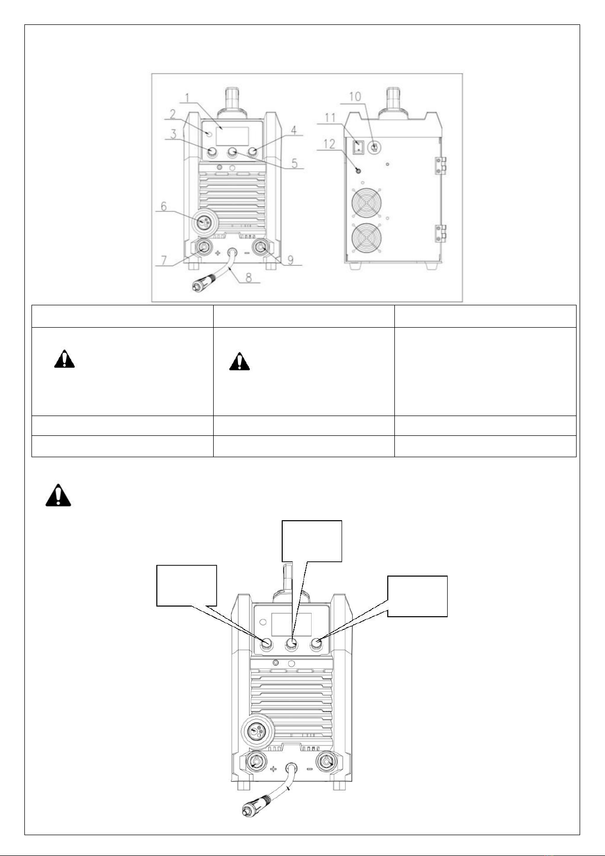
4.2. Welder’s Structures
HG200DP use the movable carton like structures: The upper part in the front is equipped with a welding current
regulation knob, power indicator light (green), abnormal indicator light (yellow), while the lower part is furnished with the
torch quick connector and “-” quick connector. The back side is installed with power switch, gas valve connection , cooling
fan, power source lead-in wire, breaker. On the top there is a handle for the convenient of easy transport.
4.3 Torch’s Construction
HG200DP, can weld alloy steel , aluminum silicon, aluminum magnesium alloy and carbon steel. For these welding wires
of different materials and different hardness, we consider more for the user when choosing the welding gun.
1. When welding for aluminum and aluminum alloy, include Al-Si, Al-Mg.
Please use the most original setting of the welding torch. The welding torch has a plastic wire feed tube.
Its advantage is smoother. It will not cause damage to aluminum welding wire and its alloy welding wire.
At the same time, you must ensure that the wire feeder roller is U-shaped!
2. When welding for stainless steel and carbon steel, include Fe, CrNi
Please replace the wire feeding hose of the welding torch with a metal spring tube. Since the stainless steel
and solid welding wire are too hard, it will cause damage to the plastic hose, it must be replaced. At the
same time, please note that replacing the wire feeder roller is V-shape.
Please note: It’s important for your welding

6
4.4 Sign & Pictures Illustration
DP MIG: Double pulse MIG
P MIG: Single pulse MIG
MIG: DC usual MIG
MMA : Arc welding
Aluminum wire and 100% argon gas
Aluminum Silicon and 100% argon gas
Aluminum Magnesium and 100% argon gas
Carbon steel and 100% CO2 gas
Carbon steel and 80% argon gas
Stainless steel and 98% Argon gas.
Inductance Control
Pulse wave and pre-post gas setting
Wire diameter selection
Wire feeding method
Special 2T/4T, include arcing starting and ending current, working time.
Single phases AC power source
Single phase stillness transducer--- transformer---rectifier
DC current
Inductance control(soft or hard)
Wire feeding speed and current(synergic matching)

7
5. INSTALLTION
5.1. Welder’s Placement.
* The dust, acid and erosible dirt in the air at the job site can not exceed the amount required by the norm.
* The welder must be installed in the place where it can not be exposed to sun and rain. Also it must be stored in less
humid place with the temperature range at -10~40°C.
* There should be 50 cm space about for the welding machine to have good ventilation.
* Apparatus to exclude wind and smoke should be equipped if the inside aeration is not sound
5.2. Connection between Welder and Power Source (See the Input Connection Sketch)
Connect the power source cable at the back board of the welder into the single phase 230 vlotage power network with
breaker; 380 voltage power sources is strictly prohibited to the welder which will severely damage the welder, otherwise
the user should take the consequences for it.
Power supply configure of a welder:
Notice: The melting current of the fuse is 1.2~1.5 times of its rated cur
5.3 The installation and connection of MIG Welding
Connection and installation of the wire feeder
1. When welding for aluminum and aluminum alloy, include Al-Si, Al-Mg
When welding aluminum and other soft materials, the hose inside the welding wire liner is a plastic hose and its
length can reach the inside of the wire feeder directly, as shown in the figure.
Item
HG200DP
Circuit breaker(A)
≥40
Fuse(Rated current)
40
Knife Switch(A)
≥40
Power cord(mm
2)
≥3.0

8
2. When welding for stainless steel and carbon steel, include Fe, CrNi
When welding materials such as stainless steel and carbon steel the hard wire, the wire liner in the welding gun is a
metal spring tube, and it must be replaced with a metal tube which packed with metal spring tube.
* Select suitable wire according to welding technology. The wire diameter must be matched with drive roll, wire guide
pipe liner and contact tip.
* Open the lid of wire reel on the wire feeder put “Wire Coil” into “Wire Reel” on the wire feeder. Attention:
Wire end under the “Wire Reel”, opposite wire feeder.
* There is damping screw device in the “Wire Reel” (hex head screw will be seen when open the lid). Pull the wire
reel with hand when adjust. If resistance is over large, may adjust damping bolt: screw clockwise will enlarge the
value and vice versa.
* Lead wire into “Wire Guide Pipe” of wire feeder, align wire with roll groove through “Drive Roll”, re-lead “Socket
Tip” and press “Drive Roll”. (If more welding wire is needed, it will be done after switching on the power.)
3. For the welding torch of the workpiece and the machine, please refer to the figure below for the output cable
connection
5.4 The installation and connection of STICK welding
MMA connect workpiece and the machine, please refer to the figure below for the output cable connection.

9
6. OPERATOIN
1. LCD Color screen
2. Homepage
3. Current adjustment
4. Inductance control
Operate interface data,
press it will gave cursor,
rotating the knob will move
the cursor position
5. Voltage adjustment(only MIG)
When operate interface data,
rotating the knob will adjust
the value under the cursor.
6. Eu-torch connector
7. Positive pole
8. Air joint
9. Negative pole
10. Power cable
11. Power switch
12. Cooling fan
ATTENTION : The protection class of HG200DP Series Inverter MIG/STICK Welder is IP21S. It is forbidden
to put in a finger or insert a round bar less than 12.5 mm (metal bar in particular) into the welder. No
heavy force can be employed on the welder.
#2 KNOB
#1 KNOB
#3 KNOB

10
6.1 DP MIG welding steps
1 Select DP MIG function
Rotate the above No.3knob –the cursor to DP MIG position and press it.
Inductance select
Welding hard or soft
Output Current
Detailed setting:
Wire diameter select Pulse wave or pre-
Post gas
Wire feeding method
When 1ST time into DP MIG function,
knob of NO.#1 #2 #3 only have a simple
function, rotate #2 adjust for voltage,
rotate #3 adjust for inductance.
Press #3, will have cursor.
Rotate #2, could adjust data under
the cursor.

11
2 Select material and wire diameter, wire feeding method.
Press 3#knob, will have a cursor, when the cursor appears, only 3#2# can be operated, and the remaining knobs cannot
be operated. If need adjust for current and voltage, inductance, need press 3# again to cancel the cursor.
When without cursor, 1# knob adjust for current, 2#knob for voltage, 3# knob for inductance.
Material and gas recommend.
Al - Ar
AiSi –Ar
Almg –Ar
Fe –CO2(carbon steel)
Fe –Ar 82%(carbon steel)
CrNi –Ar 98%(stainless steel)
Wire diameter:
Al, AiSi, Almg 1.0~1.2mm
Fe, CrNi 0.8~1.0mm
3 Pulse wave adjustment
Rotate 3# to
, press 3# will going to pulse wave adjustment.
Rotate 3# for cursor, rotate 2# for data under the cursor.
-normal 2T/4T -S2T/S4T
Arcing starting
current and time
Arcing ending
current and time

12
6.2 P MIG welding steps
Same as DPMIG, rotate 3# knob to PMIG and press.
Welding voltage Welding wire
Material selection
P MIG
Currently function
Inductance select
Welding hard or soft
Output Current
Detailed setting:
Wire diameter select Pulse wave or pre-
Post gas
Wire feeding method
The operation mode of single-pulse MIG is the same as that of double-pulse MIG. Double-pulse or single- pulse welding
can be selected according to the characteristics of the material and the welding method.
The only difference between the single pulse and the double pulse is that the single pulse is an analog pulse, the double
pulse is the second pulse built on the analog pulse, which is adjustable, and the first pulse-the single pulse cannot be
adjusted.
PMIG WAVE –Because the analog pulse cannot be adjusted, the wire feed speed can only be adjusted, pre and post gas
time.

13
6.3 USUAL MIG welding steps
Press 3# knob for cursor, rotate 3# knob for position,rotate 2# knob for date adjust under the cursor.
When without cursor, 1# knob adjust for current, 2#knob for voltage, 3# knob for inductance.
Normal MIG have no pulse, only adjust for wire feeding speed, pre and post gas time.
6.4 MMA welding steps
Rotate 3# knob to MMA and press.
Then we will going to MMA operation interface.
MMA operation interface –Rotate 1# knob for current, Press 3# knob for cursor, rotate It for position, rotate 2#knob for
date under the cursor.

14
7. TROUBLE SHOOTING
No
Breakdown
Analysis
Solutions
1
Display overheat
Voltage is too high (≥15%)
Switch off power source; Check the
main supply; Restart welder when
power recovers to normal state.
Voltage is too low (≤15%)
Bad power ventilation lead
to over-heat protection
Improve the ventilation condition.
Circumstance temperature is too
high.
It will automatically recover when
the temperature low down.
Using over the rated duty-cycle.
It will automatically recover when
the temperature low down.
2
Wire feeding motor
don’t work
Potentiometer not in the proper
status
Change potentiometer
Nozzle is blocked up
Change nozzle
Feed roller is loosen
Firm the bolts
3
Cooling Fan not
working or turning
very slowly
Switch broken
Replace the switch
Fan broken
Replace or repair the fan
Wire broken or falling off
Check the connection
4
Arc is not stable and
splash is large
Too large contact tip makes the
current unsteady
Change the proper contact tip or
roller
Too thin power cable makes the
power astaticism
Change the power cable
Too low input voltage
Enhance the input voltage
Wire feeding resistance is too large
Clean or replace the liner and the
torch cable had better in the line
direction.
5
arc can’t be pilot
Earth cable break
Connect earth cable
Work piece has much greasy dirty or
rusty stain
Clean greasy dirty or rusty stain
6
No shielded gas
Torch is not connected well
Connect the torch again
Gas pipe is pressed or blocked up
Check gas system
Gas system rubber pipe break
Connect gas system and bind firmly
7
Couldn’t feeding wire
Material wire different with wire
liner and wire feeding roller.
Make sure Al or Al-Si, Al-Mg, must
change to plastic wire liner, use U
type roller.
CrNi and solid wire must change to
metal spring tube, use V type roller.
8
Spatter too much
Check for correct gas shielded
Change to correct one.

15
8. SEMI-AUTOMATIC WELDING SPECIFICATION TABLE
8.1 I-shaped butt welding specification table
8.2 Flat head T-shaped welding

16
8.3 Flat angle welded joint (thin plate)
8.4 Flat angle welded joint (thin plate)

17
9. TRANSPORT & STORAGE
* Users should keep the packing materials with the machine to keep well storage during the long transportation. If the
machine need transfer, the wooden case is required. The sign such as ‘Lift’ and ‘Free of rain’ should be labeled on the case.
* After the package has been opened, it is suggested to repack the product as per prior requirement for future storage and
transport. (Cleaning job is required before storage and you must seal the plastic bag in the box for storage.)
* The machines should be free from rain and snow during transportation and storage. Keep notice of the warning sign on
the packing box when load and unload. The warehouse should keep dry & ventilation and free from corrosive gas or dust.
The tolerable temperature ranges from﹣25~﹢55℃and the relative humidity can not be more than 90%.
Table of contents
Other Hyundai Welding System manuals
Popular Welding System manuals by other brands

Thermal Dynamics
Thermal Dynamics SL60 operating manual

SAF
SAF NERTABLOC TH 400 PW Safety instruction for use and maintenance

Soyer
Soyer BMK-16 W operating instructions

Thermal Arc
Thermal Arc Firepower FP-95 operating manual

Riland
Riland ARC 315GTS user manual

WELDTECH
WELDTECH WT180MP operating instructions