HYVA R Series User manual

NEW R-LINE REFUSE COLLECTION MICRO
LOADING, TRANSPORT & UNLOADING RCM10
RCM10

New R-Line Refuse Collection Micro
User Manual RCM10
2
Contents
1PREFACE ........................................................................................................................................................ 4
1.1 HOW TO USE THIS MANUAL...........................................................................................................................4
1.2 EXPLANATIONS ON IMPORTANT NOTES IN THIS MANUAL ..................................................................................4
2SAFETY RULES.............................................................................................................................................. 5
2.1 REGULATIONS AND PROHIBITIONS CONCERNING MACHINE TRANSPORTATION ...................................................5
2.2 PREPARATIONS FOR SAFE TRANSPORT.......................................................................................................... 5
2.3 CONTROL PANEL.......................................................................................................................................... 5
2.4 PREPARATIONS FOR SAFE USE .....................................................................................................................5
2.5 SAFETY MEASURES IN THE COURSE OF USE ..................................................................................................5
2.6 SAFETY MEASURES DURING MAINTENANCE,CLEANING AND INSPECTION .........................................................6
2.7 FILLING GARBAGE INTO THE RCM10 ............................................................................................................ 6
2.8 EXPLANATIONS ON SAFETY MARKS ...............................................................................................................7
2.9 PERSONNEL REQUISITES..............................................................................................................................8
3DESCRIPTION OF THE MACHINE AND TECHNICAL DATA .....................................................................10
3.1 GENERAL DESCRIPTION OF THE MACHINE....................................................................................................10
3.2 MACHINE COMPOSITION –MAIN UNITS........................................................................................................ 11
3.3 DESCRIPTION OF THE MAIN UNITS...............................................................................................................12
3.3.1 Vehicle frame...................................................................................................................................12
3.3.2 Subframe .........................................................................................................................................12
3.3.3 Container .........................................................................................................................................13
3.3.4 Rear door, referred to as the “Hatch” ............................................................................................... 14
3.3.5 Waste expulsion bulkhead, referred to as the “Plate” ......................................................................15
3.3.6 Compactingshovel...........................................................................................................................16
3.4 TECHNICAL CHARACTERISTICS ...................................................................................................................17
3.4.1 Technicaldata..................................................................................................................................17
3.4.2 Characteristics of the treated product ..............................................................................................17
3.4.3 Characteristics of the sound emissions (noise)................................................................................17
3.5 FUNCTIONING PRINCIPLE............................................................................................................................18
3.6 INTENDED USEAND UNINTENDED USE .........................................................................................................20
3.7 WORK AREA’S,COMMAND AREA’S AND DANGEROUS AREA’S..........................................................................21
3.7.1 Work areas and dangerous areas....................................................................................................22
3.8 SAFETY DEVICES.......................................................................................................................................23
3.9 PERSONAL PROTECTIVE EQUIPMENT...........................................................................................................24
3.10 INDICATOR PLATES ON THE MACHINE...........................................................................................................25
3.11 DESCRIPTION OF THE COMMAND AND CONTROL EQUIPMENT.........................................................................26
3.11.1 Command panel inside the driving cab............................................................................................27
3.11.2 On-board button panel in the container loading/unloading zone (left side) ......................................28
3.11.3 Bin emptying commands and compactor commands.......................................................................29
4PROCEDURE TO START THE MACHINE ................................................................................................... 30
4.1 ENGAGINGTHE PTO.................................................................................................................................. 31
4.2 BIN EMPTYING...........................................................................................................................................32
4.3 WASTECOMPACTING..................................................................................................................................34
4.4 COLLECTIONTANKEMPTYING......................................................................................................................35
4.5 LEACHATEDISCHARGEMANOEUVRE............................................................................................................37
4.6 DESCRIPTION OF THE FUNCTIONING MODES ................................................................................................38
4.7 DESCRIPTION OF THE STOPAND RESET MODES ........................................................................................... 39
4.8 GENERAL SAFETY REGULATIONS REGARDING MAINTENANCE ........................................................................42
4.8.1 Regulations, precautions and prohibitions .......................................................................................43
4.9 RECURRENT MAINTENANCE –RECURRENT CHECKS.....................................................................................45
4.9.1 Safety devices: operating checks and signaling tools......................................................................46
4.9.2 Electrical system: operating checks and their functions...................................................................46

New R-Line Refuse Collection Micro
User Manual RCM10
3
4.9.3 Hydraulic and pneumatic systems: operating checks and their functions ........................................46
4.10 PREVENTIVE AND RECURRENT MAINTENANCE PROGRAMME.......................................................................... 47
4.11 LUBRICANTS..............................................................................................................................................52
4.12 MAINTENANCE OPERATING INSTRUCTIONS ..................................................................................................52
4.12.1 Clean the rear edge safety latch movement zone............................................................................53
4.12.2 Checking/topping up the hydraulic oil level...................................................................................... 54
4.12.3 Greasing the hinging and sliding points ...........................................................................................55
4.12.4 Changing the hydraulic oil................................................................................................................56
4.12.5 Replacing the unloading filter...........................................................................................................57
4.12.6 Storing the machine ......................................................................................................................... 58
4.13 SCRAPPINGAND DISPOSAL.........................................................................................................................59
4.13.1 Disposing of electric and electronic equipment................................................................................60
4.14 PROBLEMS AND SOLUTIONS –PRELIMINARY OPERATIONS.............................................................................61
4.14.1 Troubleshooting ...............................................................................................................................63
4.14.2 Positions of the sensors on the structure.........................................................................................66
5SERVICE SUPPORT .....................................................................................................................................67
6TECHNICAL PARAMETERS.........................................................................................................................68

New R-Line Refuse Collection Micro
User Manual RCM10
4
1 Preface
1.1 How to use this manual
This manual provides you with the necessary assistance for installing, operating and maintaining the RCM10. It
is recommended that you read this manual carefully so as to know the best way of using the RCM10. If the
operation methods in this manual are strictly followed and the equipment is maintained in a timely manner, it can
be used safely in the long run and potential malfunctions will be minimised.
If a system failure cannot be resolved using the methods provided in this Manual, please contact the distributor
or the manufacturer directly. Our wide service network will always be available to help you remove the
malfunction.
To guarantee the safety of the operators and avoid any damage to the system, it is essential to study the
instruction manual thoroughly before carrying out any operation on the machine.
1.2 Explanations on important notes in this manual
WARNING:
This symbol indicates the possibility of damage to the equipment and/or its components.
ATTENTION:
This symbol indicates accident-prevention regulations for the operators and/or any
persons at risk.
NOTE:
This symbol indicates useful information.

New R-Line Refuse Collection Micro
User Manual RCM10
5
2 Safety Rules
This chapter covers all the safety issues related to
the installation of the RCM10. In order to avoid
personal injury to the operator or (serious) damage
to the materials, please operate strictly following the
rules defined in this chapter.
Please provide this user manual, including all the
safety rules mentioned in it, to all staff involved in
the installation of the RCM10 and require them to
read carefully.
NOTE:
If anything is unclear about the
safety rules, please contact the
equipment manufacturer for proper
explanation.
2.1 Regulations and prohibitions concerning
machine transportation
Goods always travel at the buyer's risk as and from
delivery to the carrier. Transport is always to the
buyer's charge unless otherwise agreed at the time
of drawing up the contract.
The lifting of the machine, excepting via vehicle
lifts, is expressly forbidden without prior
consultation with HYVA.
The machine should always be transported by
driving or using suitable equipment built for
transporting motor-vehicles. The manufacturer
expressly forbids the lifting of the vehicle with
any type of system.
Following transportation, check the machine
has suffered no damage. In the event of
damage, it is forbidden to start up the machine.
Inform the authorised head immediately.
2.2 Preparations for safe transport
Check whether the connection between the
plug and the adapter is disconnected.
Check to ensure the cover plate/door of the
feed inlet is locked.
Check whether all the doors and valves are
locked tightly.
If a foldaway hook is used for your equipment, it
shall also be locked tightly.
Check whether the hook placed on the lifting
support for handling has been removed.
2.3 Control panel
There is an emergency stop button on the
control panel. In case of emergency, press this
button to stop all the moving parts immediately
(only superstructure).
A release button is provided on the master
control panel. In case of emergency, press this
button to retract the garbage compaction
mechanism back to its initial position. When
this button is released, the garbage
compaction mechanism will stop retracting.
Even when the emergency stop button has
been pressed or even when the door is in open
state, this function shall still be able to work
properly.
2.4 Preparations for safe use
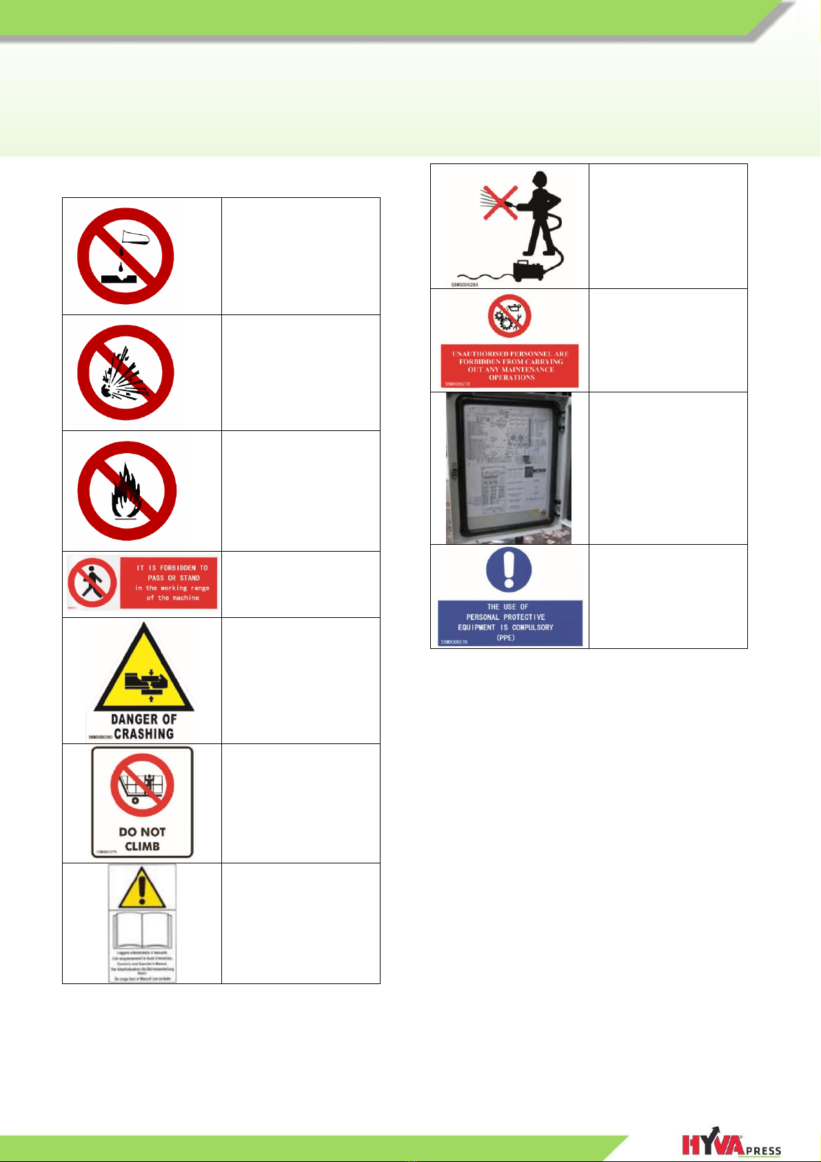
Do not remove any warning mark or plate from
the equipment. If the content on such warning
mark or plate becomes illegible, replace with
the same one immediately.
Make sure that all the staff operating the
equipment or conducting daily maintenance for
the equipment can find this user manual easily
for reference.
Make sure that the RCM10 is operated only by
the staff familiar with the performance of such
equipment. Such staff should know all the
knowledge concerning the equipment and get
familiar with the content of this user manual.
2.5 Safety measures in the course of use
In adverse weather conditions, please do not
use this RCM10.
During the course of operation, it is strictly
prohibited for any person to enter or step onto
the RCM10.
There should be no obstacle, which may affect
the operation or movement of the equipment,
around the RCM10.
Technical malfunctions may be very dangerous.
Therefore, in case of any such malfunctions,
contact the person in charge of installation
supervision immediately. The power supply to
the RCM10 must be cut off until the dangers are
removed,
It is strictly prohibited to put any flammable,
explosive articles or erosive chemicals and
other hazardous materials into the RCM10.
When any solid or fragile garbage (such as
glass or plastic) is processed with the

New R-Line Refuse Collection Micro
User Manual RCM10
6
equipment, there may be objects flying out of
the compaction chamber. It is recommended to
take some special measures wen processing
such garbage and your equipment supplier will
give you the relevant suggestions.
2.6 Safety measures during maintenance,
cleaning and inspection
The maintenance and repair work can only be
conducted by the authorized technical
personnel and only spare parts from the original
manufacturer shall be adopted for repair.
It is strictly prohibited to enter the compaction
chamber before the PTO/ENGINE supply is
stop. Firstly, please press the emergency button
and then press the release button. Please
follow this rule, otherwise personal injury or
even death may occur to the operator.
Before carrying out any maintenance work on
the RCM10, cut off the PTO/ENGINE supply
first. In order to avoid any person from
switching on the power supply accidentally,
please turn off the key of the engine.
2.7 Filling garbage into the RCM10
Elastic or spring force garbage shall not be
compacted in the RCM10 first or last. Similarly, in
order to avoid any problems when emptying the
container, massive homogeneous substances shall
not be simultaneously compacted using this RCM10.
In order to achieve best compaction effect,
massive elastic materials (such as thin metal
sheet or bed cushion etc.) shall be compacted
along with articles which are easy to be
compacted.

New R-Line Refuse Collection Micro
User Manual RCM10
7
2.8 Explanations on safety marks
It is prohibited to handle
or fill erosive
chemicals/garbage
It is prohibited to handle
or fill explosive
materials/garbage
It is prohibited to handle
or fill flammable
combustion
residues/garbage
It is forbidden to pass or
stand in the working
range of the machine
Residual risk of crushed
hands and feet.
DO NOT CLIMB
Warning! Consult the
instruction, use and
maintenance manual.
It is prohibited to use
high pressure spraying
for cleaning the control
panel
Unauthorised personnel
are forbidden from
carrying out any
maintenance
operations.
System code
identification plate
(inside the electric
panel)
The insertion of the strut
or safety pin, during
maintenance operations
with the collection
container raised, is
compulsory.

New R-Line Refuse Collection Micro
User Manual RCM10
8
2.9 Personnel requisites
Requisites for operators This manual refers to the following professional figures:
•
The operator responsible for managing the machine;
•
The machine maintenance technician.
•
The operators responsible for machine operation or maintenance must
possess the specific professional requisites for each operation
envisaged.
•
The operators must be instructed and fully aware of the duties
assigned to them, so they are made responsible for their own work.
Requisites for
personnel managing the
machine
Qualified personnel, able to carry out the following tasks:
•
Drive the vehicle by using the specific commands and the
remote push-button panel (when present);
•
Loading and unloading of the materials treated during the work;
•
Simple adjustment, start-up or reset operations following any
forced interruption.
Requisites for
specialised mechanical
maintenance
technicians
Qualified technician, able to drive the vehicle in normal conditions, operate it
with the protection devices deactivated, and intervene on the mechanical and
hydraulic elements to perform all necessary adjustments, maintenance and
repairs.
ATTENTION
The specialised mechanical maintenance technician is not
authorised to intervene on the electrical system in the presence
of an active voltage.
Requisites for
specialised electrical
maintenance
technicians
Qualified technician able to drive the vehicle in normal conditions and
operate it with the protection devices deactivated; responsible for all electrical
adjustments, maintenance and repairs.
Able to work when there is an active voltage inside the electric cabinets and
junction boxes.

New R-Line Refuse Collection Micro
User Manual RCM10
9

New R-Line Refuse Collection Micro
User Manual RCM10
10
3 Description of the machine and technical data
3.1 General description of the machine
Construction
characteristics
The machine manufactured by Hyva is a transformation of a vehicle with a
total minimum ground mass of 10000 kg and maximum of 12000 kg, with a
compacting tank mounted on its loading bed for compacting and transporting
municipal solid waste (subsequently referred to as MSW).
The transformation of the vehicle also includes a hydraulic control system for
emptying waste bins into the compactor.
Use The machine has been designed and manufactured to collect, compress and
transport municipal solid waste (MSW).
Capacity of the bins
that can be lifted by
the machine
•
Minimum capacity: 120 litres
•
Maximum capacity: 1100 litres
Characteristics of the
bins that can be lifted
by the machine
The machine can unload any type of bins, with a capacity ranging from 120
to 1100 litres, with the following types of connections:
CE plate, in Model field:
VD= DIN arm connectors for 660 to 1100 litre flat lid bins
VE= Europa arm connectors for 1100 litre bins
RV= Vertical rack connector for 120 to 1100 litre bins
RVP= Vertical rack connector for 120 to 1100 litre bins with
integrated door-to-door basket
VR= Rotary rack bin tip-up for 120 to 1100 litre bins
.
Prohibitions
ATTENTION
It is absolutely forbidden to use the machine with bins of a
different capacity from those specified in this manual, or with
different connections from those indicated above.
The incorrect anchoring of the bins can cause them to fall while
they are being emptied, thereby leading to the risk of injury.

New R-Line Refuse Collection Micro
User Manual RCM10
11
3.2 Machine composition –Main units
The main units that make up the machine are:
1) Vehicle frame;
2) Subframe;
3) Container;
4) Rear door, referred to as the “Hatch”;
5) Waste expulsion bulkhead, referred to as the “Plate”;
6) Compacting shovel.
Fig.2 - 1

New R-Line Refuse Collection Micro
User Manual RCM10
12
3.3 Description of the main units
3.3.1 Vehicle frame
Characteristics The machine is mounted on a vehicle frame with a load bearing capacity
ranging from approx. 10000kg, to a maximum of approx. 12000 kg.
ATTENTION
The vehicle frame can be of any make and model, as long as it is
approved with the laws in force in the country where it is
marketed.
3.3.2 Subframe
Preliminary remarks A subframe, which can be removed if necessary, is installed between the
vehicle's frame and the container bin, and is fastened to the frame in a
secure yet flexible manner in order to allow the vehicle's frame to bend freely.
Characteristics The subframe consists of longitudinal stringers made from pressed and
folded steel
Fig.2 - 2

New R-Line Refuse Collection Micro
User Manual RCM10
13
3.3.3 Container
Preliminary remarks The subframe supports a container made with framework, which has a
profiled rear section in order to give the entire unit a pleasing aesthetic
appeal.
Characteristics The container is made from sheet plates with reinforcement ribs at the
side. Some sheet metals are of high tensile wearable steel and corrosion
resistance material.
Fig.2 –3
Fig.2 –4

New R-Line Refuse Collection Micro
User Manual RCM10
14
3.3.4 Rear door, referred to as the “Hatch”
Preliminary remarks At the rear of the container, there is a closure door referred to as the
hatch, which contains the compacting shovel's slide guides.
Characteristics The hatch is opened by two hydraulic jacks during the unloading phase.
Both hydraulic jacks are equipped with stop valves to prevent the hatch from
closing in the event that the hydraulic hoses are broken.
In order to ensure the proper containment of any liquid waste, the structure
has been equipped with a gasket that makes contact with a specific edge on
the hatch itself.
The hatch can be locked using two cylindrical latches, which are manually-
operated on the KR version (Fig. 2 - 5).
Fig.2 - 5

New R-Line Refuse Collection Micro
User Manual RCM10
15
3.3.5 Waste expulsion bulkhead, referred to as the “Plate”
Preliminary remarks The container contains a waste expulsion plate, which consists of a rigid
inclined structure that moves on plastic slides with an extremely low friction
coefficient on a central guide (Fig. 2-6).
Characteristics This bulkhead is moved by a telescoping hydraulic jack.
Thanks to a dedicated hydraulic system, the bulkhead automatically retracts
during the compacting phase in order to allow the waste material to be
compacted as much as possible.
Fig.2 - 6

New R-Line Refuse Collection Micro
User Manual RCM10
16
3.3.6 Compactingshovel
Preliminary remarks The compacting shovel moves within special steel guides present in the
hatch.
Characteristics This shovel consists of a support carriage that moves within the dedicated
guides, which in turn is attached to a rotating "vane" that allows for the waste
material at the top of the container to be compacted.
The compacting operations are carried out hydraulically, and when the
container is full, a system of hydraulic valves prevents the shovel from
over-compacting the waste materials, thus safeguarding the integrity of all the
equipment.
Fig.2 - 10

New R-Line Refuse Collection Micro
User Manual RCM10
17
3.4 Technical characteristics
3.4.1 Technical data
NOTE
With regards the machine technical data, complete with measurements, weights, etc., refer to the
specific document enclosed with this documentation.
3.4.2 Characteristics of the treated product
Products allowed This machine is used to collect and compress municipal solid waste (MSW).
Products not allowed
ATTENTION
All the products not listed in the machine use section and in
paragraph 2.4.2 "Characteristics of the treated product" should
be considered not allowed, improper and therefore forbidden.
HYVA MECHANICS (CHINA) CO.,LTD. declines all liability for
injury to persons or damage to property resulting from the
failure to observe this warning.
3.4.3 Characteristics of the sound emissions (noise)
NOTE
The noise emission values at the operator's station are indicated in the CE facsimile of this manual,
in chapter 1.3.

New R-Line Refuse Collection Micro
User Manual RCM10
18
3.5 Functioning principle
Introduction The work cycle is described below, subdivided into the areas/phases of the
various work operations.
Sitting in the cab (1), the operator drives the vehicle
(Vehicle frame) to the container pick-up area.
The operator stops the vehicle (keeping the engine
switched on), then uses the commands in the cab
(figure “A” or “B”, based on the version supplied) to
engage the power take-off (via the couplings of the
gearbox) to activate the hydraulic circuit.
The operator engages the parking brake, exits the
cab, and goes to the container pick-up area.
The operator prepares the hook-up system based
on the type of bin to be picked up (figure “C”).
To be defined...

New R-Line Refuse Collection Micro
User Manual RCM10
19
Using the appropriate button (2), the operator
activates the compacting shovel (3).
NOTE Once the collection route has been
completed, the bin must be emptied. In
order to do this, use the buttons and
selectors on the control panel, which is
located either inside or outside the cab,
based on the version supplied.
This operation is performed by using the
appropriate button (7) to move the waste
expulsion plate. Once it has arrived at the
end of its stroke, the plate can be shaken
to eliminate any residues that have not yet
been expelled using the “shaker activation”
selector (8).

New R-Line Refuse Collection Micro
User Manual RCM10
20
3.6 Intended use and unintended use
Intended use This machine has been designed and manufactured to collect, compress and
transport municipal solid waste (MSW) within the limits specified in the
following sections:
•
Paragraph 2.1 "General description of the machine";
•
Paragraph 2.4.2 "Characteristics of the treated product";
•
The "specifications and technical data" document enclosed with
this manual.
Unintended use This machine must not be used for purposes other than those envisaged and
specified in the "Intended use" section.
Every other form of use differing from that for which the machine was
designed (and described in this manual) is considered "IMPROPER USE",
and Hyva declines all liability for any damage caused to persons, animals,
property, or to the machine itself.
ATTENTION
Any use other than that for which the machine was designed
may cause dangerous conditions for the operators/maintenance
technicians, any other persons exposed, and the machine itself.
Operators The manufacturer specifies the presence of only one operator to drive and
manage the machine.
ATTENTION
The presence of more than one operator to manage the machine
is unnecessary and inappropriate for safety reasons.
Permitted
environmental
conditions
This machine can be used in the street and in special waste disposal areas
Non-
permitted
environmental
conditions
This machine cannot be used in the following environments, where its
installation is strictly forbidden:
ATTENTION
Environments with potentially explosive atmospheres;
This manual suits for next models
1
Table of contents
Popular Industrial Equipment manuals by other brands

Bosch
Bosch ACS 653 Repair instruction

Reer
Reer FMC-B18 quick start guide

Chamberlain
Chamberlain K71-B1PH-1 quick start guide

PCB Piezotronics
PCB Piezotronics IMI SENSORS 080M470 Installation and operating manual

Cascade
Cascade TFC Raymond 4150 installation instructions

Loctite
Loctite CL15 UV Operation manual