ICAN July 2016 8
S W 1 2
K
E
SW13
K
E
SW4
K
E
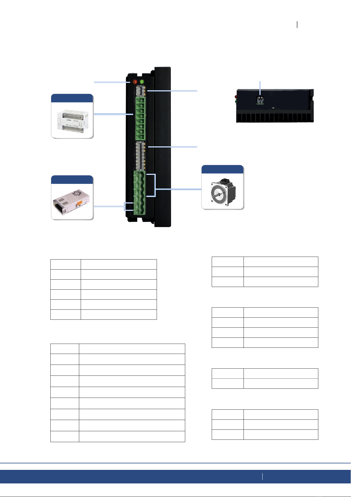
3-Phase Stepper Motor Drive 3MR8
■ Function setting
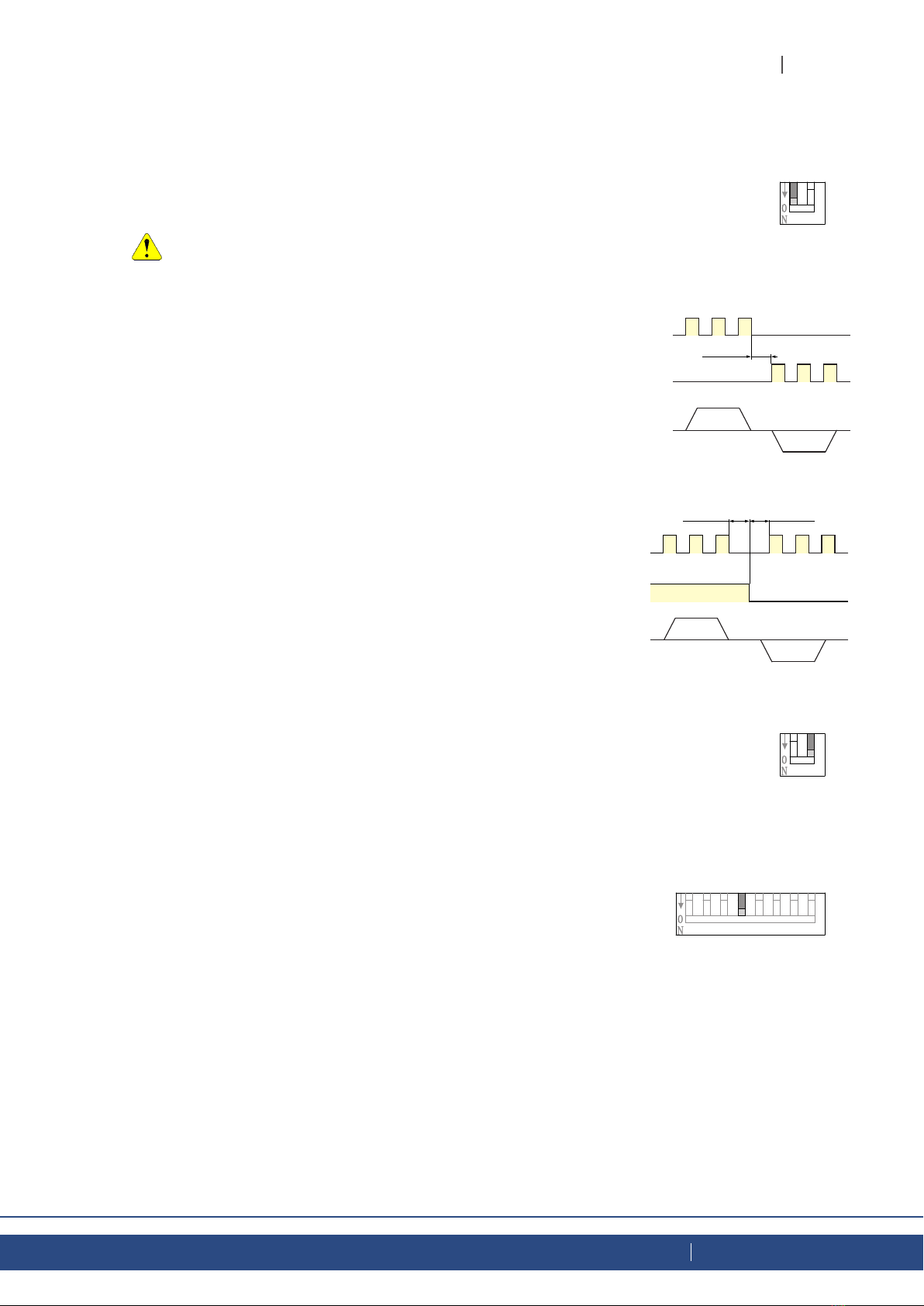
● Pulse Input Mode
CW/CCW mode: SW12=ON
PUL/DIR mode: SW12=OFF (factory setting)
The setting will take effect after recycle the power
CW/CCW Pulse
When pulse is input at PUL/CW terminal,
the motor will rotate by one step in one
direction.
When pulse is input at DIR/CWW terminal,
the motor will rotate by one step in the other
direction.
PUL/CW H
L
H
L
DIR/CWW
CW
CWW
Motor Motion
Above 2μs
Pulse & Direction
When pulse is input at PUL terminal, and DIR
terminal is high voltage, the motor will rotate
by one step in one direction. When pulse is
input at PUL terminal, and DIR terminal is low
voltage, the motor will rotate by one step in the
other direction.
H
L
H
L
CW
CWW
Above 2μsAbove 2μs
PUL input
DIR input
Motor Motion
Setting switch SW13 to ON after the drive is powered up will
cause the drive to perform a self test rotate the motor back and
forth, two turns in each direction, setting switch SW13to OFF
will disable this feature.
●Self Test
●
The running current of the motor driver is automatically reduced
whenever the motor hasn’t moved for 1 second. Setting the SW4
switch to ON reduces the current to 50% of its running value.
Setting this switch to OFF maintains 90% of the running current.
This 90% setting is useful when a high holding torque is required.
To minimize motor and drive heating it is highly recommended that
the idle current reduction feature be set to 50% unless the
application requires the higher setting.
Idle Current