I-Gard DSP-OHMNI User manual

C-EG30EM Instruction Manual V2, June 2020
DSP-OHMNI

2
I-Gard’s commitment to electrical safety provides both industrial and commercial
customers with the products needed to protect their electrical equipment and the
people that operate them.
As the only electrical-safety focused company whose product portfolio includes
neutral grounding resistors, high-resistance grounding systems and optical arc
mitigation, we take pride in our technologies that reduce the frequency and
impact of electrical hazards, such as arc flash and ground faults.
For those customers who have purchased from us over the last 30 years, you
know us for the quality and robustness of our products, our focus on customer
service and technical leadership. We build on this foundation by investing
in developing new products in electrical safety education - including EFC
scholarship program - by actively participating in the IEEE community programs
on technical and electrical safety standard, and working with local universities
at discovering new technologies. We remain unrelenting in our goal of improving
electrical safety in the workplace.
Our commitment to excellence is validated by long-standing relationships with
industry leaders in fields as diverse as petroleum and gas, hospitals, automotive,
data centers, food processing, aerospace, water and waste water plants, and
telecommunications. We provide our customers with the product and application
support required to ensure that their electrical distribution system is safe and reliable.
ABOUT I-GARD

1
SUBJECT
1. Introduction ..............................................................................................................................
2. Application ...............................................................................................................................
3. Installation ...............................................................................................................................
4. Wiring .......................................................................................................................................
5. Setup ........................................................................................................................................
6. Alarm Settings .........................................................................................................................
7. Operation ................................................................................................................................
8. Communications .....................................................................................................................
9. Specifications ..........................................................................................................................
10. Outline Dimensions .................................................................................................................
11. How To Videos .........................................................................................................................
TABLES
Table 1: DDR2 Types ....................................................................................................................
Table 2: System Module Requirements .......................................................................................
Table 3: Optional Modules ............................................................................................................
Table 4: Standard Ribbon Cables ................................................................................................
Table 5: Pulsing Frequency Selection ..........................................................................................
Table 6: Fault Message List .........................................................................................................
Table 7: List of Sensors for DSP-ADM ........................................................................................
Table 8: MODBUS RTU Standard 8 Byte Holding Register Read Function (o3) .......................
Table 9: Returned Information Structure for Holding Register Request ...................................
Table 10: Request to Write to Set a Bit on a Register (MODBUS Force Coil) ...........................
Table 11: Write Register Information .............................................................................................
Table 12: Returned Information from DSP Following a Force Bit Request ................................
Table 13: Feeder Module Ground Current Addresses .................................................................
Table 14: Feeder Module Status Addresses ................................................................................
Table 15: Feeder Module Priority Addresses ...............................................................................
Table 16: System Function Registers ...........................................................................................
FIGURES
Figure 1a: Typical One-Line Installation - Unit Substation .........................................................
Figure 1b: DSP-DCM Wiring ..........................................................................................................
Figure 1c: System Module DSP-DSM Wiring ...............................................................................
Figure 1d: Power Supply DSP-DPS Wiring ...................................................................................
Figure 2: Preferred Feeder Module DSP-DFM Wiring .................................................................
Figure 3: Alternative Sensor Wiring ...............................................................................................
Figure 4: Typical 4-wire Communications Connection ................................................................
Figure 5a: Alternative 2-wire connection for RS-485 ...................................................................
Figure 5b: TCP/IP Connection .......................................................................................................
Figure 6: Home Screen ..................................................................................................................
Figure 7: Alarm Screen ...................................................................................................................
Figure 8: Settings Page ..................................................................................................................
Figure 9: Password Settings Page ................................................................................................
Figure 10: Communications Set-up MODBUS TCP .....................................................................
Figure 11: Communications Set-up MODBUS RTU .....................................................................
Figure 12: Grounding Resistor Set-up ...........................................................................................
Figure 13: Feeder Module Status Page ........................................................................................
Figure 14: Feeder Module Selection, IDENT and Type Selection ...............................................
Figure 15: Feeder Module Set-up ..................................................................................................
TABLE OF CONTENTS
5
7
7
7
22
29
33
37
37
37
37
38
38
38
38
39
8
9
9
10
10
11
11
12
12
13
13
14
15
15
16
16
17
18
19
3
5
7
8
14
16
23
36
40
41
47

2
Figure 16: Feeder Module Successful ..........................................................................................
Figure 17: Pulse Settings Page .....................................................................................................
Figure 18: Typical Examples of Pulse Circuit Connection ..........................................................
Figure 19: Change of Date/Time Settings Warning ....................................................................
Figure 20: Date Settings Page ......................................................................................................
Figure 21: Normal Home Screen ..................................................................................................
Figure 22: System Leakage Current Ig ........................................................................................
Figure 23: Feeder Current Igf .......................................................................................................
Figure 24: Home Screen When In Feeder Fault ..........................................................................
Figure 25: Activate Pulsing from Pulse Settings Page ...............................................................
Figure 26: New Home Screen Indicates Pulsing ON ..................................................................
Figure 27: Alarm Screen ...............................................................................................................
Figure 28: Bus Fault ......................................................................................................................
Figure 29: Event Notification ........................................................................................................
Figure 30: Momentary Feeder Fault Example .............................................................................
Figure 31: NGR Measured OK ......................................................................................................
Figure 32: NGR Status Good Resistor .........................................................................................
Figure 33: NGR Fault .....................................................................................................................
Figure 34: DSP-DRM Not Connected ...........................................................................................
Figure 35: Arc Detection Module Status Page when no DSP-ADM is Present ..........................
Figure 36: Arc Detection Module Status Page with DSP-ADM Present and
No Alarms Active .........................................................................................................
Figure 37: Arc Detection Module Status Page With DSP-ADM Present and
Flash Alarm Shown on Channel ................................................................................
Figure 38: DIN Rail Mounted Modules .........................................................................................
Figure 39: DSP-DM Display Module with Cut-Out Detail ...........................................................
Figure 40: DSP-DPS Power Supply Connections ........................................................................
Figure 41: DSP-DPS System Module Connection .......................................................................
Figure 42: DSP-DFM Feeder Module Connection .......................................................................
Figure 44: DSP-DM Display Module Connections .......................................................................
Figure 45: Typical DSP-DRM Installation Connections ...............................................................
Figure 46: DSP-ADM Arc Detection Module Connections ..........................................................
20
21
22
22
23
24
24
25
25
26
27
28
28
29
31
31
32
32
34
35
35
41
42
42
43
43
44
45
46
46

3
1. INTRODUCTION
High resistance grounding (HRG) is becoming more prevalent in industrial and commercial electrical power
systems. As the need for reliable and stable power increases, the inconvenience of unwanted downtime in
processing, robotics and data service also become more critical and costly.
Single ground faults in motors and equipment are common and will cause interruption of service in solidly grounded
systems. HRG offers service continuity by limiting the ground fault current to a sustainable level for an indenite
time.
I-Gard’s DSP-OHMNI is an HRG system designed to provide service continuity using a Neutral Grounding Resistor,
a voltage alarm unit and a ground fault relay to detect the event of a single ground fault, signal an alarm condition
and display the affected phase and/or feeder using programmable voltage and current measurements.
The DSP-OHMNI system also allows the operator to identify the precise fault location using an integrated pulsing
module available in the OHMNI-PM or OHMNI-PM-RM resistor to modulate the current in the fault circuit which
can be detected using a portable clamp-on current probe (TS-SENSOR) connected to an ordinary ammeter (DMM)
meter. Thus, maintenance can be immediately alerted and an operator dispatched to locate the fault to isolate it
promptly.
In some applications, however, it is desirable to clear any fault on the system when it occurs with re prevention
or protection of sensitive equipment being the main concern rather than continuity of service. e.g. petro-chemical,
grain handling. In this case, in addition to fault indication, the DSP-OHMNI can be programmed to trip the breakers
associated with the fault with or without adjustable time delay (up to 99 hours). The alarm level is normally set at
50% (default) of the system maximum ground current, however with the DSP-OHMNI system other alarm levels
between 10% and 90% may be set as desired.
Additionally, the DSP-OHMNI has two TRIP modes. It can be set up to control circuit breakers to TRIP on the
occurrence of a single fault with or without time delay, or if the feeder circuit ground fault current exceeds 100A
on two (phase to ground to phase) faults (this can only occur when two faults exist since the current on a single
fault cannot exceed the grounding resistor rated current). The DSP-OHMNI can then be set-up to selective second
ground fault trip on a priority basis to protect the critical feeder. Because two circuits will be involved it is possible
to prioritize which circuit will be interrupted by a priority setting. This ensures that only the least important circuit is
interrupted.
The DSP-OHMNI system consists of a voltage sensor unit (DDR2), a Neutral Grounding Resistor (OHMNI-PM or
OHMNI-PM-RM) and a ground fault relay (DSP-DSYS) which includes a panel mounted display (DSP-DM) and
two 35mm DIN rail mounted modules (DSP-DPS & DSP-DSM) typically located inside the control compartment of
a switchgear. The modules are connected together using 20 pins-conductor standard ribbon cables. The panel-
mounted display module (DSP-TDM) is a Human Interface Device (HID) that allows set-up and control of the
system. Optional 35mm Din Rail mountable modules are available for specic applications.

4
Standard DSP-OHMNI Components:
- DDR2 voltage alarm unit
- OHMNI-PM or OHMNI-PM-RM resistor
- (DSP-DSYS)
- DSP-TDM (Touch Display Monitor)
- DSP-DPS Power Supply Module
- DSP-DSM Sytem Module
- DSP-DCM Communication Module
DSP-OHMNI Optional Modules (35 mm Din Rail):
- DSP-DRM Resistor Monitoring
- DSP-DFM Feeder Module
- DSP-ADM Arc Detection Module
- DSP-CA Cable Adaptor
- DSP-CAS Cable Adaptor with on/off switch
Standard DSP-OHMNI components
The DDR2 is a voltage alarm unit used for line-to-ground-voltage measurements of three phase power systems. The
DDR2 alarm unit may be used on wye connected resistance grounded systems or delta connected systems using an
articial neutral with a neutral grounding resistor.
The OHMNI-PM is a neutral grounding resistor used to limit the ground fault current to a safe level (typically 5A or
10A) for an indenite time. The resistor is available for 480V & 600V systems and can be equipped with optional
resistance monitoring components (sensing resistor & ZSCS) becoming an OHMNI-PM-RM. Both models includes
an integrated pulsing module to modulate the current in the fault circuit which can be detected by a portable clamp-on
current probe (TS-SENSOR) connected to an ordinary ammeter (DMM) meter.
The DSP-TDM is a panel-mounted display designed for ush mounting in a door. The DSP-TDM display indicates
faulted phase, total system leakage current, feeder branch current level and provides other information such as prior-
ity settings and resistor setting etc. It is used to set-up the system and provides manual control of the pulse location
system. The DSP-DM also provides MODBUS RTU communications through a RS-485 network and MODBUS TCP
communications through a Ethernet network to external information systems. The module includes a real-time clock
to signal the event time and date of each event captured (up to 1000 events). Events captured are loss of DDR-2
phase(s), bus fault, feeder fault, feeder trip and NGR fault for both trip-on-rst-fault, and trip-on-second- fault setups.
The DSP-TDM date stamps the events according to the time and date set up on the system set-up.
The DSP-DPS is a 35mm Din Rail mountable power supply module used to provide +5V, +12V and -12V regulated
power to all of the modules and also provides 10A, 240 VAC resistive Form C alarm relay contacts to operate a horn
or other means of alarm to alert the operator . The DSP-DPS operates on a wide range of AC input voltage supplies
from 100V to 240V AC without selection of any jumpers or switches and can also operate on a wide range of DC input
voltage supplies from 125V to 250V DC.
The DSP-DSM is a 35mm Din Rail mountable system module used to monitor the systems line-to-ground voltages
through the DDR2 voltage alarm unit. It determines if there is voltage unbalance in the system and the level of ground
fault current in the grounding resistor by measuring the voltage displacement of the neutral from ground, without any
connection to the neutral grounding resistor. It also signals phase indication to the DSP-TDM Display.
Optional DSP-OHMNI modules (35mm Din Rail mountable)
The DSP-DRM is the resistor monitoring module used to monitor the integrity of the neutral grounding resistor (NGR)
for change of resistance and/or open circuit condition. This module must be installed following the system module
(DSP-DSM) in the 35mm Din Rail line-up of the DSP-OHMNI system. The DSP-DRM uses external I-Gard zero se-
quence current sensors and a NGRS sensing resistor which provide voltage and current measurements of the neutral
grounding resistor to the (DSP-DSM). The DSP-DRM uses the same alarm system as the rest of the DSP-OHMNI
system.
The DSP-DFM is the feeder module which can be included in the DSP system to measure the fault current level in the
branch circuits that are protected. This module uses standard I-Gard zero sequence current sensors Type TxA or Rx-
yA. It is equipped with a Form C 10A output relay that can be used for breaker control. The DSP-DFM detects two fault
levels. Firstly, it detects the single fault, which creates a system alarm condition, and secondly through a priority level
system, it provides breaker
5
DANGER
2. APPLICATION
control to disconnect the least important circuit breaker in the event of a second fault occurrence providing continuity
of supply to the critical feeder. Through the setup of the DSP-DM Display, DSP-DFM is automatically set to the same
alarm level as that of the system module during feeder module set-up. This module should be mounted following the
DSP-DRM module in the 35mm Din Rail line-up.
Note: If the alarm level is changed in the system module (or the system module has been changed) then it may be
necessary to set-up the DSP-DFM modules afterwards.
The DSP-ADM is an arc detection module that uses air pressure and/or light sensing transducers to continuously
monitor up to 21 possible fault sources and offer a rst line of defense in the arc detection feature of the DSP-OHMNI
system. It is used to provide protection against arc ash hazards by lowering the incident energy level to safer values
protecting both, personnel and equipment, from severe damages. This module should be installed following the DSP-
DFMs in the 35mm Din Rail line-up.
The DSP-CA and DSP-CAS are cable adapter modules used when two or more DSP-OHMNI systems are connected
in double ended main-tie-main application. The DSP-CA and DSP-CAS are equipped with solid state switches to allow
connection only when the input terminals of one of these units are shorted (normally by a tie breaker contact) following
an outage of one of the power sources. The main breaker on the outage side will open and the tie breaker will close
(through key interlock or other controls) allowing power to be supplied from the ‘’live’’ side to the ‘’dead’’ side to main-
tain service and priority allocations to both DSP systems. These modules should be installed at the end of the 35mm
Din Rail line-up.
Communications is provided by Ethernet connection and a 4-wire RS-485 network connection from a jack located at
the side of the DSP-TDM display module. The communications protocol supported is MODBUS TCP and MODBUS
RTU, which is a master/slave system with selectable baud rates from 9600 to 256000 (default 57600). The DSP sup-
ports the MODBUS function read holding registers only, without exception support.
The DSP system is used in conjunction with I-Gard’s voltage sensor unit type DDR2. The DDR2 matches the DSP-
DSM input circuits to the system voltage. The DDR2 types available are catalogued as follows:
Part Description Certication
DDR2-1 Standard DDR2 for 120 V system
Recommended for applications on medium voltage systems, installed
on the secondary of three (3) “Y-Y” connected Voltage Transformers.
CSA & UL
DDR2-1-S01 Special 120V system with harmonic lter compatible with SIMGA and DRM CSA & UL
DDR2-2 Standard DDR2 for 240 Vs system CSA & UL
DDR2-2-S01 Special 183V system CSA & UL
DDR2-2-S06 Special 240V system with harmonic lter compatible with SIGMA & DRM CSA & UL
DDR2-2-S05 Special 288V System CSA & UL

6
DDR2-4 Standard DDR2 for 480 V system CSA & UL
DDR2-4-S01 Special 415V system CSA & UL
DDR2-4-SO2 Special 400V system CSA & UL
DDR2-4-SO3 Special 340V system CSA & UL
DDR2-4-SO4 Special 380V system CSA & UL
DDR2-4-S05 Special 400V system with harmonic lter CSA & UL
DDR2-4-SO6 Special 380V system with harmonic lter compatible with SIGMA & DRM CSA & UL
DDR2-4-SO7 Special 480V system with harmonic lter compatible with SIGMA & DRM CSA & UL
DDR2-6 Standard DDR2 for 600 V system CSA & UL
DDR2-6-S01 Special 525V system CSA & UL
DDR2-6-S03 Special 600V system with harmonic lter CSA & UL
DDR2-6-S06 Special 600V system with harmonic lter compatible with SIGMA & DRM CSA & UL
DDR2-6-SO2 Special 690V system
DDR2-6-S04 Special 690V system with harmonic lter
DDR2-6-S07 Special 690V system with harmonic lter compatible with SIGMA & DRM
The DDR2 provides output voltages VAG, VBG, VCG that are proportional to the phase to ground voltage and also
voltage VNG that is proportional to the neutral resistor voltage (i.e. total leakage/fault current of the system).
The OHMNI-PM is connected between ground and the neutral (star) point of the transformer on wye systems. On delta
systems an articial neutral device (I-Gard type DDAI) is required to provide a neutral (star point). Both OHMNI-PM
and DDAI devices are selected for appropriate current ‘let-through’, i.e.: the current, which will ow to ground, if there is
a direct short from line to ground (on any one phase).
Note: A good rule-of-thumb for resistor current selection is 1 ampere per 2000KVA, if no surge capacitors are on the
system, and 1 ampere per 1000KVA with surge capacitors.
DDAI and OHMNI-PM devices are available with UL Listing for continuous currents of 1 ampere to 10 amperes and up
to 600V for most systems. Other voltages and ratings are available upon request. For further information regarding the
use of these devices refer to:
Instruction Manual type DDAI Articial Neutrals
Instruction Manual type DDR2 Alarm Resistor Units
Instruction Manual type CA(S) Modules
C-430EM
C-440EM
C-415EM
Table 1: DDR2 Types

7
3. INSTALLATION
A typical installation will include for each power source (transformer/generator) 1 DSP-TDM, 1 DSP-DCM, 1 DSP-DPS,
1 DSP-DSM, 1 DSP-DRM and a number of DSP-DFM feeder modules as required with 1 for each branch protected.
Additionally there will be a DSP-OHMNI-PM pulsing resistor to ground the system. A voltage-sensing resistor DDR2 is
required for the DSP-DSM input, as well as one current sensor for each DSP-DFM for current detection. See Table 2
for typical requirements.
Catalogue Number Description Number Required/System
DSP-TDM Display Module 1 (part of DSP-DSYS/v2)
DSP-DCM Converter Module 1 (part of DSP-DSYS/v2)
DSP-DPS/v2 Power Supply 1 (part of DSP-DSYS/v2)
DSP-DSM/v2 System Voltage Module 1 (part of DSP-DSYS/v2)
OHMNI-PM Pulse Equipped Resistor 1
DDR2 Voltage Sensing Resistor 1
Table 3: Optional Modules
Catalogue Number Description Number Required /System
DDAI Articial Neutral Required only for delta system
DSP-DFM/v2 Feeder Module As required 1/circuit(feeder)
TxA or Rx-yA Toroidal Current Sensor 1/feeder module
DSP-ADM Arc Detection Module 1 required for arc detection application
DSP-CA Cable adapter module 1 required for Main-Tie-Main applications
DSP-CAS Cable adapter module (switch) 1 required for Main-Tie-Main applications
Table 4: Standard Ribbon Cables
Length Function Catalogue Number
5cm (2 in.) Module to Module connection RC-3
30cm (12 in.) Module to Module connection RC-30
DSP modules are mounted on a 35mm DIN rail generally located at the rear wall of a switchgear compartment. They
should be mounted side by side and connected with 20-conductor ribbon cable in a daisy chain conguration. This ap-
plies to the DSP-DPS, DSP-DSM and DSP-DFM modules only. DSP (outline dimensions). Care should be taken not to
over tighten the 8-32 nuts used to retain the DSP-TDM.
It will be necessary to provide a reliable power source (which is not interrupted by operation of the DSP output con-
tacts) for control power. The supply should be in the range of 120V to 240V AC, 50/60Hz or 125V DC up to 250V. The
control supply must be fused by a 1 ampere fuses as shown in Fig. 5 (Connection Diagram).
Table 2: System Module Requirements

8
4. WIRING
No. 14 or No. 16 switchboard wire is used for all current sensor, control and DDR2 connections, which need not be
shielded. 4-wire shielded cable should be used for the serial communications. A typical wiring schematic is shown in
Figure 1a. It is recommended to use twisted pair for wiring from the secondary of the zero sequence current sensors
(TxA) to the DSP-DFM.
Sensor wiring is not generally limited by length and may be up to a kilometer without degradation of performance,
since the sensor is a current source. Sensor wiring should be run in separate conduit from power wiring. The recom-
mended sensor wiring connections are shown in Figure 2, two twisted wires should be run from each sensor X1 and
X2 as indicated to prevent cross coupling between modules. If existing wiring does not allow this connection because
of common connection at X2 as has been common in some installations, then the G terminals of the DSP-DFM mod-
ules should be connected as shown in Figure 3.
Ribbon cables are available in different lengths as shown in Table 4. For other lengths contact I-Gard. The RC-cables
are used for module-to-module connections and are short in length. Note the orientation of the plug as marked on the
DSP-DM display module. If a second row of modules is installed on another DIN rail, the last module on the right can
be connected to the last module on the right on the second row using the RC-30 cable. Either slot can be used on the
DSP-DFM feeder modules for connection.
Figure 1a: Typical One-Line Installation - Unit Substation

9
Figure 1b: DSP-DCM Wiring
Figure 1c: System Module DSP-DSM Wiring

10
Figure 1d: Power Supply DSP-DPS Wiring
Figure 2: Preferred Feeder Module DSP-DFM Wiring

11
Note: For main-tie-main systems and multiple sources with tie breakers the priority buses can be joined together
with the use of I-Gard devices DSP-CA(S) and DSP-CA modules. The DSP-CA module converts ribbon cable to an
8-conductor shielded cable for this purpose. The DSP-CA(S) does the same thing except that it includes an electronic
switch to make or break the connections when the tie breakers are closed or open. The two modules are DIN rail
mounted similar to the other DSP modules in 70mm wide housing. See information on DSP-CA(S) in manual C-
415EM for typical wiring.
Figure 3: Alternative Sensor Wiring
Figure 4: Typical 4-wire Communications Connection
12
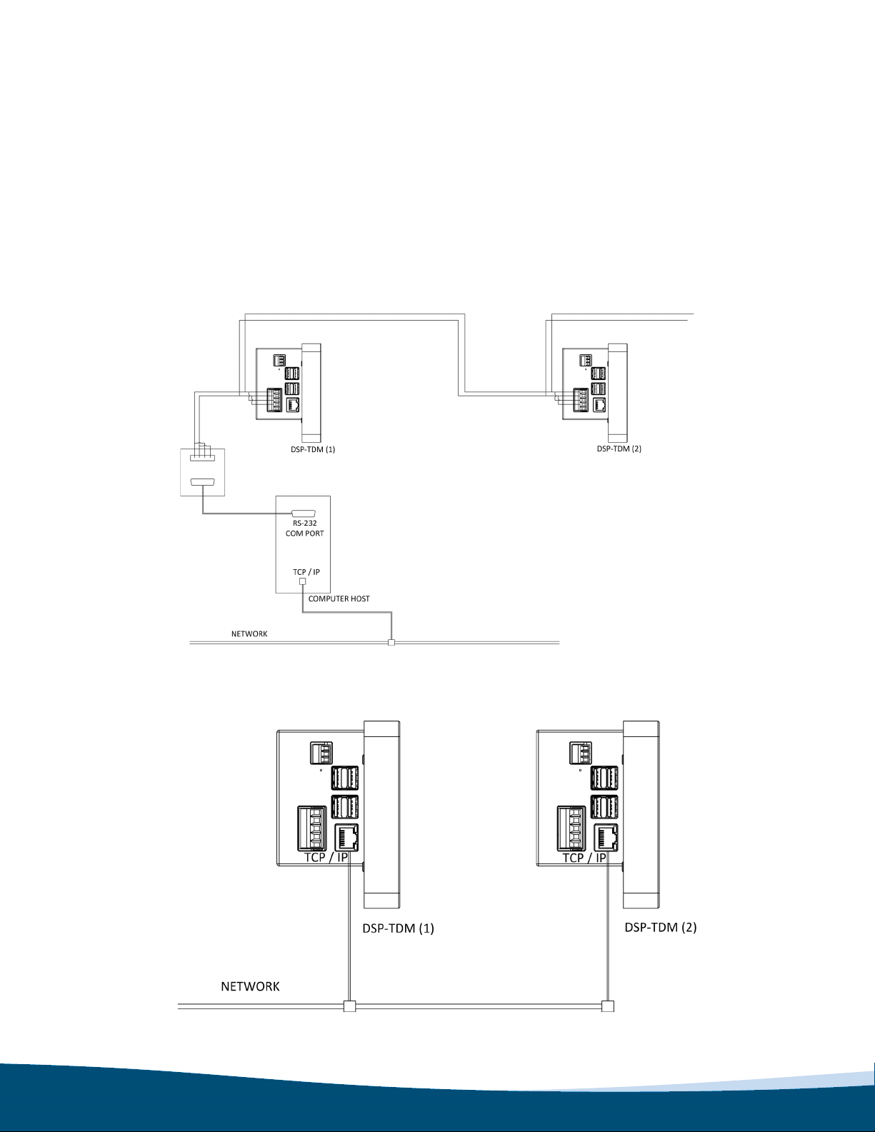
The RS-485 cable shield should be grounded at the ground terminal provided on the 5–pin jack as shown in Figure 4,
which shows a typical installation with a local computer and LAN.
Communications may be supported as a node in an existing MODBUS network or may be connected through a stan-
dard RS-485 to RS-232 converter to a PC with supporting software.
Note: the user must supply software to read the registers of the DSP-OHMNI system.
The alarm contacts are available at the DSP-DPS as a Form C type and should be connected to operate a horn or
other means to alert an operator to the fact that a fault has occurred on the HRG system. The contacts are rated at
10A, 240V AC resistive.
Figure 5a: Alternative 2-wire connection for RS-485
Figure 5b: TCP/IP Connection

13
Communications wiring may be 2-wire or 4-wire but must use shielded cable with low capacitance. Wire lengths up to
2000 meters can generally be used without the need for termination resistors. Figures 4, 5a and 5b show typical RS-
485 arrangements with a RS-485/RS-232 converter and a host PC connected to a LAN.
Pulsing Fault Location
For fault location the DSP system is equipped with pulse modulation for the ground current to locate the fault more
readily. Pulse current is provided at the DSP-DPS (+) and (-) terminals, which may be directly connected to the pulse
Relay in the DSP-OHMNI-PM. It is important to observe the polarity of the connection. This 12V wiring need not be
shielded but should be 14 or 16 AWG switchboard wire for durability.
Figure 6: Home Screen
This is the home screen, which is the NORMAL starting screen after RESET is pressed. Various messages may
modify this screen following an event such a phase fault, loss of fuse, or during pulsing to provide some diagnostic
information. If the following screen appears and the local alarm sounds, then the DDR2 resistor is likely not energized
or connected.
Figure 7: Alarm Screen
14
5. SETUP
Settings
On a new installation some simple set-up is required with at least maximum system current (NGR set-up) and feeder
modules being set prior to use of the equipment. Optional settings are communications and pulse control. On a new
installation some simple set-up is required with at least maximum system current (NGR set-up) and feeder modules
being set prior to use of the equipment. Optional settings are communications and pulse control. At the HOME screen
press SETTINGS to enter the settings screen.
This page gives access to make changes to system settings. Some settings sub-pages require Administrative permis-
sion to access.
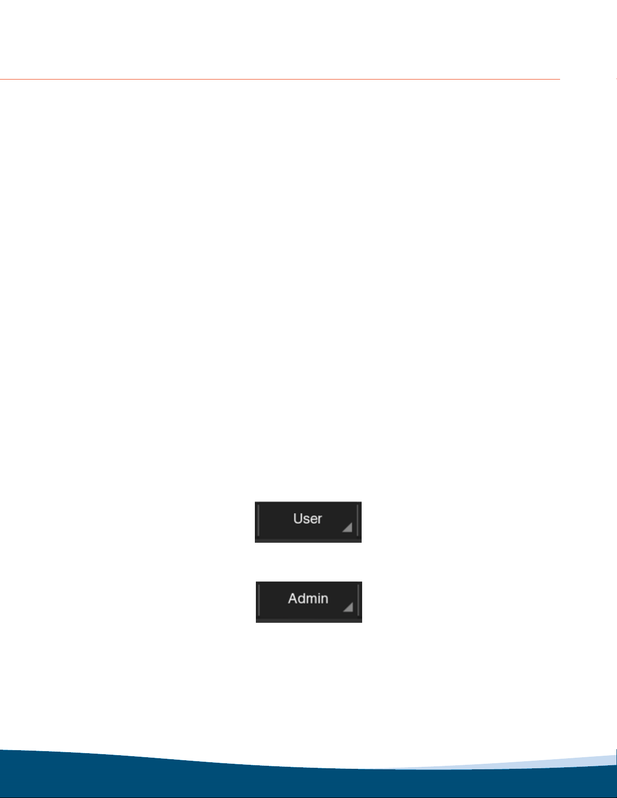
There are two modes of operation: Administrative and User. To have access to all the settings, it is necessary to log in
the Admin mode. To change between modes, just choose the mode on the drop box on the title:
or
When enter on the Admin mode, a password will be required. The default password is 8421, which will always be the
backdoor password, should the user password be forgotten. It is recommended to change this password.
Password
To change the password enter Admin mode, and from the HOME screen, press Settings ▸User Settings ▸Set pass-
word
Figure 8: Settings Page

15
Enter the new password and press Change Password. The password must be only numbers up to 8 characters. The
device will return to the User mode after save the data. It is possible to set a Password Hint to help to remember the
password in the future.
Communication
To change the communication settings, enter Admin mode, and from the HOME screen, press Settings, then press
Communication Settings
On this screen, you have the options to congure both MODBUS: RTU and TCP.
Figure 9: Password Settings Page
Figure 10: Communications Set-up MODBUS TCP

16
Figure 10 shows the rst set-up screen that will be encountered – COMMS set-up mode. The DSP-OHMNI is normally
shipped with a 57600 Baud setup.
The DSP system must be identied by an address number from 01 to 32, to distinguish between it and other MOD-
BUS devices that may be connected on the same MODBUS network. If only one device is used then it will typically be
set to 01, which is the default value (ensure that no other device has the same I/D setting on the MODBUS network or
data will not be valid). In order to change the number, select the eld and enter the desired number. Then, press Save
Device ID.
NGR & Alarm Settings
To change the NGR & Alarm Setttings enter in the Admin mode, and from the HOME screen, press Settings ▸NGR
and Alarm Settings.
6. ALARM SETTINGS
Figure 12: Grounding Resistor Set-up
Figure 11: Communications Set-up MODBUS RTU

17
This setting must be set according to the current limiting value of the grounding resistor of the HRG system. The de-
fault value is 1A. To change the number, select the value on the drop box. The nal value must be between 01 and 16
for 1-16A range.
Alarm Level Setting
The user may select from 10% to 90% of the neutral voltage displacement as a threshold in 10% increments.
The DSP-OHMNI is normally shipped with 50% level selected. Changing this value will require the user to setup the
feeder modules afterwards, since they are not automatically updated to the new alarm level. This will require Use of
the next setup procedure. If a new feeder module has been installed at a later date it will have to be setup also so that
the system is consistent.
GENERATOR mode should be used when the DSP is installed on a standby switchboard that provides control power
to the DSP so that it is always on and it is desired to suppress the “CHECK DDR2 FUSES” alarm that would normally
exist when the bus is de-energized.
Normally on the occurrence of an alarm when the MUTE button is pressed, the DSP-DPS general alarm relay (Form
C contact on terminals 27, 29, 31) is reset and the local annunciator is muted. This is the operation when the MUTE
ALARM setting is ENABLED. The default setting for the MUTE ALARM is ENABLED.
When the MUTE ALARM setting is DISABLED, then on the occurrence of an alarm when the MUTE button is pressed,
the DSP-DPS general alarm relay (Form C contact on terminals 27, 29, 31) is not reset but the local annunciator is
still muted. This setting is typically chosen when the general alarm relay is being monitored by a building automation
system, for instance.
After MUTE is pressed, the system will be MUTED until the Mute Delay Time is reached. Once reached, the system
will be UNMUTED.
Feeder Module Set-up
Figure 13: Feeder Module Status Page
To setup the Feeder Modules, enter Admin mode, and from the HOME screen, press Settings ▸FEEDER MODULE
SETTINGS.

18
Figure 14: Feeder Module Selection, IDENT and Type selection
After installation of feeder modules they must be given identication numbers from 01 to 50 (maximum) so that the
display unit can determine which module it is talking to. Each module must have a different number.
The display module is the master module and is constantly sending requests for data from each feeder module. The
feeder modules compare the request I/D with their own I/D to decide whether or not they are being asked for data. If
the I/D is the same, then that feeder module replies with current, priority and status information to the master display
module. Therefore it is very important that there are not two modules in the chain with the same I/D number after
setup.
In the case of 2 feeders with the same number, the user must enter a different I/D number before proceeding further.
The user is given the opportunity to enter a valid I/D number before the cursor moves to 2ND FLT/1ST FLT TRIP type
selection. This permits the TRIP and priority of previously set modules to be changed while retaining the same I/D
number. There will likely be duplicate I/D numbers prior to the rst setup and these will be overwritten by the set-up
procedure.
Note: If a duplicate I/D number has been selected, the ACCEPTED result could still be obtained
with the result that there will be two or more modules with the same I/D. If the FEEDER SELF TEST is
performed, these duplicates will not respond when the TEST button is pushed.
DANGER
Caution! It is possible for the user to enter a number outside the range 01 to 50 and the system will accept it without
warning, data will not be collected from such modules, although they will continue to provide fault protection.
Typically, the numbers will be in the sequence 01, 02, 03, 04…. but they can be in any order physically. The display
module does not discriminate the physical position of the modules in the chain.
Figure 13 shows the current feeder module congurations. Scroll to see all the feeders.
To change the Feeder Conguration, press Add/Remove Feeder Module.
Select the ID number to enter the set-up as follows:
Other manuals for DSP-OHMNI
1
Table of contents
Other I-Gard Protection Device manuals


Popular Protection Device manuals by other brands


Wasserstein
Wasserstein Screen Protector for Fitbit Sense 2 user manual

CD Automation
CD Automation Revo Revex 2PH Series user manual

Ultrasonic
Ultrasonic SonicPRO installation manual

Seg
Seg HighTECH Line MRI1IU instruction manual

Eaton
Eaton C Series Instruction leaflet

TEMPLAR
TEMPLAR GLOBBER 540-100 owner's manual

LPS
LPS AC Series installation instructions

ABB
ABB Relion REQ650 Product guide

ABB
ABB REL 551 2.3 Series Installation and Comissioning manual

nvent
nvent ERICO System 3000 Installation, operation and maintenance manual

GE Multilin
GE Multilin 850 Communications guide

Siemens
Siemens SENTRON 3VL160X System manual