I-Gard GCHK-100 User manual

Instruction Manual C-407
GROUND FAULT
PROTECTION SYSTEM
GCHK-100
GCHK-100
MINING RELAY
the power to protect

Each GCHK-100 relay and its auxiliary parts is carefully inspected before being packed for shipping. The unit
should be examined immediately upon receipt. If damage or indication of rough handling is apparent, I-Gard
should be notified promptly if replacements for damaged goods are necessary. If units received are not to be
installed immediately they should be stored in their original packaging in an area free of dust and moisture.
important
In our continuing effort to bring new and innovative products to the electrical
industry that provide additional safety and performance benefits,
I-Gard has developed a state of the art protection relay for mobile trailing
equipment.
Safety is enhanced by the addition of AC touch voltage protection, the only
relay in the market with this feature.
ground fault protection

GCHK-100 Instruction Manual I-GARD
1
taBle of contentS
1. Introduction 2
2. Catalog Numbers 3
3. Current Sensors 3
4. Pilot Wire Terminator 3
5. Remote Indication 4
6. Installation 5
7. Setup 7
8. Maintenance and Testing 11
9. Service 12
10. Specifications 13
11. Outline Dimensions 14
12. Instruction Manuals ibc
taBle of figureS
Figure 5.1 GCHK-DRI Label 4
Figure 5.2 mGARD-SYM Label 5
Figure 6.1 Connection Diagram 6
Figure 11.1 GCHK-100 Main Relay Outline Dimensions (inches) 14
Figure 11.2 mGARD-SYM LCD Remote Indicator Dimensions (inches) 15
Figure 11.3 GCHK-DRI LED Remote Indicator Dimensions (inches) 15
Figure 11.4 GCHK-ZT Zener Diode Line Terminator Outline Dimensions (inches) 16
taBleS
Table 2.1 Catalog Numbers 3
Table 7.1 Modes of Operation 7
Table 7.2 Ground Fault Pickup Settings 8
Table 7.3 Ground Fault Trip Delay Settings 9
Table 7.4 Ground Fault Delay Reset Intervals 9
Table 7.5 Ground Check Settings 10
Table 7.6 Frame Voltage Settings 11

I-GARD GCHK-100 Instruction Manual
2
1introduction
To service the special needs of the mining industry I-Gard developed the GCHK-100 ground fault relay to protect
personnel and equipment in underground or above ground applications.
The GCHK-100 is state of the art protection for mobile, trailing cable equipment, providing superior accuracy
and flexibility to the user. The micro controller based design reduces the likelihood of false tripping. The relay
automatically operates in three distinct modes:
•GroundFaultDetectionandcontrol
•Groundresistancecheckingandcontrolthroughtheuseofanauxiliarypilotwire
•Frametouchvoltagedetectionandcontrol
•ExternalremotedisplaywithModbus
Designed for use with resistance grounded systems up to 4160V. It could also be used with any Grounded
System in branch circuit applications.
The relay can also be used with an external remote indicator (mGARD-SYM), capable of remotely displaying
readings and allowing remote RESET and TEST. The mGARD-SYM can monitor up to 50 GCHK-100 relays and
provides an isolated connection to an external Modbus network. Alternatively, a standard LED based remote
indicator (GCHK-DRI) can be used for remote indication.
Ground Fault detection requires the use of current sensors, and the GCHK-100 is designed to operate with
I-Gard TxA type sensors or a wide variety of sensors with ratios of 1000:1, 600:1 and 40:1 (200:5). The sensors
are typically mounted in the substation where the GCHK-100 is installed. Detection of ground faults is important
to prevent arcing faults in equipment where electric shock and fire can occur and cause serious equipment and
personnel hazards.
Operator safety from electrical shock depends to a large extent on the integrity of the grounding of energized
equipment. Therefore, it is vital to know if grounding has been compromised. To do this an auxiliary conductor
(pilot wire) is used in trailing cable to mobile equipment. The GCHK-100 monitors the loop resistance and trips
when it exceeds a preset value.
Additionally the relay detects if the ground loop has been shorted as can happen when the trailing cable is cut
accidentally. For this purpose a pilot wire terminator is connected between the pilot wire and ground. I-Gard
provides a special zener package for this purpose (GCHK-ZT).
In the event of a ground connection failure and internal leakage within the mobile equipment, it is possible for the
frame of the equipment to become live and present a shock hazard to personnel in the vicinity. The GCHK-100
has the capability to monitor and control dangerous frame voltages.

GCHK-100 Instruction Manual I-GARD
3
2catalog numBerS
Table 2.1 indicates the product group for the GCHK-100 family from I-Gard
TABLE 2.1 CATALOG NUMBERS
Catalog Number Description No Required/System
GCHK-100 Mining Relay 1
GCHK-DRI LED Based remote indicator 1*
GCHK-ZT Ground Check zener terminator 1
mGARD-SYM Remote Indicator 1*
T series ZSCS current sensors 1
*EitherGCHK-DRIormGARD-SYMcanbeused(orbothifdesired),howeveritisnotnecessary;infact,the
GCHK-100canbeusedwithouteitherofthem.
3current SenSorS
Ground fault detection is achieved by the use of an external Zero Sequence Current Sensor (ZSCS). The relay
supports the following zero sequence current sensors or current transformers:
Any I-Gard T type sensors (e.g. T2A, T3A, T6A and T9A)
1000:1
10:0.0167 (600:1) Bender
200:5 (40:1) Startco
Surge protection is built into the relay; please refer to the electrical specifications data for withstand ratings.
ZSCS with, or without, built-in protection can be used with the GCHK-100 relay. The terminal block provides a
common ground and a terminal location for each of the three sensor types.
*NOTE: Only one type of ZSCS can be used at a time.
4pilot Wire terminator
This terminating diode is standard throughout the industry. It has two terminals marked GC and G. The GC
terminal is connected to the pilot wire inside the mobile equipment enclosure. The G terminal of the GCHK-ZT
is connected to the frame ground of the mobile equipment. The purpose of the diode is to allow the ground fault
relay to determine if the ground loop has been shorted. A shorted ground loop would appear as normal loop
impedance if this were allowed to happen, while in fact, the mobile equipment may be completely ungrounded.
Loss of zener voltage therefore causes the TRIP relay to operate and disconnect the power.
I-GARD GCHK-100 Instruction Manual
4
5remote indication
GHCK-DRI
A simple remote indicator is available as an option, which provides indication of the status of the GCHK-100.
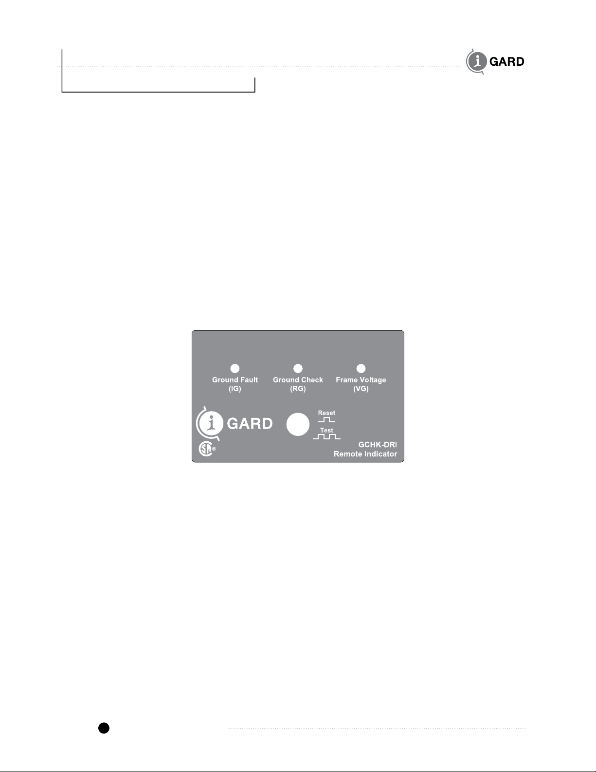
The GCHK-DRI has all three status lights that are normally visible on the GCHK-100 as well as a reset button.
This allows the relay to be monitored conveniently and RESET if necessary. The relay may also be tested by
pressing the RESET/TEST button twice quickly.
The GCHK-DRI is flush-mounted in a panel with four ½ in x 6-32 screws with nuts. A rectangular opening of 82 x
51 mm (3 1/4 x 2 in) is required for mounting as shown in Figure 11.3.
A 5-conductor cable with 22 gauge or larger conductors may be used to connect the GCHK-DRI to the
GCHK-100 relay. No shielding is required. No additional power supply is required to power the indicator.
Figure 5.1 shows the faceplate of the GCHK-DRI. This simple indicator extends the 3 red LED’s and yellow push
button on the GCHK-100 to a panel or remote location. Press the yellow button once to reset the relay or twice
quickly to test (Warning: a test will cause the GCHK-100 to trip).
Figure 5.1 GCHK-DRI label
mGARD-SYM
The mGARD-SYM is a remote display indicator that is used in conjunction with I-Gard Corp. relays. The
indicator has the capability to interconnect with up to 50 GCHK-100 relays in a bus network topology and
provides detailed device status information.
The display has a 4-line screen that shows a list of connected devices. A device can be selected and viewed in
detail. The relay mode, delay and trip level settings can be viewed (but not altered). The reset and test functions
can be performed directly from the display.
Fault levels are displayed as a percentage of the selected trip level. If the trip level is 1 Amp and there is a
500 mA fault current, the reading on the display will appear as 50%. Ground check resistance and frame voltage
are also displayed as a percentage of the trip setting. Screen navigation is done using a 4-button interface.
The menus are displayed on the right side of the LCD, the left side is reserved for viewing relay information.

GCHK-100 Instruction Manual I-GARD
5
mGARD-SYM
Power Alarm
Add%Ig %Rg %Vg
154 0
2100 0VIEW
300 5 SET
www.i-gard.com
the power to protect
Figure 5.2 mGARD-SYM label
The mGARD-SYM also provides an isolated connection to an external Modbus RTU network. All 50 devices
can be monitored remotely using a single configurable Modbus address. Built in isolation protects the Modbus
network from hazardous voltages or transients. The display is compatible with several Modbus speeds: 1200,
2400, 4800, 9600, 19200 and 38400 baud. Stop bits are selectable (1 or 2). Data available through Modbus
includes relay status and fault levels as well as remote reset.
For more information on the mGARD-SYM display refer to the mGARD-SYM manual (C-416EM-R0).
6inStallation
Mounting
The main unit of the GCHK-100 is supplied with a surface-mounting back-plate to provide simple 4-hole
mounting, compatible with existing units. If holes do not exist, drill 4 holes in the mounting location for
4 No. 6 self-tapping or sheet metal screws.
Remote Units
The remote indicators are intended for flush mounting in a visible place. They require cutout areas
in the mounting panels. See Dimensional Drawings for details.
Wiring (See Figure 6.1 Connection Diagram)
Control Power
Control power is required for the GCHK-100 relay. The power may be either AC or DC and between 100 and
250V. A source should be rated at least 5VA in capacity.

I-GARD GCHK-100 Instruction Manual
6
Control transformers may be connected to the LINE side of the protective breaker through protective fuses
or any other reliable source of power. Failsafe operation cannot be achieved with LOAD side connection
since the breaker would trip before the GCHK-100 had energized the TRIP relay thus preventing closure.
Furthermore, indication would be defeated when the breaker tripped and the power removed.
Current Sensors
There are no restrictions on the location of the ZSCS sensor, No.14 unshielded wire may be used to
connect the SEC terminals of the T type sensor to the 1000 Terminal and SENSOR ground as shown in
Figure 6.1 connection diagram. For other sensor types, the 600 or 40 Terminal would be used depending on
the ratio of the chosen sensor.
All phases supplied to the trailing cable must pass through the window of the ZSCS, which must be sized
accordingly. I-Gard sensors range from 2in. to 9in. in diameter. Neither the ground conductor, nor the pilot
ground conductors pass through the sensor; otherwise the ground fault detection would be disabled.
Figure6.1ConnectionDiagramshowstheShuntTripcoiloftheprotectivecircuitbreakerconnectedtotheNO
contacts of the GCHK-100 relay. This is the non-failsafe connection. The NC contacts of the Form Z relay are not
usedinthiscase,butwouldberequiredincaseoffailsafemodeofoperation.
GC G
GCHK-ZT
X0 X1
ZSCS
TRIPCOIL
UNIT SUBSTATION TRAILING CABLE
CONTROL POWER
5VA AC OR 5W DC
110-240VAC / DC
TO OTHER
GCHK-100
RELAYS
TO MODBUS
NETWORK
OPTIONAL
mGARD-SYM
INDICATOR
AUXILARY
RELAYS
OPTIONAL
GCHK-DRI
REMOTE
INDICATOR
GCHK-100
GROUND
CHECK
RELAY
MOBILE
EQUIPMENT
FAULT GND
RELAY CHECK

GCHK-100 Instruction Manual I-GARD
7
Ground Check
Ground Check is achieved by the use of a pilot wire (GC). This wire is usually a part of the power cable.
It is used to carry a monitoring current to the machine being monitored. The pilot wire must be properly
terminated at its end point (the machine being monitored). A zener diode terminator such as the GCHK-ZT
or equivalent is required.
The ground terminal must be connected to a reliable system ground. This provides a return path for the
current and completes the ground check loop. Ensure that all wires are firmly connected to eliminate adding
resistance to the system.
Frame Voltage
The Frame Voltage monitor is an additional feature that is monitored through the ground-check pilot wire.
No additional wiring is required for the Frame Voltage monitor.
7Setup
The GCHK-100 can be operated in different modes selectable with Switch 1. See Table 7.1
Normal mode is with a non-energized TRIP relay which becomes energized when the trip level is exceeded for
a duration exceeding the selected time delay. Alternatively, the FAILSAFE mode can be selected which allows
operation with an energized TRIP relay. This permits disconnection of the TRIP device in the event that power is
interrupted in the case (for example) of loss of a control fuse. Note for Failsafe operation, the control power must
be connected to a source that is not interrupted by the breaker trip operation.
TABLE 7.1 MODES OF OPERATION (SWITCH 1)
Function 1 2 3 4 5 6 7
Normal Mode 0
Failsafe Mode X
Normal Trip 0
Pulse Trip X
Manual Reset 0
Auto Reset X
Note:Xindicatesswitchison.
Note:Failsafeoperationdoesnotapplytotheauxiliaryrelays–onlytheTRIPrelay.
TRIP operation can be modified by use of Switch 1 position 2. When ON the contacts of the TRIP relay are
pulsed instead of continuous. This function reduces the duty cycle of TRIP coils which are not continuously
rated and do not have auxiliary contacts which open and remove the trip current.
I-GARD GCHK-100 Instruction Manual
8
For a ground check trip condition only, the GCHK-100 TRIP relay, and its auxiliary relay, may be automatically
reset upon the removal of the fault condition without operator intervention. Otherwise all relays are manually
reset by pressing the RESET push buttons on the relay or on the remote indicators.
Ground Fault
The GCHK-100 is set-up by DIP switches for different modes of operation and Trip Levels.
The ground fault pickup settings are set using switches 1, 2, 3, and 4 on DIP Switch 2.
The following pickup settings are available:
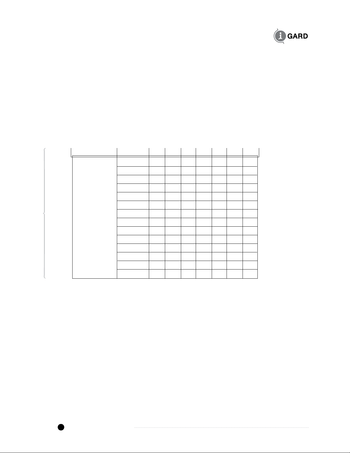
TABLE 7.2 GROUND FAULT PICKUP SETTINGS
Function Setting 1 2 3 4 5 6 7
Switch2 0.25A 0 0 0 0
Ground Fault 0.25 A 0 0 0 0
Pickup 0.5 A 0 0 0 X
Settings 0.75 A 0 0 X 0
IG 1 A 0 0 X X
1.25 A 0 X 0 0
1.5 A 0 X 0 X
2 A 0 X X 0
2.5 A 0 X X X
3 A X 0 0 0
5 A X 0 0 X
7.5 A X 0 X 0
10 A X 0 X X
12.5 A X X 0 0
Note:Xindicatesswitchison.
Pickup Setting Tolerance: -15% / + 0% (in accordance with UL, CSA and IEC requirements)
When a Ground Fault is detected, two relays are operated i.e. the main TRIP relay (Form Z)
and an auxiliary relay with form C contacts.
Ground Fault Trip Delay
Switches 5, 6, 7 on DIP Switch 2 are used to select the Ground Fault Trip Delay (See Table 7.3) This is the
interval between detecting a fault and tripping the relay. The delay will be cancelled if the fault clears before the
delay expires, thus preventing unnecessary trip operation.
GCHK-100 Instruction Manual I-GARD
9
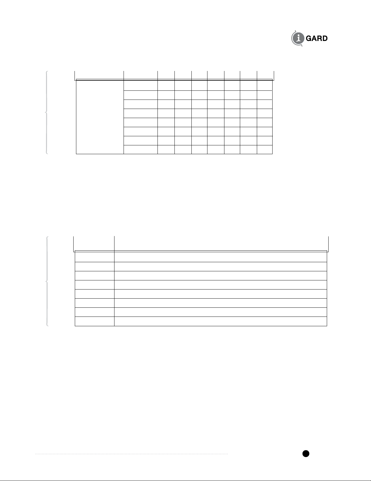
TABLE 7.3 GROUND FAULT TRIP DELAY SETTINGS
Function Setting 1 2 3 4 5 6 7
Switch2 0.02 s 0 0 0
Ground Fault 0.1 s 0 0 X
Delay 0.2 s 0 X 0
Settings 0.5 s 0 X X
1 s X 0 0
2 s X 0 X
5 s X X 0
10 s X X X
Note:Xindicatesswitchison.
Trip Delay Tolerance: -2 / +5 ms or ±2.5% of trip delay, whichever is greater
Once a Ground Fault is detected, the trip delay counter begins to time the trip interval. If the ground fault
disappears for the duration specified in the table below or more, the timer is reset and the relay does not trip.
TABLE 7.4 GROUND FAULT DELAY RESET INTERVALS
Trip Delay Clearance Interval (duration of time, fault-free, that is required to
prevent triggering a GF trip)
0.02 s Does not clear
0.1 s 18.3 ms
0.2 s 38.3 ms
0.5 s 98.3 ms
1 s 196.6 ms
2 s 398.3 ms
5 s 398.3 ms
10 s 398.3 ms
Ground Check
The ground check trip level can be adjusted using dipswitch 1, switches 4 and 5. Four resistance levels are
available as shown in Table 7.5
I-GARD GCHK-100 Instruction Manual
10
TABLE 7.5 GROUND CHECK SETTINGS
Function 1 2 3 4 5 6 7
10 Ohms 0 0
20 Ohms 0 X
30 Ohms X 0
*50 Ohms X X
Note:actual*levelincludestheimpedanceofthezenerdiodeaswellasthewireresistance.
Note:Xindicatesswitchison.
The TRIP relay will operate when the ground loop resistance exceeds the setting for a period exceeding 150 ms
to 300 ms. Also the RGindicator LED will light on the relay and remote indicators, if installed.
The current Ground Check resistance can be monitored using the mGARD-SYM remote indicator. The indicator
displays the ground resistance as a percentage of the current trip level. A Ground Check trip can be seen on
both the mGARD-SYM and on the GCHK-DRI (red LED will light).
Frame Voltage Operation
To provide a greater degree of operator protection, a voltage sensing function is included in the operation of the
GCHK-100 relay to detect if the frame to ground voltage of the mobile equipment has exceeded preset levels.
The voltage detection will operate within 100 ms (quicker than the ground check resistance detection) and within
30 ms if the frame voltage exceeds 100V AC. The intent is to provide a greater safety margin for the operator
and others in the vicinity of the equipment.
Frame Voltage can be monitored using the mGARD-SYM remote indicator. The indicator displays the Frame
Voltage as a percentage of the current trip level. A Frame Voltage trip can be seen on both the mGARD-SYM and
on the GCHK-DRI (red LED will light).
A flashing VGlight indicates a thermal overload, due to an elevated frame voltage (greater than 30 VAC, for
an extended period of time). The relay cannot be reset until it cools down to an acceptable internal operating
temperature.
Note: for higher frame voltages, the built in fuse may open prior to the thermal overload tripping. Replacement fuse type should be
BussFNQ-1⁄2orequivalent1⁄2Atimedelayfuse.
GCHK-100 Instruction Manual I-GARD
11
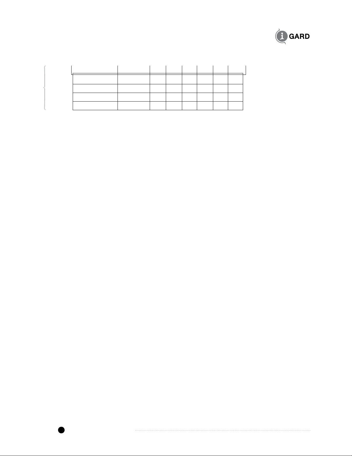
The frame voltage trip level can be adjusted to different levels as per Table 7.6 below
TABLE 7.6 FRAME VOLTAGE SETTINGS
Function 1 2 3 4 5 6 7
40V 0 0
60V 0 X
80V X 0
100V X X
Note:Xindicatesswitchison.
8maintenance and teSting
Due to the solid state design and the use of sealed components, it is not necessary to service the
GCHK-100 other than occasionally dusting with a damp cloth or vacuum cleaner during regular switchboard
maintenance.
DANGER
Hazard of Electrical Shock, Burn or Explosion
All installation, servicing and testing referred to in this manual must be performed by
qualified personnel. All power should be disconnected prior to removing covers or
enclosures and where live conductors may otherwise be exposed.
Failure to observe these precautions may result in death or severe personal injury
and damage to equipment
Before placing an intentional ground fault on the power system, check that a fault
does not already exist. Any test ground fault equipment must be rated for full
system voltage and interrupting capacity, and be fused for protection.
!

I-GARD GCHK-100 Instruction Manual
12
To test the GCHK-100 relay and remote indication, the RESET/TEST button is pressed twice quickly
in succession.
The relay will Trip and all red LED indicators will light on the Main Relay and Remote Indicator and hold
until RESET (by a single push of the RESET/TEST button). All relays will operate.
If annual inspection calls for more elaborate testing, this can be performed by primary injection of test current
through the window of the ZSCS and verifying that the pickup settings are within tolerance.
Testing should be done with a source of current, which is sinusoidal, has accurate metering and has a frequency
of 60 Hz.
Time delays may be measured with a digital storage oscilloscope. This can be done many ways but one way is
to apply a test “fault” resistor to the system with the oscilloscope connected to a current transformer arranged to
measure “fault” current. The Delay time will be the time that the current flows through the test “fault”. Note that
the resistor must be rated for continuous current at the rated voltage.
9Service
For assistance in installation, set-up or testing please call I-Gard toll free at the following number.
1-888-737-4787 (1-888-RESISTR)
There are no recommended, user-serviceable parts in the GCHK-100 other than replacement of the Pilot Wire
fuse. This fuse is a 600V rated 0.5A FNQ-½ by Bussman.
All other service should be referred to qualified factory representatives, other than direct replacement of entire
modules to I-Gard. Please visit the I-Gard website for information regarding field service representatives in your
area.
Note: Please ensure that proper authorisation is obtained from I-Gard before returning any material.

GCHK-100 Instruction Manual I-GARD
13
Control Power:
5VA AC or 5W DC
110-240 V AC/DC, 50/60 Hz
Maximum Range:
-45% to +10% (60-264 V AC/DC)
Temperature Range (Celsius):
Operating Temperature: -40 to +60
Storage Temperature: -40 to +80
Dielectric:
Relay contacts to chassis:
1480V rms. for 1 minute
Control terminals to chassis:
1480V rms. for 1 minute
Ground Fault:
Pickup Settings (Amps):
¼, ½, ¾, 1, 1¼, 1½, 2, 2½, 3, 5, 7½, 10, 12½
Pickup Tolerance:
–15%, +0%
Delay Settings (Sec.):
0.02, 0.1, 0.2, 0.5, 1, 2, 5, 10
Delay Tolerance:
–2, +5 ms or ±2.5% whichever is greater
Thermal Withstand:
5000 Amps for ¹/³seconds
Harmonic Filter:
Low pass analog filter
Zero Sequence Sensors:
Toroidal, with window diameter up to 225 mm.
Ratios supported:
Any I-Gard T type ZSCS (e.g. T2-A, T3-A, T6-A and T9-A)
1000:1, 600:1 and 40:1
(Input impedance 50, 50 and 1 ohm respectively.)
Ground Check:
Pickup Settings (Ohms):
10, 20, 30, 50 ohms
Pickup Tolerance:
±20% or 3 Ohms
Delay (for open loop and/or shorted terminator):
150 ms to 300 ms
Fuse (½ Amp, time-delay):
Bussman FNQ ½
LittelFuse FLQ ½
Edison MEQ ½
Operating Mode:
Manual Reset or Auto Reset
Induced AC Withstand:
30V Continuous (at 25°C ambient)
50V for 10 minutes (at 25°C ambient)
60V for 5 minutes (at 25°C ambient)
100V for 20s
Frame Voltage:
Pickup Settings (AC Volts rms.):
40, 60, 80, 100
Pickup Tolerance:
–15%, +0%
Delay (Sec.):
0.1 ±5% if voltage < 100 V AC.
Less than 0.03 if voltage ≥100 V AC.
Output Contacts:
Main Trip Relay:
Type: Form Z (NO and NC pair)
Rating:
10A @ 250V AC,
10A @ 30V DC,
½ HP @ 240V AC
Auxiliary Ground Fault Relay:
Type: 1 Form C (NO/NC)
Rating:
10A @ 240V AC,
8A @ 24V DC, ½ HP @ 240V AC
Auxiliary Ground Check Relay:
Type: 1 Form C (NO/NC)
Rating:
10A @ 240V AC,
8A @ 24V DC,
½ HP @ 240V AC
Terminal Contact Material:
Clamping screw: nickel-plated brass
Plug contacts: tin-plated bronze
Physical:
Weight: GCHK-100 855g
GCHK-DRI 45g
mGARD-SYM 600g
GCHK-ZT 35g
Dimension: See Figs. 11.1 to 11.4
Standards: CSA
I-Gard reserves the right to change specifications of its
products without notice.
10 SpecificationS
I-GARD GCHK-100 Instruction Manual
14
11 outline dimenSionS
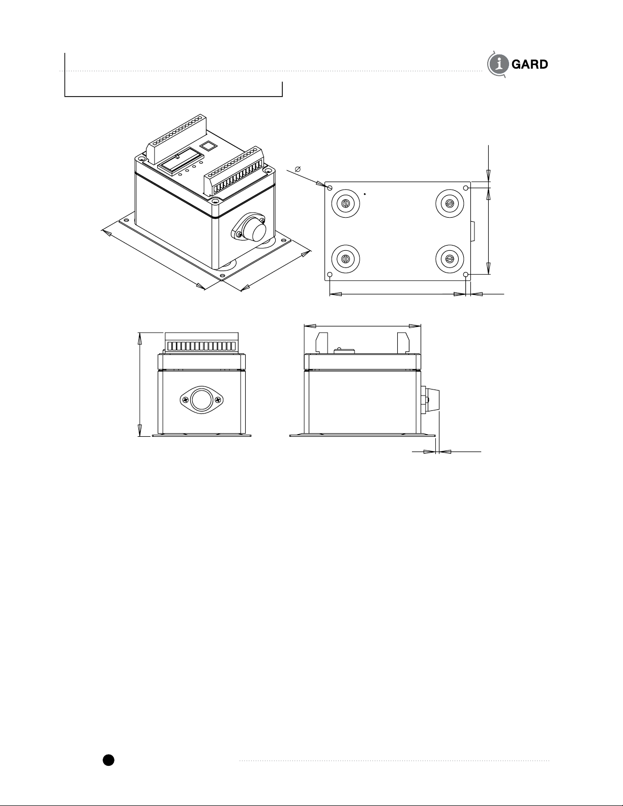
Figure 11.1 GCHK-100 Main Relay Outline Dimensions (inches)
5.50 0.20
0.253.50
0.19
4.20
5.90
4.00
0.15
4.72

GCHK-100 Instruction Manual I-GARD
15
Figure 11.2 mGARD-SYM LCD Remote Indicator Dimensions (inches)
5.16
5.16 2.15
3.94
3.94 0.41
3.94
3.94
0.41
Figure 11.3 GCHK-DRI LED Remote Indicator Dimensions (inches)
4.34
2.20
0.35
1.50
3.87
0.23
0.36
0.61
0.26
0.64
3.05
1.92
0.14
1.18
2.29
4.34
2.20
0.35
1.50
3.87
0.23
0.36
0.61
0.26
0.64
3.05
1.92
0.14
1.18
2.29
I-GARD GCHK-100 Instruction Manual
16
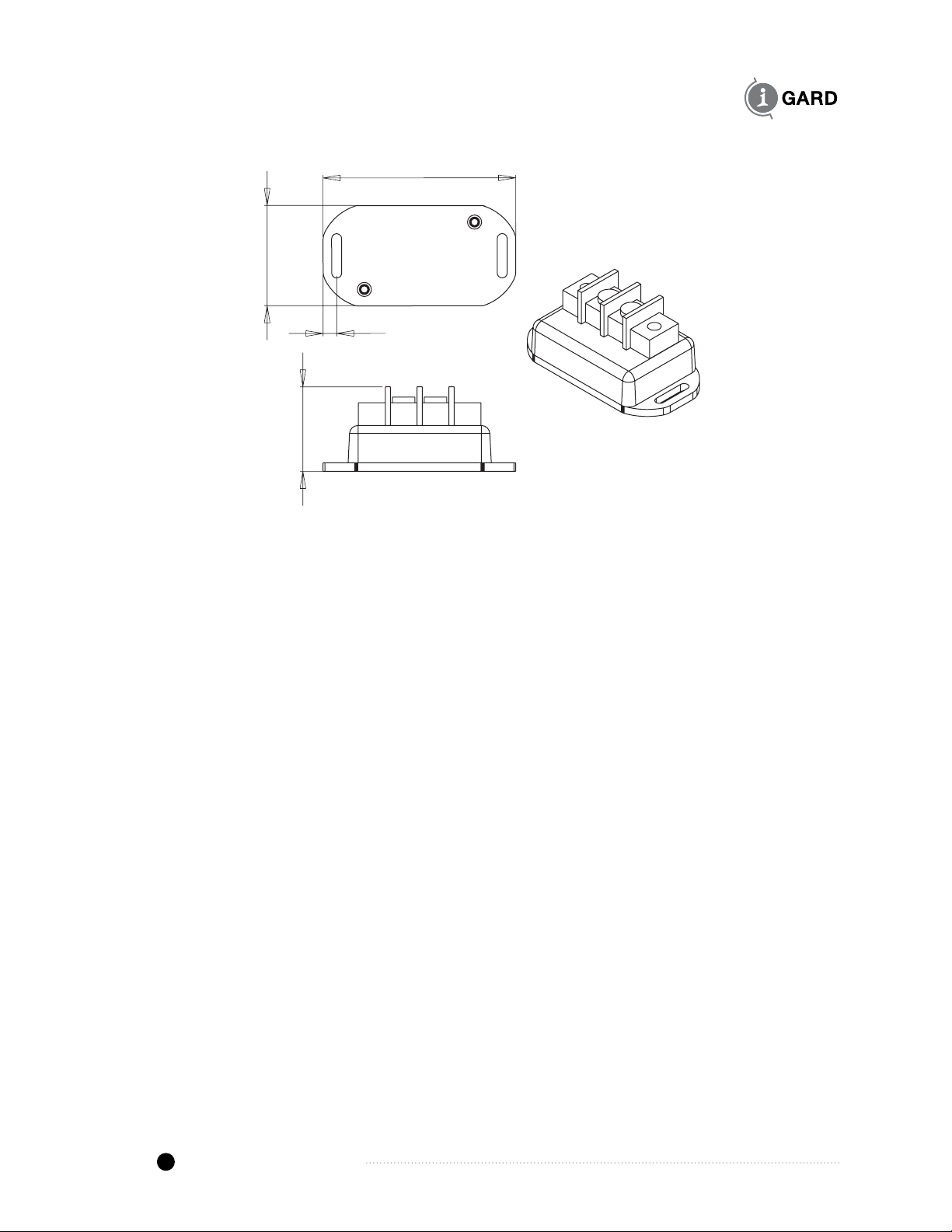
Figure 11.4 GCHK-ZT Zener Diode Line Terminator Outline Dimensions (inches)
1.16
2.65
1.38
0.19
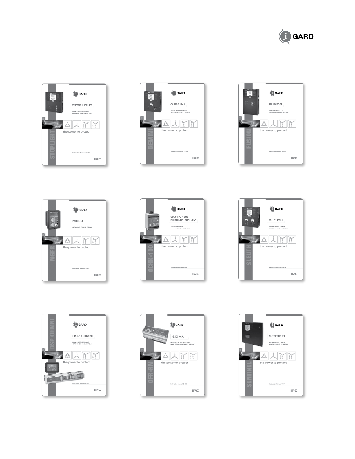
12 inStruction manualS
C-407 GCHK-100 Mining Relay
Ground Fault Protection
System Manual
C-408 Sleuth
High Resistance
Grounding System Manual
C-403 GFR-RM Sigma
Resistor Monitoring
and Ground Fault Relay
C-322 MGFR
Ground Fault Relay Manual
C-409 DSP Ohmni
High Resistance
Grounding System Manual
C-102 Gemini
High Resistance Grounding
System Manual
C-101 StopLight
High Resistance Grounding
System Manual
C-105 Fusion
Ground Fault Protection
System Manual
C-107 Sentinel
High Resistance
Grounding System
thepower to protect
Table of contents
Other I-Gard Protection Device manuals


Popular Protection Device manuals by other brands


Global Power Products
Global Power Products SURGE SAFE SM Series Installation, operation and maintenance manual

i4Technology
i4Technology BugHunter DAudio bda-4 Voice user manual

Kelley
Kelley AQUASHIELD SYSTEM AQS-900 Series installation instructions

Array Solutions
Array Solutions AS-309H Operation and installation

ABB
ABB RELION 650 SERIES Commissioning manual

Renkforce
Renkforce RS232 operating instructions


