manuals.online logo
Brands
  1. Home
  2. •
  3. Brands
  4. •
  5. American Innovations
  6. •
  7. Protection Device
  8. •
  9. American Innovations MicroMax GPS350 Instruction sheet

American Innovations MicroMax GPS350 Instruction sheet

© 2016-2018 American Innovations, Ltd.
The following procedures are general steps for a typical installation. For specific instructions, see the MicroMax
Interrupters User Guide (part no. 122204-000) available from your website account under the Help menu.
Installing the Equipment
Required Tools
Voltmeter Windows®Laptop PC
Bullhorn®Tools configuration software
USB to mini-USB cable
Optional Tools
(Continued)
MicroMax GPS350
Installation and Configuration
Part No. 122207-000, Rev. 1
1 of 4
Derating Table
Ambient Temperature Interruption Cycle
Celsius Fahrenheit 0.8 s ON - 0.2 s OFF 4 s ON - 1 s OFF
25 ⁰C
35 ⁰C
45 ⁰C
55 ⁰C
65 ⁰C 149 ⁰F
95 ⁰F
113 ⁰F
131 ⁰F
77 ⁰F 60 A
60 A
58 A
49 A
38 A 51 A
66 A
78 A
80 A
80 A
CAUTION: Metal relay casing on the MicroMax GPS350 will get hot. Allow 5 - 10 minutes after interruption
stops before handling the unit.
CAUTION: Do not connect the MicroMax GPS350 to primary mains power.
WARNING: Before beginning any wiring to the MicroMax GPS350, ensure that power has been turned off at
the rectifier.
GPS350 Installation & Configuration
Quick Reference Guide
MicroMax GPS350
Installation and Configuration
(Continued)
Quick Reference Guide
Part No. 122207-000, Rev. 1
2 of 4
MicroMax GPS350 Quick Reference Guide
January 2017
1To interrupt the AC power:
Connect Relay to Rectifier
GPS350 Relay
Connected to Rectifier
Positive Output
2To interrupt the DC power:
NOTE: These connections are not polarity sensitive.
b Slide shrink wrap tube
(provided) onto the second
MicroMax GPS350 relay
cable.
d Wrap assembly with
shrink wrap to prevent
equipment shorting.
GPS350 Relay Cable & DC
Output Cable
GPS350 Relay Cable & DC
Output Cable Wrapped
aRemove the tap change bar from the taps.
bConnect the two MicroMax GPS350 relay
wires to the taps.
NOTE: Connect relay wires to the same taps
that were connected by the change bar.
c Connect the MicroMax
GPS350 relay cable to the
DC output cable using
available hardware.
aDisconnect the DC output cable. Then connect one
of the MicroMax GPS350 relay cables to output.
GPS350 Relay Connected to
Rectifier AC
CAUTION: Do not connect the MicroMax GPS350 to primary power.
2
Locate Power Source for MicroMax GPS350
1Determine how to power the MicroMax GPS350 using one
of the following sources:
1
Tap Change Bar
aRectifier — with power turned on to the rectifier, use a
voltmeter to locate a power source across any two
available AC taps. The MicroMax GPS350 requires 8 - 42
V AC.
bA 120 V AC convenience outlet with the 12 V DC wall
adapter.
cA DC source, such as a 10 - 60 V DC battery.
2Turn off rectifier power.
POWER DEVICE WITH:
FINE/COARSE TAPS
8 V - 42 V AC
OR
12 V DC WALL ADAPTER
OR
BATTERY
10 V - 60 V DC
Part No. 122207-000, Rev. 1
(Continued)
MicroMax GPS350 Quick Reference Guide
3 of 4
© 2016-2017 American Innovations,
Power
GPS Antenna
Connection
Connect Power Cable
Connect GPS Antenna Cable to
MicroMax GPS350
3Connect red/white twisted wire cable to INPUT
connection on Power Cable. Then clip alligator clips
to rectifier AC taps. Voltage range is 8 - 42 V AC.
1Connect GPS antenna cable to
MicroMax GPS350 GPS Antenna
connection.
2Place GPS antenna outside of rectifier
in an area with a clear view of the sky.
1Connect Power Cable to
MicroMax GPS350 Power
connection.
GPS350 Power Connection
2OPTIONAL: If external relay is used, connect relay
control or coil to Power Cable OUTPUT. Be sure
to observe proper polarity, especially if a flyback
diode is present on a mercury relay coil.
Power Cable
OUTPUT
Alligator Clips
on Rectifier Taps
Power Cable
GPS Antenna GPS350 GPS
Antenna Connection
Twisted Wire Cable Connected to Power Cable
Power
GPS Antenna
Connection
4
3
WARNING: Ensure that the antenna connection does not come into contact with any conductive surface of the rectifier.
Part No. 122207-000, Rev. 1
January 2017
4 of 4
MicroMax GPS350 Quick Reference Guide
Program MicroMax GPS350
5
9Close and lock the clear cover on the MicroMax GPS350. Place interrupter inside the rectifier.
aPress to select interruption schedule - Daily,
Continuous, or Start/Stop.
bUse and to move through fields; use
keypad to change settings.
cPress to begin program.
to move through fields; useto move through fields; use
6 For Interruption, enter a number between 1 and 9
for the program number.
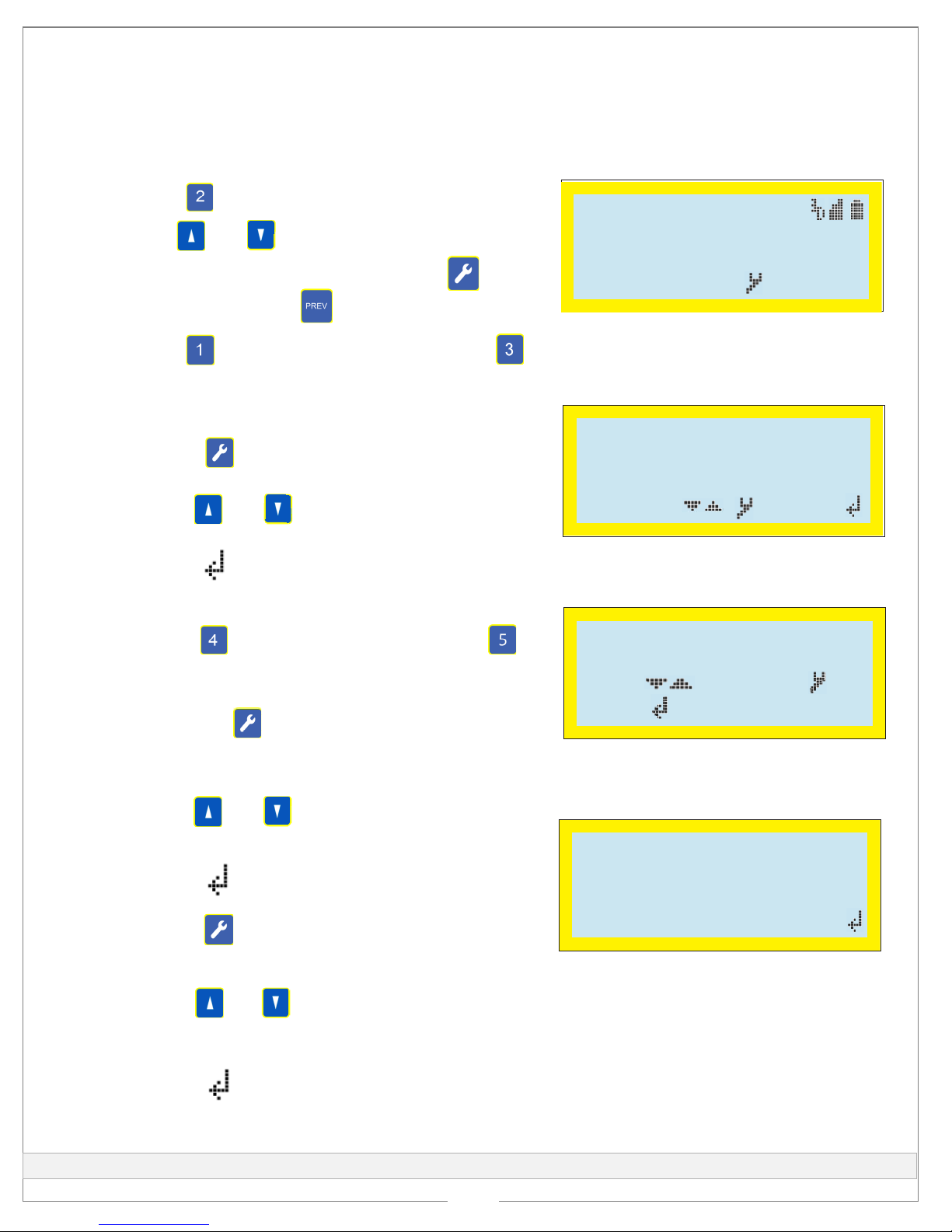
1Power on the rectifier.
2Press to view GPS information.
3Use and to change display contrast.
4OPTIONAL: From the main menu, press to
run Test Mode. Press to return to main menu.
5Press to set up an Interruption program OR
to set up an Interference program.
to change display contrast.to change display contrast.
Press to set up anPress to set up an
Press to view GPS information.Press to view GPS information.
MicroMax GPS350 Main Menu
12:01:03 02/25
1:Interrupt 2:GPS
3:Interference
4:Options :Test
Interruption Program
# 5 On 12.0 Off 03.0
Start 06:00 01/01/14
Stop 18:00 12/31/99
Change: / Set:
Change: / Set:
#10 On 13.0 Off 05.0
Delay 002.0
Cycle Time 0088s
Unit #07/10 Next:
Interference Program
8For Interference:
aUse and to move through fields. Use
keypad to change settings.
bPress to select type of interruption.
cPress to select interruption schedule - Daily,
Continuous, or Start/Stop.
dUse and to move through fields. Use
keypad to change settings.
ePress to begin program.
to move through fields. Useto move through fields. Use
aPress to access a list of Options and then
to view or edit Switch and Int. Cycle options.
bTo change settings, move the cursor to the option
and press .
7 For Interruption Output Parameters:
To change settings, move the cursor to the optionTo change settings, move the cursor to the option
and press .and press .
Switch: Norm Closed
Int. Cycle: ON/OFF
Move: Change:
Done: Cancel:PREV
Done: Cancel:PREV
Move: Change:
Move: Change:
Move: Change:
Done: Cancel:PREV
Done: Cancel:PREV
Out Parameters
The following procedures are general steps for programming the GPS350 using the unit keypad. For instructions
on programming the unit with Bullhorn Tools, refer to the online help available from the Bullhorn Tools Help
menu or to the MicroMax Interrupters User Guide.

Other American Innovations Protection Device manuals

American Innovations SurgeProtect Kit User manual

American Innovations

American Innovations SurgeProtect Kit User manual

American Innovations Lightning Arrester Surge Kit User manual

American Innovations

American Innovations Lightning Arrester Surge Kit User manual

Popular Protection Device manuals by other brands

COMPERE KPM83MD user manual

COMPERE

COMPERE KPM83MD user manual

Miller 216WLS User instruction manual

Miller

Miller 216WLS User instruction manual

Renson Topfix Max manual

Renson

Renson Topfix Max manual

Superfire EP5 Sonic Defenders Max manual

Superfire

Superfire EP5 Sonic Defenders Max manual

EMC Data Domain DD9500 Field Replacement Guide

EMC

EMC Data Domain DD9500 Field Replacement Guide

Siemens SIPROTEC 7SS52 Operation manual

Siemens

Siemens SIPROTEC 7SS52 Operation manual

LNTECH SLA-3 instruction manual

LNTECH

LNTECH SLA-3 instruction manual

Protekt P-30 instruction manual

Protekt

Protekt P-30 instruction manual

Warmup NAMSRK-6FT quick start guide

Warmup

Warmup NAMSRK-6FT quick start guide

hager BD163T User instructions

hager

hager BD163T User instructions

ABB ret650 Applications manual

ABB

ABB ret650 Applications manual

Arcteq Generator Commander instruction manual

Arcteq

Arcteq Generator Commander instruction manual

ABB Relion REG650 Commissioning manual

ABB

ABB Relion REG650 Commissioning manual

Franklin Electric submonitor Installation & operation manual

Franklin Electric

Franklin Electric submonitor Installation & operation manual

ABB FPTC-02 user manual

ABB

ABB FPTC-02 user manual

Ducati 96767609B manual

Ducati

Ducati 96767609B manual

ESAB Origo Air User instruction manual

ESAB

ESAB Origo Air User instruction manual

OBO Bettermann PDP-2-48-D Mounting instructions

OBO Bettermann

OBO Bettermann PDP-2-48-D Mounting instructions

manuals.online logo
manuals.online logoBrands
  • About & Mission
  • Contact us
  • Privacy Policy
  • Terms and Conditions

Copyright 2025 Manuals.Online. All Rights Reserved.