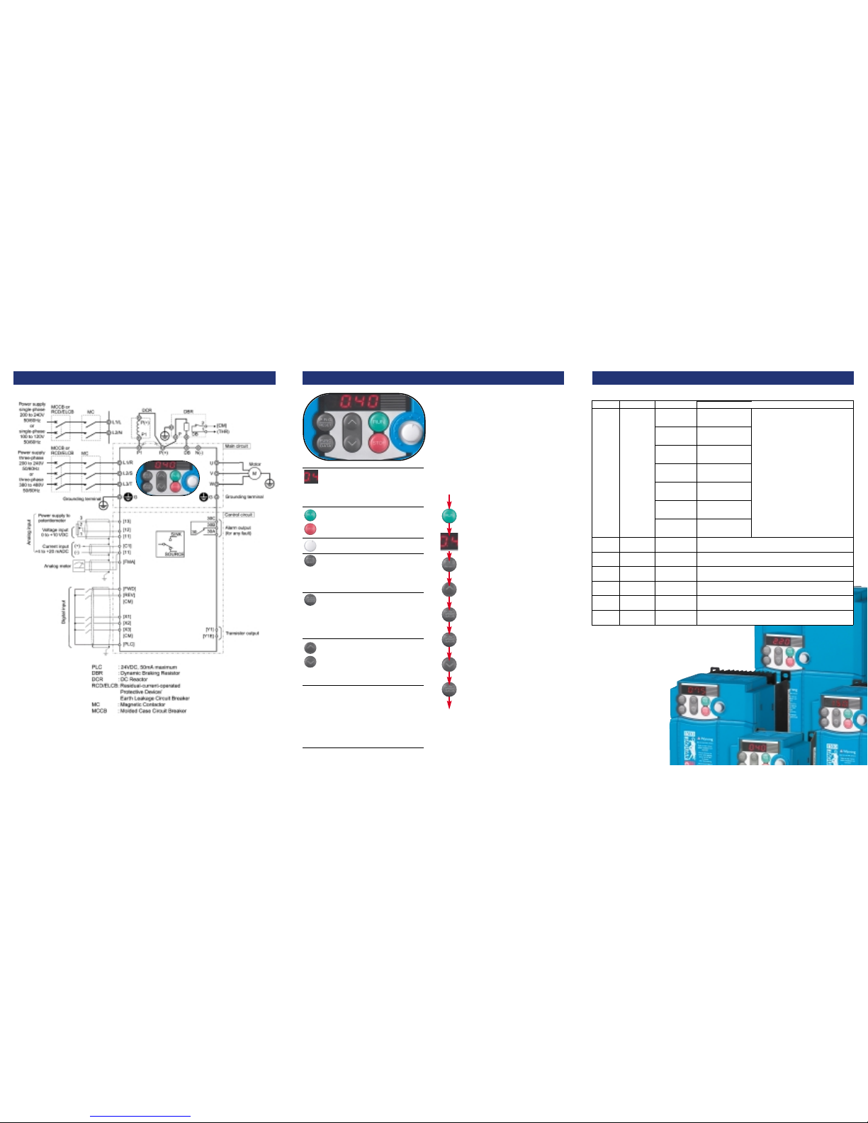
Connections
Menu
Data setting
Data
check
Drive
monitor
I/O check
Maintenance
check
Alarm
information
Data
copy
Displays
1.F##
1.E##
1.C##
1.P##
1.H##
1.J##
1.y##
2.rEP
3.oPE
4.i_0
5.CHE
6.AL
7.CPy
Menu #
#1
#2
#3
#4
#5
#6
#7
F codes
(Fundamental
functions)
E codes
(Extension terminal
functions)
C codes
(Frequency control
functions)
P codes
(Motor parameters)
H codes
(High performance
functions)
J codes
(Application functions)
Y codes
(Application functions)
Main functions
Selecting these codes enables data to
be displayed or changed
Display only those function codes that have been changed from
factory set defaults.
Display Hz, rmp, A, kW, V(O/P), PID values etc.
Display drive control input and output status.
Display maintenance information including accumulated hours
run time.
Display the last four alarm codes and running data at the time of
last trip condition.
Feature for reading, writing and verifying data for transferring to
other drives of same type (remote keypad only).
Programming ModeBasic key operations
7-segment LED display shows In Run mode:
Hertz, Amps, Volts, kW, I/O signal status, run
time, rpm, PID values. In Program mode:
Menus, Function codes and their data. In Alarm mode:
Trip codes and alarm information.
Motor RUN and STOP
keys active only when inverter is operating in
keypad mode.
On-board frequency setting potentiometer.
PRG/RESET key. Use to change operating
modes. In Run mode: press to enter program
mode. In Program mode: press to enter run mode. In
Alarm mode: Resets a trip condition (after fault has
been removed).
FUNC/DATA key. In Run mode: press to change
display from Output frequency _ Motor current
(A)_Power (P) _ Output voltage (V) _ Out. In Program
mode: press to display function code value or to store /
write data to memory. In Alarm mode: Displays
information about alarm state shown on LED panel.
UP/DOWN keys used to scroll through menus
and function codes, also used to increase/
decrease actual set value of function codes
(value must be stored in memory by pressing
FUNC/DATA key). When operating in keypad mode they
are used to increase/decrease motor speed.
Simultaneous Keying In Run mode: STOP + UP
keys together – gives entry to or exit from jogging
operation. In Program mode: STOP + DOWN keys
together – allows changes to special function codes
F00 (Data protection) and H03 (Reset all function codes
to factory set default values). In Alarm mode: STOP +
PRG/RESET keys together – switches to program mode
without resetting trip condition.
Display flashes a frequency value
from on-board pot, say 0.00 (Hz) or
other value.
Press DOWN key until display shows
00.55 (last 5is flashing).
Press FUNC/DATA key until display
shows SAVE (last 5is flashing).
Press PRG/RESET key. Display
shows 1.F__ (1is flashing).
Press FUNC/DATA key. Display
shows 0.75 (5is flashing).
Press UP key three times. Display
shows 1.P__ (1 is flashing).
Press FUNC/DATA key. Display
shows P 02 (2is flashing).
Connect mains, motor and earth
cables as shown in the diagram.
Connect all necessary control
circuits. Check all wiring for
faults / errors. Switch power ON.
If in doubt - consult IMO or CUB instruction manual
Getting started
Example of changing a typical parameter;
Function P02 (motor capacity) from say 0.75kW
to 0.55kW. This would be necessary if a Cub
5A-1 (0.75kW / 230V – 1ph inverter) or Cub
2A5-4 (0.75kW / 415V – 3ph inverter) was to
be used to drive a 0.55kW motor. In this case it
would be necessary to check / change P03
(rated current) and other function codes.
If in doubt - consult IMO or CUB instruction manual
If in doubt - consult IMO or CUB instruction manual
DONE! Display automatically moves to next
function number (P03 in this case)
Press PRG/RESET key to escape.
START
The above data is for basic reference only.
It is strongly recommended to use the correct EMC filter and screened/armoured motor cable (not shown).
WARNING: THIS EQUIPMENT MUST BE EARTHED