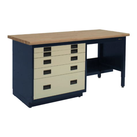
IAC INDUSTRIES LT Series User manual

INDUSTRIES
LTXX FRAME ASSEMBLY
IAC INDUSTRIES
3831 S BULLARD AVE., GOODYEAR, AZ 85338
Phone (714) 990-8997 Fax (714) 990-0557
www.iacindustries.com
REV. (042318P65)Assembly Instructions

2
Table of Contents
Page #
2 Attention Notes
3 Pre-assembly Check List
4 LTXX FRAME ASSEMBLY
5 LT WORKSURFACE INSTRUCTIONS
ATTENTION NOTES:
IAC Industries takes great care in the packaging of its products; however damage
can occur during shipment. Check all packages and parts for any signs of damage. If
damage is evident STOP and contact the carrier that delivered your order. Request a
freight claim inspector to document the damage and begin the freight claim process.
Tools required to assemble your LTXX FRAME products are:
7/16” and 1/2” wrench or socket with ratchet.
Phillips screwdriver 8” long.
Utility knife.
Safety glasses and light duty protective gloves.
NOTE: Power tools are NOT recommended unless they are equipped with a torque
limiting device which can limit the torque to 10 foot lbs maximum at aluminum
attachment points, and 15 foot lbs maximum for all other attachment points.
Unpack your order and separate like parts into separate areas. Be careful not to
damage parts as they are being moved around and put into position. Also be sure all
parts are removed from the packing materials before these materials are thrown
away.
Locate the hardware kits and keep them in a central area. If the assembly is going to
take more than one day, all individual hardware pieces should be returned to a
central location.
Check all parts and hardware kits against the itemized packing list found with the
assembly instructions. If you believe there are parts missing from your order please
contact IAC Industries customer service HOTLINE at 800-989-1422.
WARNING:
ALL PARTICLE BOARD USED IN IAC INDUSTRIES PRODUCTS ARE SOURCED ONLY FROM VENDORS THAT
ARE CARB ATCM PHASE 2 AND TSCA TITLE VI COMPLIANT WITH VALID CERTIFICATES.Drilling, Sawing, Sanding
or Machining Wood products can expose you to wood dust, a substance known to the state of California to cause cancer. Avoid inhaling
dust generated from wood products or use a dust mask to other safeguards for personal protection. This product can expose you to
chemicals, including formaldehyde, which is known to the state of California to cause cancer, and methanol, which is known to the state
of California to cause birth defects or other reproductive harm. For more information please visit, www.P65WARNINGS.CA.GOV/WOOD.
COPY OF VENDOR CERTIFICATE AVAILABLE UPON REQUEST.

3
PRE ASSEMBLY CHECK LIST
Your bench has been carefully packed at the factory to prevent damage during shipment. Unpack all parts
and examine them for damage. Contact your freight carrier for freight claims information if your order was
shipped "freight collect" or "pre-pay and add". Contact IAC Industries at 800 989-1422 if parts are missing.
HARDWARE KIT HWR7006:
HARDWARE KIT COMPONENTS:
900044 BOLT, 5/16-18 X .750 HHW BLACK (8)
900068 WASHER, 1/4 FLAT BLACK (24)
920028 FLOOR GLIDE 5/16-18 X 1.75 X 1.625 DIA (4)
900032 BOLT, 1/4-20 X .750 HHW BLACK (16)
900412 PLATE, STOCK BENCH CONNECTOR –PLATED (4)
990140 ADHESIVE, SILICONE CLEAR 2.8 OZ GE2843TG (NOT SHOWN) (1)
HARDWARE FOR FIXED HEIGHT PEDESTALS (HWR7005)
PLEASE NOTE: This Hardware kit includes the above hardware in HWR7006
as well as the tube inserts that will be needed with the floor glides for a fix height bench.
HARDWARE KIT COMPONENT added to HWR7005:
900096 INSERT, TUBING 2.00X2.00 5/16-18 16GA (4)

4
TOOLS NEEDED: Power or hand held Phillips head screwdriver with #2 tip, 7/16" and 1/2" combination
wrench or thin wall sockets.
LAB TABLE FRAME ASSEMBLY FOR LAMINATE OR HARDWOOD WORKSURFACES
Step 1:
Attach beam connector plates to the ends of the bench support beams using the 5/16-18 x .75 hex head bolts
and 1/4 flat washers supplied as shown. DO NOT TIGHTEN THE HARDWARE.
Step 2:
Place worksurface topside down on smooth flat surface being sure to protect it from damage by foreign
objects. IAC recommends the use of packing type blankets or clean cardboard. Place the support beams on
the worksurface with the open side toward the center of the worksurface and align the slots of the support
beams over the threaded inserts in the worksurface as shown. Use the 1/4-20 x .75 hex head bolts and 1/4
flat washers and thread them into the threaded inserts to attach the beams to the worksurface.
NOTE: DO NOT TIGHTEN THE HARDWARE.

5
Step 3:
Align the workbench pedestals over the ends of the support beams and lower them down over the beam
connector plates so that the plates are on the inside of the pedestal tubing. Align the slots in the pedestal
support beam over the inserts in the worksurface and thread the 1/4-20 x .75 hex head bolts with the 1/4 flat
washers into the inserts. Tighten the beam connector hardware. The frame should now be aligned on the
worksurface to even the overhangs on the right and left sides tighten the beam attachment and the pedestal
support hardware.
NOTE: Do not over tighten the hardware that goes into the threaded inserts in the worksurface as this could
cause the inserts to pull out of the worksurface.
Step 4:
Slide the lab table frame leg extender into the pedestal leg tube making sure the black plastic insert at the end
of the leg extender is exposed. Align the threads of the leg extender with the holes in the pedestal leg tube
and select the desired height of the bench frame.
NOTE: Remember to count the thickness of your worksurface when making this adjustment.
Thread two sets per leg of 1/4-20 x .75 hex head bolts with the 1/4 flat washers into the holes in the pedestal
leg tube and the threaded leg extender and tighten. Thread the floor glide into the black plastic insert of the
leg extender. The floor glides are used to level the bench when assembly is complete and it is put into
position.
Your lab table frame should be complete and can be turned right side up. Make sure two or more persons are
used to turn frame and worksurface right side up. Move table frame and top to its location and make any
adjustments to the floor glides to make sure the lab table frame is level.
PLEASE NOTE: Always lift bench from the metal frame and never from the worksurface.

6
LAB TABLE FRAME ASSEMBLY FOR EPOXY OR TRESPA WORKSURFACES
Step 1:
Attach beam connector plates to the ends of the bench support beams using the 5/16-18 x .75 hex head bolts
and 1/4 flat washers supplied as shown. NOTE: DO NOT TIGHTEN THE HARDWARE.
Place the support beams with the attached connector plates, open side toward the center, on a smooth flat
surface being sure to protect them from damage by foreign objects. IAC recommends the use of packing type
blankets or clean cardboard.
Step 2:
Align the workbench pedestals over the ends of the support beams and lower them down over the beam
connector plates so that the plates are on the inside of the pedestal tubing. Tighten the beam connector
hardware on both sides.
Note: The frame should be aligned on the flat surface to make sure all four corners have the pedestal and
beams flush against the flat surface

7
Step 3: LEG EXTENDER/FIXED HEIGHT PEDESTALS
Slide the lab table frame leg extender into the pedestal leg tube making sure the black plastic insert at the end
of the leg extender is exposed. Align the threads of the leg extender with the holes in the pedestal leg tube
and select the desired height of the bench frame. Thread two sets per leg of 1/4-20 x .75 hex head bolts with
the 1/4 flat washers into the holes in the pedestal leg tube and the threaded leg extender and tighten. Thread
the floor glide into the black plastic insert of the leg extender. The floor glides are used to level the bench
when assembly is complete and it is put into position. Fixed Height pedestals –place the insert that is
provided over bottom of pedestal leg. Using a rubber mallet, or something of force that won’t damage your
items, tap the insert into place. Once the insert has been secured, the floor glide can now be installed.
TABLE TOP INSTALLATION
Step 4:
The frame is now ready to have the table top installed. With some help turn the frame right side up.Before
installing the table top it is very important to make sure suspended cabinets and any other items that are
under the table top are installed and secured. When the table worksurface is installed it is difficult to make
changes.
Check the table top before gluing it down to make sure of its location on the frame is correct. Also make sure
they are not obstructed on the beams or pedestals. When all the double checking is done start by cleaning
the frame and the underside of the worksurface to make sure the two will make a clean seal. Apply several
“Quarter” size drops of silicone along the top of the support beams and the top of the pedestal crossbeams at
about 6” spacing as shown below.
It is not necessary to apply a lot of silicone, when the table top is installed the silicone will spread out.

8
36"
24"
30"
CAUTION: Epoxy and Trespa table tops are heavy and can be very heavy depending on the overall size. Be
sure there are enough people lifting the table tops during the installation process to avoid injury.
IAC Lab frames a table tops are designed to have the following overhangs:
For 24” deep table tops going on a 24” deep frame the side overhang is 2”, the rear overhang is 1”.
For 30” deep table tops going on a 30” deep frame the side overhang is 2”, the rear overhang is 2 ½”.
For 36” deep table tops going on a 36” deep frame the side overhang is 2”, the rear overhang is 4 ½”.
It is a good idea to tape, or somehow mark the underside of the table top with these dimensions in order to
make is easier to install the table tops properly.
These dimensions can be very important depending on the type options ordered or to be retro-fitted to the
table frames at a later date.
Table of contents
Other IAC INDUSTRIES Indoor Furnishing manuals
Popular Indoor Furnishing manuals by other brands

Walker Edison
Walker Edison BTOTMM Assembly instructions

modway
modway EEI-3801 manual

Twin-Star International
Twin-Star International Bell'O BFA50-94898-DE1 Assembly

KEUCO
KEUCO Royal Lumos 14307 1723 3 Series Instructions for use

Lipper
Lipper 574 Assembly guide

Home affaire
Home affaire BELFORT Assembly Instructions Instruction Manual