manuals.online logo
Brands
  1. Home
  2. •
  3. Brands
  4. •
  5. IAI
  6. •
  7. Power Supply
  8. •
  9. IAI RCON-SC User manual

IAI RCON-SC User manual

Model Plate (Large)
Refer to “External Dimensions”
for the attached position.
Model Plate (Large)
Refer to “External Dimensions”
for the attached position.
Serial Numbe
r
-SC, -PS2
200V Power Supply Unit, 200V Driver Unit,
Fan Unit, Terminal Unit for 200V
First Step Guide First Edition
Thank you for purchasing our product.
Make sure to read the Safety Guide and detailed Instruction Manual (DVD) included with the
product in addition to this First Step Guide to ensure correct use.
This Instruction Manual is original.
 Using or copying all or part of this Instruction Manual without permission is prohibited.
 The company names, names of products and trademarks of each company shown in the sentences
are registered trademarks.
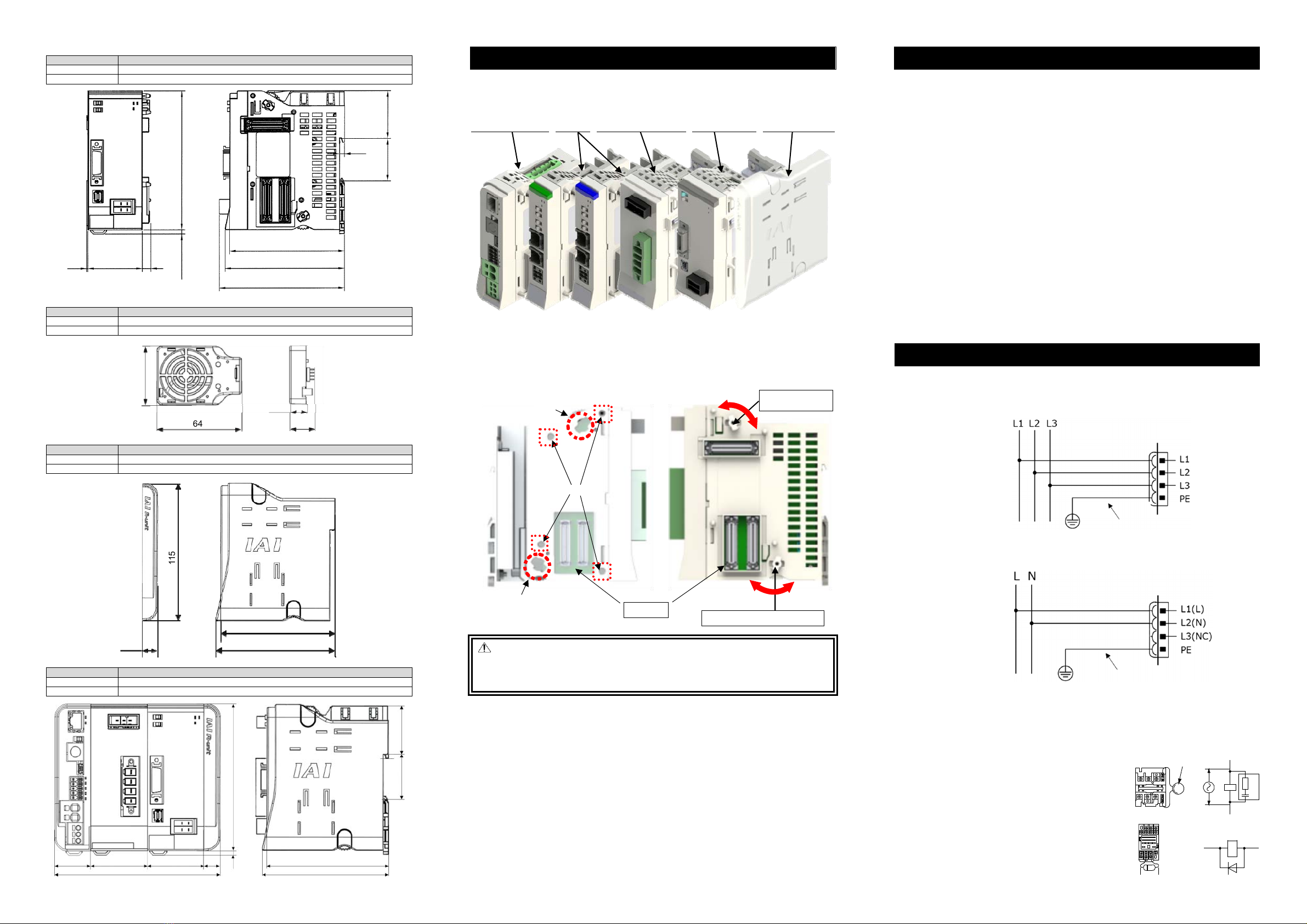
R-unit constructs a systemwide combining the Gateway Unit (RCON/RSEL), 24V and 200V Driver Units,
Extension Unit, Simple Absolute Unit, Fan Unit and Terminal Unit.
In this guide, describes about the 200V Power Supply Unit, 200V Driver Unit, Fan Unit and Terminal Unit for
200V.
For instruction of other units, refer to the first step guide and instruction manual (DVD) of each unit.
This product is comprised of the following parts if it is of standard configuration.
If you find any fault in the contained model or any missing parts, contact us or our distributor.
1. Parts
(1) 200V Power Supply Unit
No. Part Name Model
Numbe
r
Remarks
1 200V Power Supply
Unit
Refer to “How to read the model
plate”, “How to
r
ead the model code” 1
Accessories
2 Terminal Unit for 200V RCON-GW-TRS 1 Not enclosed in TRN Type
3 Fan Unit RCON-FU 1
4 Power Connector SPC5/4-STF-7.62
(Manufactured by PHOENIX CONTACT)
1
5 First Step Guide ME0397 1 This Manual
6 Safety Guide M0194 1
(2) 200V Driver Unit
No. Part Name Model
Numbe
r
Remarks
1 200V Driver Unit Refer to “How to read the model
plate”, “How to read the model code” 1
Accessories
2
Fan Unit for 200V Drive
r
RCON-FUH 1
3 Dummy Plug DP-6 1
4 First Step Guide ME0397 1 This Manual
5 Safety Guide M0194 1
2. Teaching Tool (Please purchase separately)
A teaching tool such as PC software is necessary when performing the setup for position setting, parameter
setting, etc. that can only be done on the teaching tool. Please prepare either of the following teaching tools.
No. Part Name Model
1 PC Software
SEL Controlle
r
:I
A
-101X/N
Position Controller: IA-OS
RCM-101-MW/USB
2
Touch Panel Teaching Pendant TB-02 (Standard
/
Dead Man’s Switch Mounted)
TB-02/TB-02D
3 Touch Panel Teaching Pendant TB-03 TB-03
3. Instruction manuals related to this product, which are contained in the instruction manual (DVD).
No. Name Manual No.
1 RCON System Instruction Manual ME0384
2 RSEL System Instruction Manual ME0392
3 PC Software RCM-101-MW/RCM-101-USB Instruction Manual ME0155
4 PC Software I
A
-101-MW/USB Instruction Manual ME0154
5
Touch Panel Teaching Pendant TB-02 Applicable for Position Controller Instruction Manual
ME0355
6
Touch Panel Teaching Pendant TB-02 Applicable for Program Controller Instruction Manual
ME0356
7
Touch Panel Teaching Pendant TB-03 Wired Link Applicable for Position Controlle
r
Instruction Manual
ME0376
8
Touch Panel Teaching Pendant TB-03 Wired Link Applicable for Program Controlle
r
Instruction Manual
ME0377
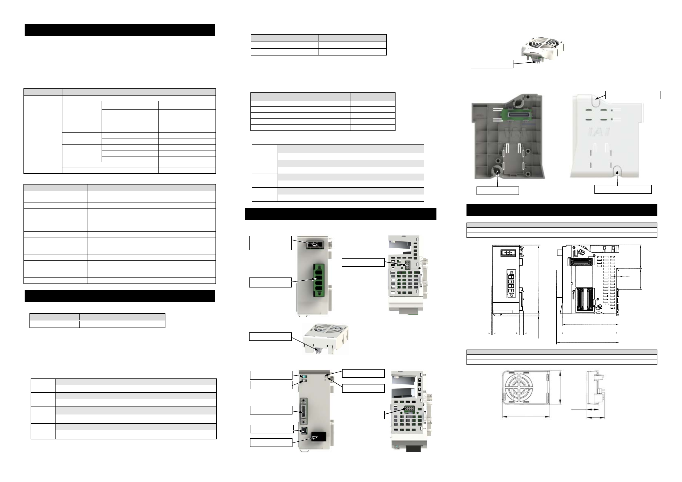
4. How to read the model plate (This design is what is after UL/CE acquired.)
(1) 200V Power Supply Unit
(2) 200V Driver Unit
(3) Fan Unit
Mark Explanation of Mark
Use IAI specified cables only.
Where residual-current-operated protective device (RCD) is used for
protection in case of direct or indirect contact, only RCD of Type B is
allowed on the supply side of this Electrotonic Equipment (EE).
Do not touch terminals within 10 minutes after disconnect the power.
Risk of electric shock.
Do not touch product when power is ON. Risk of burn.
5. How to read the model code
(1) 200V Power Supply Unit
(2) 200V Driver Unit
Type : SC
60-700W Motor
1 axis
60
100
100
150
200
200
300
400
600
750
60W Servo-motor
100W Servo-motor
100W Servo-motor (for LSA)
150W Servo-motor
200W Servo-motor
200W Servo-motor (for LSA, DD)
300W Servo-motor (for LSA)
400W Servo-motor
600W Servo-motor
750W Servo-motor
(3) Fan Unit
1. Specifications of Power Supply
Item Specification
Power Input Voltage Range 200 to 230V AC ±10%
Power Supply Frequency Range 50/60Hz
Cu
r
r
ent Amperage Refer to “Current Amperage”
In-Rush Curren
t
25A/axis (with in-rush current limit circuit)
Instantaneous Power Outage Endurance 20ms (with power supply frequency at 50Hz)
16.3ms
(
with power suppl
y
frequenc
y
a
t
60Hz
)
Protection Function a
g
ainst Electric Shoc
k
Class Ⅰ
Leak Curren
t
3.0mA or less
2. Specifications of Control Part
Item Specification
Number of Controlled Axes RCON System 1 to 16 axes, RSEL System 1 to 8 axes
Corresponding Motor Capacity 60W to 750W
Corresponding Encoder Incremental Serial, Battery-less Absolute, ABZ (UVW) Parallel, Spurious Absolute
and Index Absolute
Field Network Interface CC-Link, CC-Link IE Field, DeviceNet, EtherCAT, EtherNet/I
P
, PROFIBUS-D
P
,
PROFINET IO
Pulse Train Type Unavailable to Control
Brake Output Voltage 45V DC ±10% (Overexcitation 90V)
Connectable Brake Power Max 7W
Calendar Feature Maintained Duration: Approx. 10 days, Charge Time: Approx. 100 hours
Applied Safety Category B (Safety category applicable type is capable to achieve 4 with external circuit)
Driver Source Cutoff System Drive source cutoff with semiconductor (Power MOSFET)
Stop Input Break Contact Input
Stop Action Turning servo OFF + Drive source cutoff
Enable Input None
T. P. Enable Input Available
Enable Action Turning servo OFF
Protective functions Overcurrent, temperature error, encoder line breakage and overload
Preventive / Predictive Maintenance Feature
Electrolytic capacitor capacity dropdown and Fan revolution dropdown
Driver Unit LED Display Refer to “Troubleshooting (LED Display)”
Brake Compulsory Release Feature Brake release switch equipped on 200V Driver Unit
Jog Jog switch equipped on 200V Driver Unit
Cable Length Motor Cable: 20m or less, Encoder Cable: 20m or less
Oversea Certifications Planned to acquire CE and UL
3. Environmental Specifications
Item Specification
Environment
Environment of Use Pollution Degree 2
Surrounding Air Temperature 0 to 55C
Surrounding Humidity 85% RH or less (non-condensing)
Peripheral Ambience of Use Refer to “Installation Environment”
Surrounding Storage Temperature -20 to 70C
Vibration Durability
Frequency 10 to 57Hz/Swing width: 0.075mm
Frequency 57 to 150Hz/Acceleration: 9.8m/s2
XYZ Each direction Sweep time: 10min. Number of sweep: 10times
Protection Class IP20
Altitude 1000m
Cooling Method Forced air cooling with fan unit
Dielectric Withstanding Voltage 1500V for 1 min between power supply terminal and PE
Overvoltage category Ⅰ
Product Check
Basic Specifications
Warnin
g
: Operation of this equipment requires detailed installation and operation instructions
which are provided on the DVD Manual included in the box this device was
packaged in. It should be retained with this device at all times.
A copy of the DVD Manual can be requested by contacting your nearest IAI Sales
Office listed at the back cover of the Instruction Manual or on the
F
irst Step Guide.
1B
Fan Unit
200V Power
Supply Unit
Fan Unit for 200V Drive
r
200V Driver Unit
Terminal Unit for
200V
Model
Se
r
ial Numbe
r
Model
Model Plate (small)
It is attached on the
bottom of the panel
front face.
Model
Serial Numbe
r
Model Plate (small)
It is attached on the
bottom of the panel
front face.
Serial
Model
(Partially)
Serial Numbe
r
Model
RCON - SC - 1
<Number of Axes>
1 : 1 axis
< Series >
<Type>
SC : 200V AC Servo-motor
<Type>
FU : Fan Unit
FUH : Fan Unit for 200V
RCON - FUH
< Series >
RCON - PS2 - 3 -TRN
< Series >
<Power-supply Voltage >
3 : Sin
g
le-phase/Three-phase 200V
<Type>
PS2 : 200V
Power Suppl
y
Uni
t
<Option>
TRN : With No Terminal Uni
t
Current Amperage
The current amperage should be divided into the control power capacity and motor power capacity.
In this guide, describes about the current amperage of the control power supply and 200V motor power
supply. For the current amperage of the 24V motor power supply, refer to the first step guide (ME0383) and
instruction manual (DVD) of RCON 24V Driver Unit.
The control power supply should be input from the control power supply connector on the gateway unit. The
motor power supply should be input from the 200V input connector on the 200V power supply unit.
The specifications related to the power capacities should be as shown below.
[Control Power Supply]
Item Specification
Power Supply Voltage 24V DC ±10%
Control Power Capacity
(for one unit)
Gateway unit
(terminal unit included)
RCON Gateway Unit 0.8A (Ethernet option: Not equipped)
1.0A (Ethernet option: Equipped)
SEL Unit 1.2A
24V Driver unit
Brake: Not equipped 0.2A
Brake: Equipped (one-axis type) 0.4A
Brake: Equipped (two-axis type) 0.6A
200V Driver uni
t
(200V power supply
unit included)
Brake: Not equipped 0.2A
Brake: Equipped 0.5A
Extension unit
SCON Extension Unit 0.1A
PIO/SIO/SCON Extension Unit 0.3A
PIO Unit 0.2A
Simple absolute unit (in common for all types) 0.2A
EC Connection Unit 0.1A
[200V Motor Power Supply]
Actuator Motor Wattage Motor Power Capacity Peek Max. Motor Power Capacity
60 138 414
60 (RCS3-CTZ5) 197 591
100 234 702
100S (LSA) 283 851
150 328 984
200 421 1263
200S (DD) 503 1509
200S (Excluding LSA (S)-N15H) 486 1458
200S (LSA (S)-N15H) 773 2319
300S(LSA) 662 1986
400 920 2760
400 (RCS3-CT8) 1230 3690
600 1164 2328
600 (DD) 1462 4386
750 1521 3042
750S 1521 4563
Restrictions in Unit Connection
(1) Current Restrictions
Shown below is the restricting values of current for selecting calculation.
Item Restricting Value of Current for Selecting Calculation
Control Power Supply (CP) 9.0A or less
The capacity necessary in the control power supply should be figured out by [Total of control power
capacity of used units].
In the table of the capacity [Control Power Supply] shown above, add the power capacity of all the units
constructing the system and check that it does not exceed the restricting values of current for selecting
calculation described in Restrictions in Unit Connection.
Also, the gateway units should not be included for the calculation.
Shown below is some examples for calculation.
[Control Power Supply] * The gateway units should not be included for the calculation.
Example 1 200V Actuator × 8 axes, All axes equipped with brake
200V Driver unit (with brake) 0.5A × 8 = 4.0A ⇒ OK
Example 2 200V Actuator × 16 axes, All axes equipped with brake
200V Driver unit (with brake) 0.5A × 16 = 8.0A ⇒ OK
Example 3
24V Actuator × 8 axes, All axes equipped with brake (2 axes/unit), All axes simple absolute type
200V Actuator × 8 axes, All axes equipped with brake
24V Driver unit (with brake) 0.6A × 4 + Simple absolute 0.2A × 8
+200V Driver unit (with brake) 0.5A × 8 = 8.0A ⇒ OK
Example 4
200V Actuator × 16 axes, All axes equipped with brake + PIO/SIO/SCON Extension Unit one unit, PIO Unit 7 units
200V Driver unit (with brake) 0.5A × 16 +
PIO/SIO/SCON Extension Unit 0.3A × 1 + PIO Unit 0.2A × 7 = 9.7A ⇒ NG
(2) 200V Motor Power Supply Current Restrictions
Shown below is the restricting values for selecting calculation.
Item
Restricting Value for Selecting Calculation
200V Motor Power Supply (Single-phase)
1600W
200V Motor Power Supply (Three-phase)
2400W
The capacity necessary in the motor power supply should be figured out by [Total of control power
capacity of used units].
In the table of the capacity [Motor Power Supply] shown above, add the power capacity of all the actuator
motor wattages constructing the system and check that it does not exceed the restricting values of
current for selecting calculation described in Restrictions in Unit Connection.
However, apply the motor wattage for calculation for the actuators listed below.
Actuator Model Code Motor Wattage for
Calculation
RCS3-CTZ5 120W
LSA-S6S□/S8S□/S8H□/N10S□ 300W / 1 Slider
LSA-S10SM/H8SM/H8HM/L15SM/N15SM/N15HM/N19SM 400W / 1 Slider
LSA-S10SS/S10HS/H8SS/H8HS/L15SS/N15SS/N15HS/N19SS
600W
LSA-W21S□、RCS3-CT8 800W / 1 Slider
Shown below is some examples for calculation.
[200V Motor Power Supply]
Example 5
One axis for each of actuator of 200W motor, actuator of 300W motor and actuator of 600W
moto
r
200W × 1 axis + 300W ×1 axis + 600W × 1 axis = 1100W
⇒
Single-phase OK, Three-phase OK
Example 6 RCS-CTZ5 × 1 axis, actuator of 200W motor × 7 axes
120W + 200W × 7 axes = 1520W⇒ Single-phase OK, Three-phase OK
Example 7 actuator of 200W motor × 6 axes, LSA-S10SM (Multiple Slider) × 1 axis
200W × 6 axes + 400W × 2 = 2000W ⇒ Single-phase NG, Three-phase OK
Example 8 actuator of 200W motor × 16 axes
200W × 16 axes = 3200W ⇒ Single-phase NG, Three-phase NG
(1) 200V Power Supply Unit
Front Top
(2) Fan Unit
(3) 200V Driver Unit
Front Top
(4) Fan Unit for 200V Driver
(5) Terminal Unit for 200V
Left Side Right Side
1. 200V Power Supply Unit
Item Specification
External Dimensions 45.2W × 115H × 95D [mm]
Mass Approx. 393g (fan unit weight excluded)
2. Fan Unit
Item Specification
External Dimensions 34.2W × 49H × 12.5D [mm]
Mass Approx. 16g
Names for Each Part External Dimensions
External
Regenerative
Connector
200V AC
Input Connector
FAN Connector
FAN Connector
FAN Connector
Jog Switch
Brake Switch
Encoder Connector
Driver Stop Connector
SYS LED
T RUN LED
Motor Connector
Fan Connector
Bottom Parts for Terminal Unit
Upper Parts for Terminal Unit
34.2
49
12.5
18.4
115 3.5
7
45.2
39.6
4
35.2
95
198.8
104.5
Linked Connector
Surge absorber
R
C
+24V 0V
+24V 0V
+-
45.2 1
39.6
4
115
35.2
95
3.5
98.8
7
103.5
3. 200V Driver Unit
Item Specification
External Dimensions 45.2W × 115H × 95D [mm]
Mass Approx. 438g (fan unit weight excluded)
4. Fan Unit for 200V Driver Unit
Item Specification
External Dimensions 44.5W × 64H × 12.5D [mm]
Mass Approx. 20g
5. Terminal Unit for 200V
Item Specification
External Dimensions 12.6W × 115H × 95D [mm]
Mass Approx. 40g
6. Linking Units
Item Specification
External Dimensions (30 + 45.2 + 45.2 + 12.6) W × 115H × 95D [mm]
Mass Approx. 1,077g
RCON/RSEL Systems possesses a locking structure with unit linking system. The 200V Power Supply Unit
is to be linked on the right of the 24V Driver Unit in the front view. The 200V Driver Units are to be linked on
the right of them for the necessary number of units, and the Terminal Unit for 200V come on the further right.
For the terminal unit, make sure to use the Terminal Unit for 200V enclosed to the 200V Power Supply Unit.
Gateway Unit (Left End) - Driver Unit - Power Supply Unit for 200V - Driver Unit for 200V - Terminal Unit for 200V
Unit should be linked in the process shown below. (Make sure it gets linked before connected to the DIN rails.)
1) Twist the operation parts of the link upper parts and the link bottom parts towards the panel side and
place them at the panel side end.
2) Adjust the position of two units so the link upper parts come to Point [A], link bottom parts to [B] and the
four positioning bosses to [C] and all the six points fit to each other.
3) Once positioning is done, firmly insert the connectors at two points.
4) Twist the operation parts of the link upper parts and the link bottom parts towards the rear side till they
make click feeling.
Danger: When there is a unit of 200V, make sure that the terminal unit on the right is the Terminal
Unit for 200V (RCON-GW-TRS) enclosed to the 200V Power Supply Unit. The Terminal
Unit for 24V has a structure that does not allow itself connected to the 200V units,
however, it could be forcefully inserted, which could cause fire on the connector as well as
damage on it.
Installation Environment
This product is capable for use in the environment of pollution degree 2 *1 or equivalent.
*1 Pollution Degree 2: Environment that may cause non-conductive pollution or transient conductive
pollution by frost (IEC60664-1)
1. Installation Environment
Do not use this product in the following environment.
 Location where the ambient temperature is out of the range between 0 and 40C
 Location where condensation occurs due to abrupt temperature changes
 Location where relative humidity exceeds 85%RH
 Location exposed to corrosive gases or combustible gases
 Location exposed to significant amount of dust, salt or iron powder
 Location subject to direct vibration or impact
 Location exposed to direct sunlight
 Location where the product may come in contact with water, oil or chemical droplets
 Environment that blocks the air vent Refer to [Installation and Noise Elimination]
When using the product in any of the locations specified below, provide a sufficient shield.
 Location subject to electrostatic noise
 Location where high electrical or magnetic field is present
 Location with the mains or power lines passing nearby
2. Storage and Preservation Environment
The storage and preservation environment should comply with the same standards as those for the
installation environment. However, the ambient temperature should be from -20 to 70°C and relative
humidity at 85%RH or below. In particular, when the machine is to be stored for a long time, pay close
attention to environmental conditions so that no condensation forms.
Unless specially specified, moisture absorbency protection is not included in the package when the machine
is delivered. In the case that the machine is to be stored and preserved in an environment where
condensation is anticipated, take the condensation preventive measures from outside of the entire package,
or directly after opening the package.
Installation and Noise Elimination
1. Protective Ground
For the grounding, the grounding resistance should be set to 100Ω or less (Class D grounding).
The wiring should apply a twist line or an annealed copper wire of 2.0mm2 (AWG14) or more with an
isolation sheath with its rated temperature at 60°C or higher.
[200V Three-phase Type]
[200V Single-phase Type]
2. Noise Elimination Grounding (Frame Ground)
Noise elimination grounding (frame ground) is conducted on the gateway unit side.
3. Precautions regarding wiring method
Separate I/O lines, communication lines and encoders, power source and supply lines from each other to
reduce the influence to each other.
4. Noise Sources and Elimination
Carry out noise elimination measures for electrical devices
on the same power path and in the same equipment.
The following are examples of measures to eliminate noise
sources.
1) AC solenoid valves, magnet switches and relays
[Measure] Install a Surge absorber parallel with the coil.
2) DC solenoid valves, magnet switches and relays
[Measure] Consider whether to attach a diode in parallel
to the coil or to use a diode built-in type.
Linking Units
Rear Side (Link)
Link Upper Parts
Operation Part
[C]
[A]
Link Bottom Parts Operation Part
[B]
Connector
Panel Side
(Unlink) Rear Side
(Link)
Panel Side
(Unlink)
64
44.5
18.4
12.5
115
12.6
95
98.8
95
98.8
35.2 39.6
4
45.2 45.2
30
133
12.6
115
Motor Power Supply Connector
for 200V Motor Driving
Grounding resistance
at 100Ω or less
(Class D grounding)
St rand or annealed copper wire:
Connect with an eart h line of
2.0mm
2
(AWG14)ormore
Motor Power Supply Connector
for 200V Motor Driving
Grounding resistance
at 100Ω or less
(Class D grounding)
St rand or annealed copper wire:
Connect with an eart h line of
2.0mm
2
(AWG14) or more
Wiring Layout for Motor/Encoder Cables
Note 1 The 200V Servo Motor Actuators below are not capable to be connected to the 200V Driver Units.
(1) Motor types other than those from 60W to 750W
(2) Encoder types other than Battery-less Absolute, Incremental, Spurious Absolute and Index Absolute
(3) For Three-phase 200V, combination that exceeds 2400W in total of Actuator Wattages connected to
200V Driver Units
(4) For Single-phase 200V, combination that exceeds 1600W in total of Actuator Wattages connected to
200V Driver Units
(5) Servo Pressing Type
(6) SCARA Robot
(7) CT4 Series
(8) ZR Series
When it is necessary to connect actuators from (1) to (4) above, use the SCON Extension Unit and
SCON-CB.
Also, DD/DDA and LSA-W21S are not conformed with Single-phase 200V
Note 2 There is a built-in regenerative resistor of 60W equipped in 200V Driver Unit and 200V Power
Supply Unit.
The regenerative resistor is basically not necessary, but use this External Regenerative Resistor
Unit in case of shortage in regenerative resistance.
200V Driver Unit Connection Cable List
No.
Actuator
Series Target type Motor cable Motor robot cable Encoder cable Encoder robot cable
(1) RCS4
RCS4CR CB-RCC1-MA□□□ CB-X2-MA□□□ ― CB-X1-PA□□□
(2) RCS3(P)
RCS3(P)CR
CTZ5C
CT8C CB-RCC1-MA□□□ CB-X2-MA□□□ ― CB-X1-PA□□□
Those other than above CB-RCS2-PA□□□ CB-X3-PA□□□
(3)
RCS2
RCS2CR
RCS2W
RTC□L
RT6 CB-RCC1-MA□□□ CB-X2-MA□□□
CB-RCS2-PLA□□□ CB-X2-PA□□□
Those other than above CB-RCS2-PA□□□ CB-X3-PA□□□
(4) RCS2
with no loadcell
equipped
RA13R
CB-RCC1-MA□□□ CB-X2-MA□□□
CB-X2-PLA□□□ CB-X2-PLA□□□
RA13R
with brake
(with brake box)
[Between Actuator and
Brake Box]
CB-RCS2-PLA□□□
[Brake Box and controller]
CB-RCS2-PLA□□□
[Between Actuator and
Brake Box]
CB-X2-PLA□□□
[Brake Box and controller]
CB-X2-PLA□□□
RA13R
with brake
(with no brake box)
[Between Actuator and
Brake Box]
CB-RCS2-PLA□□□
[Between Actuator and
Brake Box]
CB-X2-PLA□□□
(5)
IS(P)B
IS(P)DB
IS(P)DBCR
― CB-X2-MA□□□ ―
CB-X1-PA□□□
* For cable length 21m or
more and 30m or less in
battery-less absolute type;
CB-X1-PA□□□-AWG24
Option:
with limit switch type
CB-X1-PLA□□□
* For cable length 21m or
more and 30m or less in
battery-less absolute type;
CB-X1-PLA□□□-AWG24
(6)
IS(P)A
IS(P)DA
IS(P)DACR
SSPA
SSPDACR
IF
FS
RS
― CB-X2-MA□□□ ―
CB-X1-PA□□□
Option:
with limit switch type CB-X1-PLA□□□
(7) NSA ― CB-X2-MA□□□ ― CB-X1-PA□□□
(8) NS
― CB-X2-MA□□□ ―
CB-X3-PA□□□
Option:
with limit switch type CB-X2-PLA□□□
(9)
DD(A)
DD(A)CR
DDW
T18□
LT18□ ―
CB-X2-MA□□□
― CB-X3-PA□□□
H18□
LH18□ CB-XMC1-MA□□□
(10) LSA W□□□ ― CB-XMC1-MA□□□ ― CB-X2-PLA□□□
Those other than above CB-X2-MA□□□ CB-X3-PA□□□
(11) LSAS ― CB-X2-MA□□□ ― CB-X1-PA□□□
(12) IS(P)WA ― CB-XEU1-MA□□□ ― CB-X1-PA□□□-WC
Power Supply and Stop Circuit (Example)
In the diagram below shows a circuit related to RCON drive source cutoff. The 200V Motor Power Supply is
a supply to the 200V Power Supply Unit. The circuit related to the drive-source cutoff is on the driver unit
side.
 Each driver unit possesses a drive source cutoff circuit by semiconductor. The motor power should be
cut off by STOP Signal. The drive source cutoff circuit by semiconductor possesses features to detect
the overcurrent and to limit the in-rush current.
Note 1 RCON-GW : If nothing is connected to the SIO connector, S1 and S2 will be short-circuited in the controller.
RCON-GWG : If nothing is connected to the SIO connector, S1 and S2 will not be short-circuited in the controller.
To short-circuit, connect the supplied dummy plug DP-5 to the SIO connector.
Note ●Consider the cable diameter and length that would not drop the voltage for the drive-source cutoff connector wiring.
●There could be a case that the voltage drops on the controller power supply and generate an alarm due to the cable
diameter and length. In such a case, adjust the output voltage on the power supply so the voltage supplied to the
controller is kept at 24V.
Troubleshooting (LED Display)
In this section, describes for LED.
Utilize them to check normal operation status and recovery after error occurrence.
(1) 200V Driver Unit
Panel
Display
Color Status Explanation
T RUN GN
Illuminating Inside bus communication in
normal conditions
Flashing
Waiting for initializing
communication,
Initializing communication erro
r
OR Illuminating Inside bus communication in error
SYS
GN Illuminating Turning servo ON
OFF Turning servo OFF
RD Illuminating Alarm being generated, STOP
signal input ON
Head Office: 577-1 Obane Shimizu-KU Shizuoka City Shizuoka 424-0103, Japan
TEL +81-54-364-5105 FAX +81-54-364-2589
website: www.iai-robot.co.jp/
Ober der Röth 4, D-65824 Schwalbach am Taunus, Germany
TEL 06196-88950 FAX 06196-889524
SHANGHAI JIAHUA BUSINESS CENTER A8-303, 808, Hongqiao Rd. Shanghai 200030, China
TEL 021-6448-4753 FAX 021-6448-3992
website: www.iai-robot.com
Technical Support available in USA, Europe and China
Head Office: 2690 W. 237th Street, Torrance, CA 90505
TEL (310) 891-6015 FAX (310) 891-0815
Chicago Office: 110 East State Parkway, Schaumburg, IL 60173
TEL(847) 908-1400 FAX (847) 908-1399
TEL (678) 354-9470 FAX (678) 354-9471
website: www.intelligentactuator.com
Atlanta Office: 1220 Kennestone Circle, Suite 108, Marietta, GA 30066
825 PhairojKijja Tower 7th Floor, Debaratana RD., Bangna-Nuea, Bangna, Bangkok 10260, Thailand
TEL +66-2-361-4458 FAX +66-2-361-4456
website:www.iai-gmbh.de
website:www.iai-robot.co.th
Manual No.: ME0397-1B
T RUN LED
SYS LED
Power Supply Cable
(Cables to be prepared by
customer)
* Use cable with diameter large
enou
g
h to accept current.
Field Network
Connectable Actuators
(
N
o
t
e
1)
PLC
Regenerative Resistances Unit (Note 2)
RESU-2/RESUD-2
PSA-24
Power Supply
Unit
TB-02
TB-03
IA-101-X
IA-101-N
RCU-101-MW
RCM-101-USB
Single-phase
/Three-phase
AC200V
Gateway Unit 200V Power Supply Unit 200V Driver Unit
SIO Connector
System I/O
Connector
Motor Power Supply
Connector
for P/A/D Drivers
Control
Power
Connector
Note 1
Control
Power
Emergency
Stop Reset
Switch
Emergency
Stop Switch
Stop Switch on
Teaching Pendant
Motor Power Supply
Connector
Motor Power Supply
High-Side Protection Circuit

This manual suits for next models

1

Other IAI Power Supply manuals

IAI PS241 User manual

IAI

IAI PS241 User manual

IAI PSA-24 User manual

IAI

IAI PSA-24 User manual

IAI PSA-24 User manual

IAI

IAI PSA-24 User manual

Popular Power Supply manuals by other brands

Azure Aqua AC4203 user manual

Azure

Azure Aqua AC4203 user manual

HP 4142B Reference manual

HP

HP 4142B Reference manual

Vimar ELVOX 6942 Installer's guide

Vimar

Vimar ELVOX 6942 Installer's guide

Texas Instruments UCC28C56EVM-066 user guide

Texas Instruments

Texas Instruments UCC28C56EVM-066 user guide

Seneca Z109S-1 manual

Seneca

Seneca Z109S-1 manual

Soncoz LP1 user manual

Soncoz

Soncoz LP1 user manual

Enttec PSAT Installation sheet

Enttec

Enttec PSAT Installation sheet

Keysight Technologies N6900 Series Operating and service guide

Keysight Technologies

Keysight Technologies N6900 Series Operating and service guide

daisalux PBS-20 manual

daisalux

daisalux PBS-20 manual

Tektronix KEITHLEY SourceMeter 2400 Series Calibration and Adjustment Manual

Tektronix

Tektronix KEITHLEY SourceMeter 2400 Series Calibration and Adjustment Manual

Enercell 16VDC user guide

Enercell

Enercell 16VDC user guide

VOLTCRAFT SNPS-90 operating instructions

VOLTCRAFT

VOLTCRAFT SNPS-90 operating instructions

Daitron MFS50-12 instruction manual

Daitron

Daitron MFS50-12 instruction manual

Camtec HSE03201 Series quick start guide

Camtec

Camtec HSE03201 Series quick start guide

Cooler Master eXtreme Power 650W user manual

Cooler Master

Cooler Master eXtreme Power 650W user manual

Elk Products ELK-P1224 Installation and setup guide

Elk Products

Elk Products ELK-P1224 Installation and setup guide

Vanderbilt PSU241038 quick start guide

Vanderbilt

Vanderbilt PSU241038 quick start guide

Delta Elektronika M 24-12 HE manual

Delta Elektronika

Delta Elektronika M 24-12 HE manual

manuals.online logo
manuals.online logoBrands
  • About & Mission
  • Contact us
  • Privacy Policy
  • Terms and Conditions

Copyright 2025 Manuals.Online. All Rights Reserved.