PLENTZIA BIDEA, 3 BILLELA AUZOTEGIA
48100 MUNGIA- SPAIN
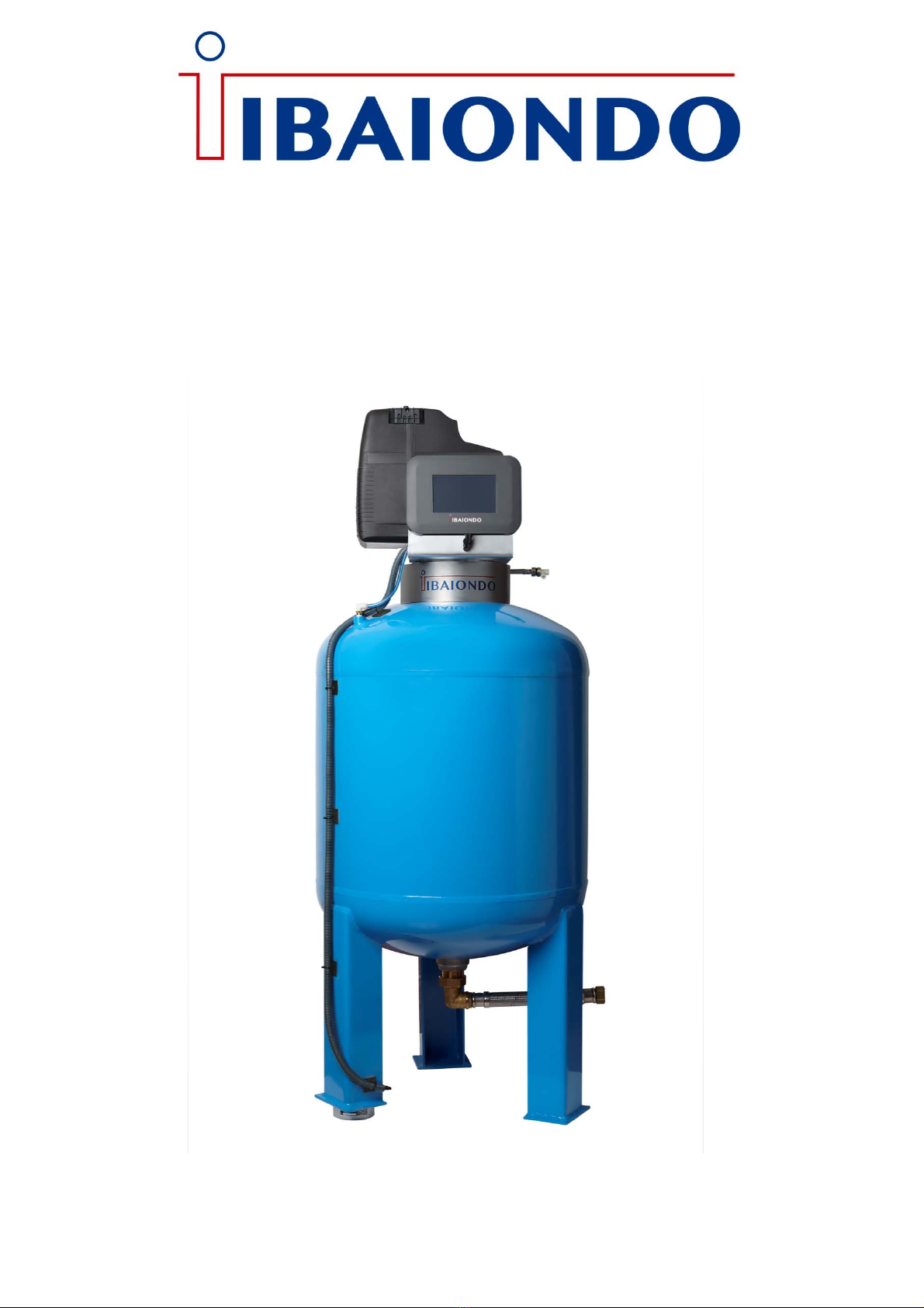
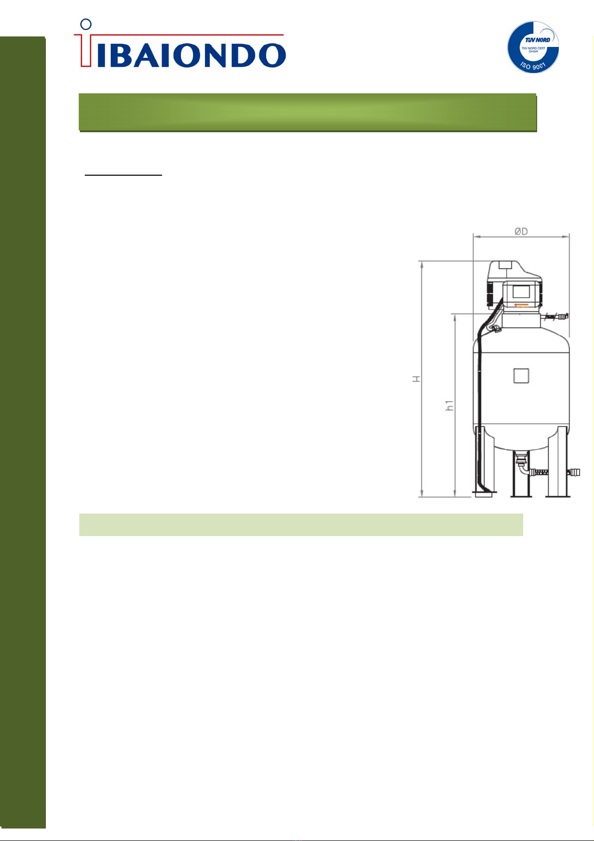
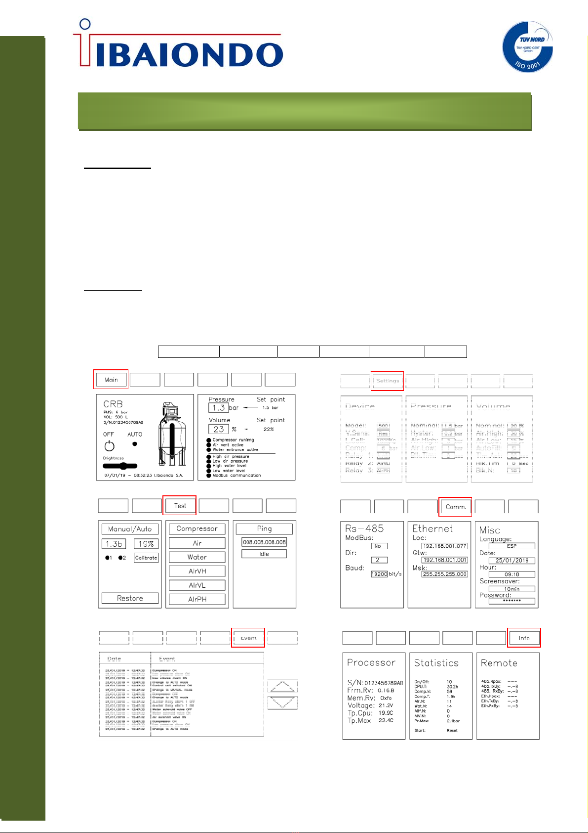
CRB AUTOMAT
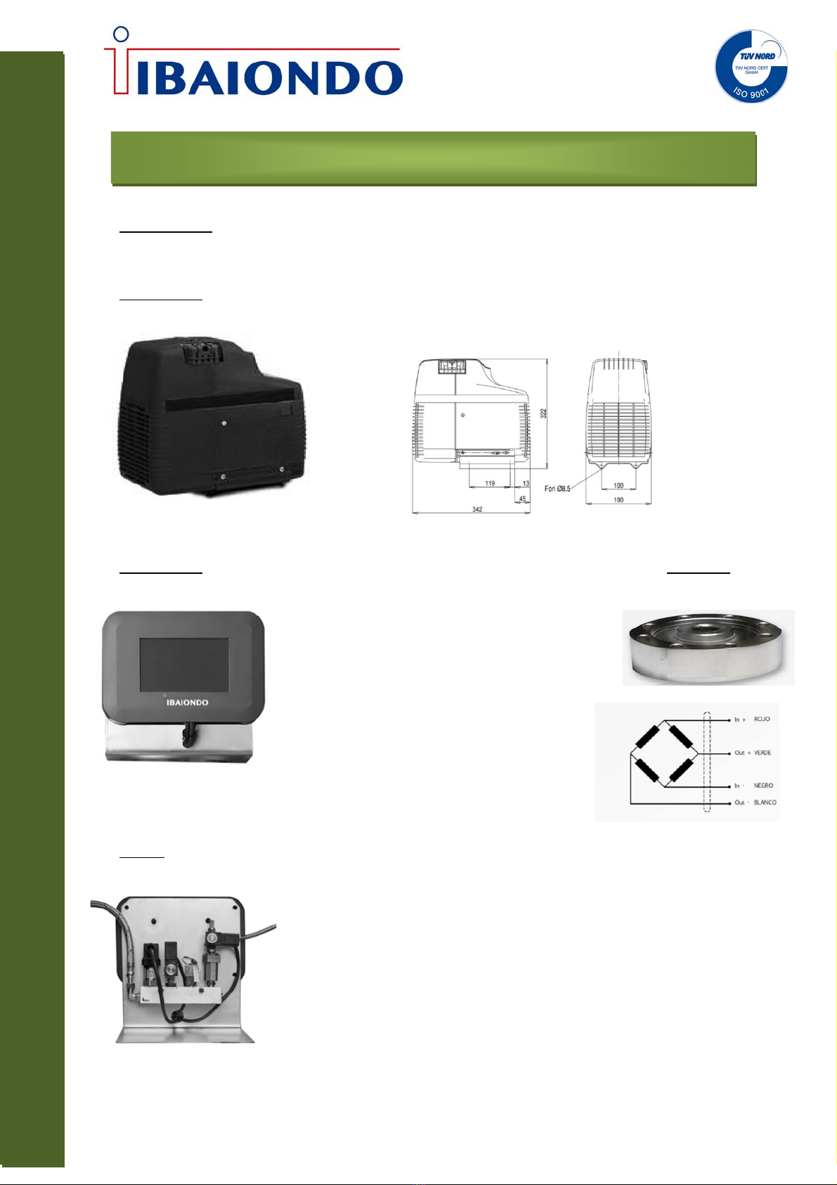
Control unit
Electronic board
The electronic board include de following elements:
Terminals for 230Vac power input
Magnetothermic protection 10A serie C
Microcontroller for the management and control of the equipment
Relay for the activation of the 230Vac 10A compressor with function check
Relay for the activation of the air solenoid valve 230Vac 10A with function check
Relay for the activation of the 230Vac 10A automatic filling solenoid valve with function check
Voltage alarm relay of 230Vac 10A potential-free
Pressure alarm relay 230Vac 10A potential-free
Analog input 4 - 20 mA of pressure measurement
Analog input 4 - 20 mV of volume / weight measurement (load cell)
Pressure output 4 - 20 mA mirror of the pressure input
Volume output 4 - 20 mA mirror volume / weight input
Connection with the touch screen
RS485 connection
Ethernet connection
Lithium battery for the maintenance of the hour
Connectors
Connector for the power supply (phase, neutral and ground)
DB9 connector for RS45 communication is connected (A, B, GND)
RJ45 female connector for Ethernet port
Connector of double row of 30 contacts whose connections are:
01: Analogue In Pressure -> +24VDC
02: Analogue In Pressure -> A
03: Analogue In Pressure -> B
04: Analogue In Volume/Weigth ->
+24VDC
05: Analogue In Volume/Weigth -> A
06: Analogue In Volume/Weigth -> B
07: Analogue Out Pressure -> Vref
08: Analogue Out Pressure -> A
09: Analogue Out Pressure -> B
10: Analogue Out Volume/Weight -> Vref
11: Analogue Out Volume/Weight -> A
12: Analogue Out Volume/Weight -> B
13: Digital In Water -> Signal
14: Digital In Water -> Ref (GND)
15: Auxiliar In -> Signal
16: Auxiliar In -> Ref (GND)
17: Pressure alarm Out -> A
18: Pressure alarm Out -> B
19: Volume/Weight alarm Out -> A
20: Volume/Weight alarm Out -> B
21: Alarm Out CPU -> A
22: Alarm Out CPU -> B
23: Auxiliar Out-> A
24: Auxiliar Out-> B
25: Compressor out -> Phase
26: Compressor out -> Zero
27: Solenoid valve air Out -> Phase
28: Solenoid valve air Out -> Zero
29: Solenoid valve autofilling -> Phase
30: Solenoid valve autofilling -> Zero