IBC INTERGAS DC Series Configuration guide

NOTE
These instructions are to be closely followed, and referenced to the
details in the boiler’s current certified Installation and Operating
Instruction Manual.
WARNING
For your safety, turn off electrical power supply at service panel and allow unit to cool before proceeding. Failure to do
so can cause severe personal injury or death. The ability to properly perform service on this equipment requires
certain expertise, mechanical skills, tools, and equipment. If you do not possess these, do not attempt to perform any
service on this equipment. A failure to follow this warning could result in possible damage to this equipment, serious
personal injury, or death.
NOTE
Installing and servicing boiler
equipment, parts and
accessories, can be
hazardous due to gas and
electrical components.
Only trained personnel
should install or service
heating equipment.
When working on boiler
equipment, observe
precautions in the literature,
on tags, and on labels
attached to the unit.
www.ibcboiler.comOctober 29, 2019 Page 1 of 2
Cleaning the DC and HC Series Heat Exchangers
Like any condensing appliance, the IBC DC- and HC-series boiler / water heaters must be regularly inspected and
maintained.
Part ofperforming an annual maintenance is being prepared to clean a heat exchanger when it’s required; buildup
from the products of combustion are typically concentrated on the bottom half of the heat exchanger where cooler
water has caused flue gases to condense.
How to Access the Heat Exchanger for Cleaning
1. Remove any call for heat, and power off the boiler / water heater.
2. Remove cabinet front door panel and allow the boiler to cool. There is no need to drain the boiler’s water unless
the boiler will be subject to freezing conditions while the boiler is off.
3. Lay a plastic barrier over the bottom of the boiler cabinet to protect the electronics beneath from water in the
condensate assembly and from spillage during the cleaning process.
4. Turn off the gas supply.
5. Disconnect the flue pipe from the condensate tray by rotating the nut counter-clockwise about ¼ turn. Slide the
flue pipe up and dis-engage the bottom of the flue pipe from the condensate tray and slide down to remove.
6. Unplug the electrical connectors at the gas valve and both connectors to the fan.
INSTRUCTIONAL
NOTE
Heat Exchanger Cleaning
DC / HC Series (all models)
Table 1: Heat Exchanger Service Kits by Boiler / Water heater model
HEAT EXCHANGER
SERVICE KIT PART # BOILER MODEL
DC Series – DC 23-84
HC Series – HC 13-50, HC 23-84
P-713
DC Series – DC 29-106
HC Series – HC 29-106
P-714
DC Series – DC 15-96, DC 33-124, DC 20-125, DC 33-160
HC Series – HC 15-96, HC 33-124, HC 20-125, HC 33-160
P-715
Figure 1: Heat Exchanger Gasket from P-715
7. Loosen the lower gas valve connection nut. NOTE:
There is an O-ring in the lower gas connection. Remove
the two 8mm nuts on the outlet of the fan; remove the
entire fan and gas valve assembly. Place this in a safe
location to be used for re-assembly. Cover the gas
piping connections to prevent debris from entering the
gas piping.
8. CAUTION: When removing the heat exchanger front
cover in step 9, be careful not to damage the burner
and refractory material located on the opposite side of
the heat exchanger cover. Use caution when handling
refractory materials. See CAUTION sidebar over.

Heat Exchanger Cleaning
DC / HC Series (all models)
www.ibcboiler.comOctober 29, 2019 Page 2 of 2
INSTRUCTIONAL
NOTE
The heat exchanger has a
small amount of combustion
chamber insulation
(refractory), which contains
ceramic fibers.
When exposed to extremely
high temperatures, the
ceramic fibers, which contain
crystalline silica, can be
converted into cristobalite -
which is classified as a
possible human carcinogen.
Care should be taken to
avoid disturbing or damaging
the refractory. If damage
occurs, contact the factory
for directions.
Avoid breathing and contact
with skin and eyes and follow
these precautions:
1. For conditions of frequent
use or heavy exposure,
respirator protection is
required. Refer to the
“NIOSH Guide to the
Selection and Use of
Particulate Respirators
Certified under 42 CFR 84"
for selection and use of
respirators certified by
NIOSH. For the most current
information, NIOSH can be
contacted at 1-800-356-4676
or on the web at
www.cdc.gov/niosh.
2. Wear long sleeved, loose
fitting clothing, gloves and
eyes protection.
3. Assure adequate
ventilation.
4. Wash with soap and water
after contact.
5. Wash potentially
contaminated clothes
separately from other
laundry and rinse washing
machine thoroughly.
6. Discard used insulation in
an air tight plastic bag.
NIOSH stated first aid:
• Eye contact - Irrigate and
wash immediately.
• Breathing - Provide fresh
air.
CAUTION
Any evidence that the front cover can no longer mate with the heat exchanger walls means that
the either the front cover or the heat exchanger must be replaced.
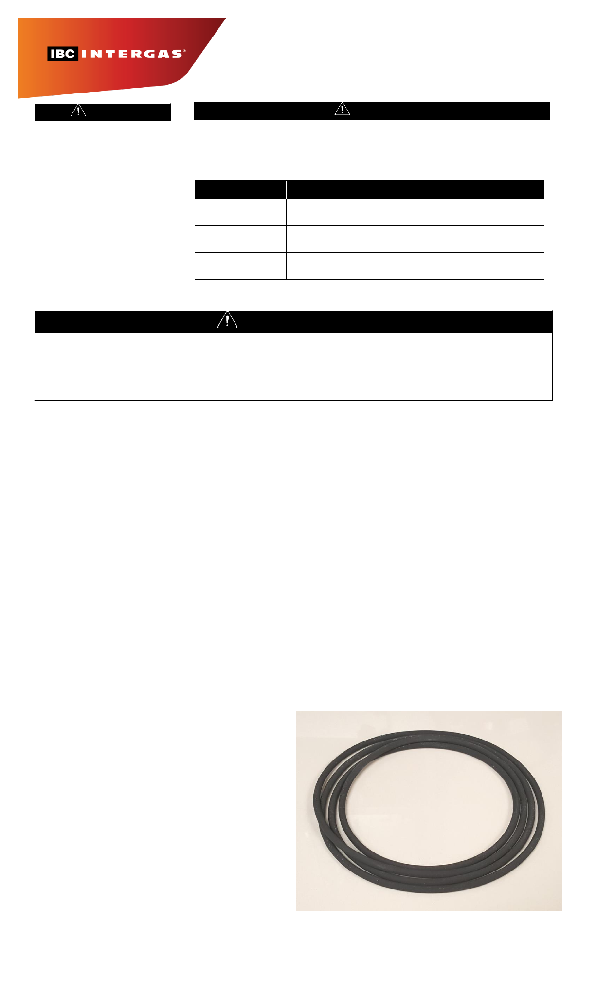
11. Peel heat exchanger gasket from its groove. See Fig. 3. Carefully inspect the gasket sealing
the heat exchanger to the heat exchanger cover for damage, hardness, cracks, and or
discoloration. If damaged in any way the gasket must be replaced.
12. Clean as necessary. IBC recommends cleaning with a stiff plastic brush, such as used for
scrubbing cooking pots. See Fig. 4. Wear protective gear such as eye protectors, gloves and a
particle mask. Care should be taken to protect the bottom of the boiler cabinet: drape a small
plastic sheet to gather debris from the cleaning. It is especially important to protect the lower
gas supply line from being fouled and the controller from getting wet.
When the heat exchanger is heavily fouled (see Fig. 5), a stiffer brush, scraper or implement may
be needed.
13. In some cases chemical intervention is also necessary; for heavily fouled heat exchangers,
contact your heating wholesaler for a cleaning solution approved for use on the gas side of an
aluminum heat exchangers, such as the two-solution process available from Axiom.
14. While the heat exchanger is open, carefully inspect the heat exchanger gasket for any signs of
discolouration, cracking or brittleness. Replace the gasket at the first signs of wear, at least
every two years, and every year in the case of heavy-use units.
Also inspect the burner, burner gasket, and ignitor.
Figure 2: 6mm Hex Bolts
Figure 5: Heavily fouled HX may require stiffer brush or tool.
How to Access the Heat
Exchanger for Cleaning
continued
9. Using a ball-ended 6mm hex key,
remove all bolts from the heat
exchanger front cover and carefully
remove the front cover, complete
with the fan attached.
10. Place the heat exchanger front
cover in a safe location. Inspect its
back surface for warpage,
especially at the top corners.
Figure 3: Removing a HX gasket
15. Reassemble in reverse order, or
see section 3.5.1 for detailed
instructions. Retighten HX bolts in
a cross pattern. Soap test all gas
connections.
Figure 4: Cleaning HX with a plastic brush.
This manual suits for next models
1
Table of contents
Other IBC INTERGAS Industrial Equipment manuals
Popular Industrial Equipment manuals by other brands

oventrop
oventrop Regudis W Installation passport

Wiedenmann
Wiedenmann Snow Master VARIO 3350 Series Translation of original operating instructions

ABB
ABB HT611632 Operation manual

Siemens
Siemens Sivacon S8 operating instructions

Sealey
Sealey BTR4.V2 instructions

EMUGE
EMUGE FRANKEN Softsynchro 6 Operating instruction