IBC INTERGAS SFC 16-125 User manual

120-245E-R1 |1
Note
IfconvertingfromNaturalGastoPropane,orderthePropaneconversionpartskit(IBCPart#P-806)fromyour
authorizedIBCdistributor.
UsetheNaturalGasconversionpartskitifthefuelsourceatthesiteusesNaturalGasandtheunithasbeensetup
(factoryfire-tested)tooperatewithPropane.Checktheratingplateontheunittoseewhichfuelsourcetheparticularunit
hasbeensetupwith.
Usingthisconversionkit,aqualifiedtechnicianwillneedto:
1. Performafuelconversion.
2. Performacombustiontest.
3. Fillintheinformationrequiredonthefuelconversionlabels,andaffixthemtotheunitaftertheconversionis
completed.
Warning
Thisconversionkitshallbeinstalledbyaqualifiedserviceagencyinaccordancewiththemanufacturer’s
instructionsandallapplicablecodesandrequirementsoftheauthorityhavingjurisdiction.Iftheinformationin
theseinstructionsisnotfollowedexactly,afire,anexplosionorproductionofcarbonmonoxidemayresult
causingpropertydamage,personalinjuryorlossoflife.
Thequalifiedserviceagencyisresponsiblefortheproperinstallationofthiskit.Theinstallationisnotproper
andcompleteuntiltheoperationoftheconvertedapplianceischeckedasspecifiedinthemanufacturer’s
instructionssuppliedwiththekit.
Theunitwillautomaticallyde-ratethemaximuminputatarateofapproximately2%per1,000’above4,500’.Thegas
valve'szero-governorwillensurethatthegas-airmixtureisnotaffectedataltitude.
Includedwiththeconversionkit:
1xOrifice-Marked450-IBCPart#180-228
1xO-ring-IBCPart#150-175
1xRatingPlateFuelOverlay-IBCPart#080-247
1xGasValveConversionLabel-IBCPart#080-107
1xInstallerIdentifierLabel-IBCPart#080-245
SFC 16-125 - Fuel Conversion to Natural
Gas (LP to NG) Kit P-807

Combustion Test Target Ranges
Figure 1 Gas valve and fan
TheLowFire(zero-offset)valveadjustmentcaponthegasvalvehasbeenfactoryset.Donotadjustthisscrewinthefield
unlessindicatedintheseinstructions.
Afterconvertingtheunittonaturalgas,acombustion(CO2)readingmustbetakenbyaqualifiedtechnicianusingproperly
functioningandcalibratedcombustionanalyzingequipmentandtheresultscomparedtothevaluesinTable1.
Natural Gas CO2 Value (%) at High Fire with front cover
open
CO2 Value (%) at Low Fire with front cover
open
Max.CO2value 10.1% ActualValueatHighFire
Min.CO2value 9.1% 9.1%
Table 1 Combustion test target ranges - CO2 / Maximum CO
2|

SFC 16-125 - Fuel Conversion to Natural Gas (LP to NG) Kit P-807 |3
Fuel Conversion Instructions
Thefollowingproceduremustbecarriedoutbyaqualifiedtechnician.
Model Number Orifice Size
SFC16-125 450
Table 2 Natural Gas Orifice Chart
Alternate Natural Gas Orifices - Calorific values 750-
900 BTU/FT3
Model Number Orifice Size
SFC16-125 490
Table 3 Alternative Naturel Gas Orifice - calorific values between 750-900 BTU/FT3
To perform a fuel conversion:
1. Turnoffthegassupplyatthemanualgasvalve.
2. Disconnecttheelectricalpower.
3. Disconnectthenutatthegasvalveoutlet(topofthegasvalve),andremovetheO-ringandorifice.
4. InsertthecorrectorificeintotheO-ring,andre-installintothenutatthegasvalveoutlet(topofthegasvalve),
andthentightenthenut.
5. Restorethegassupplybyopeningthegascontrolvalve.
6. Testforleaksbyusinganapprovedleakdetectionsolutiononalljoints.
7. Powerontheunit.
Now,carefullyfollowtheproceduresonCombustionTestingandAdjustment.

Combustion Testing and Adjustment
Danger
Acombustiontestchecksthatthegasvalveisoperatingproperlyinthefield.Toperformacombustiontest,you
mustbeaqualified,trainedandlicensedgasfitter.
Makingadjustmentstothegasvalvewithoutaproperlycalibratedgascombustionanalyzerandbypeoplewho
arenottrainedandexperiencedinitsuseisforbidden.Failuretouseananalyzercanresultinanimmediate
hazard.
Model Number High Fire Input
SFC16-125 125MBH
Table 4 Rated input of a converted unit
Normalignitionsystemsequenceofoperation:
Theunit'scontrol,uponacallforheatorDHW,turnsonthecombustionfanfora5-secondpre-purge,thenenergizesthe
sparkelectrodeandgasvalvefora5-secondtrialforignition.
Iftheburnerdoesnotlight,theprocessisrepeateduntiltheburnerlightsandflameisdetected.After4unsuccessfultrials
forignition,theunitlocksoutandwillneedtobemanuallyresetbypressingtheReturnArrow button.
To perform a combustion test and adjustment:
1. Turnofftheunit’smanualgasvalve.
2. WithaTorx15screwdriver,opentheinletgassupplypressuretestportbyturningits
screw1fullturncounterclockwise.
3. Attachamanometertotheinletpressuretestportandturnongastoappliance.
Staticmanometerreadingshouldbeideally11"w.c.forPropane.
Minimumandmaximumstaticpressuremustbebetween5"and14"w.c.
Monitorpressurethroughoutthecommissioning(start-up)procedure.
Pressuremaydroopupto1"w.c.athighfire.
4. Tosettheunittohighfiremanually,createalargeDHWdemandfortheunittoheat.:
Allowtheunittoignite/runagainstalargeload,tomaintainhighfire.Tosetthehigh-firemanually,pressandhold
theServiceiconfortwoseconds.ThenwhileholdingtheServiceiconpressthePlusbuttontwice.“H”willshowin
theservicedisplayastheunitentershighfire.
4|

SFC 16-125 - Fuel Conversion to Natural Gas (LP to NG) Kit P-807 |5
Note:AllowtheunittooperateatHighFirefor3minutestostabilize.(Theunitoperatesinmanualmodefor10
minutesthenswitchbacktothenormaloperatingmode.Toextendmanualmodeoperation,presstheService
andPlusbuttonstogethertwicewhiletheunitisoperatinginmanualmodetoresetthetimerfor10more
minutes.)Donotmakeadjustmentsiftheservicedisplayshowsan“h”.
5. Clockthegasmeter(seeinstructionsClocking the Meter (for Natural Gas only) on page 6)toconfirmfull
maximumratingplateinput.
a. Withacombustionanalyzerprobeinthefluegastestport,checkthemeasuredresultsagainstTable 1 -
HighFire.
b. Iftheresultsareoutsidethepermittedrange,checktheinletpressure,andconfirmthatthecorrectorificeis
installed.
6. SwitchthewaterheatertolowfirebypressingtheServicebuttonandMinusbuttonatthesametime.Thewater
heaterwilldroptolowfire.“L”willshowintheservicedisplay.
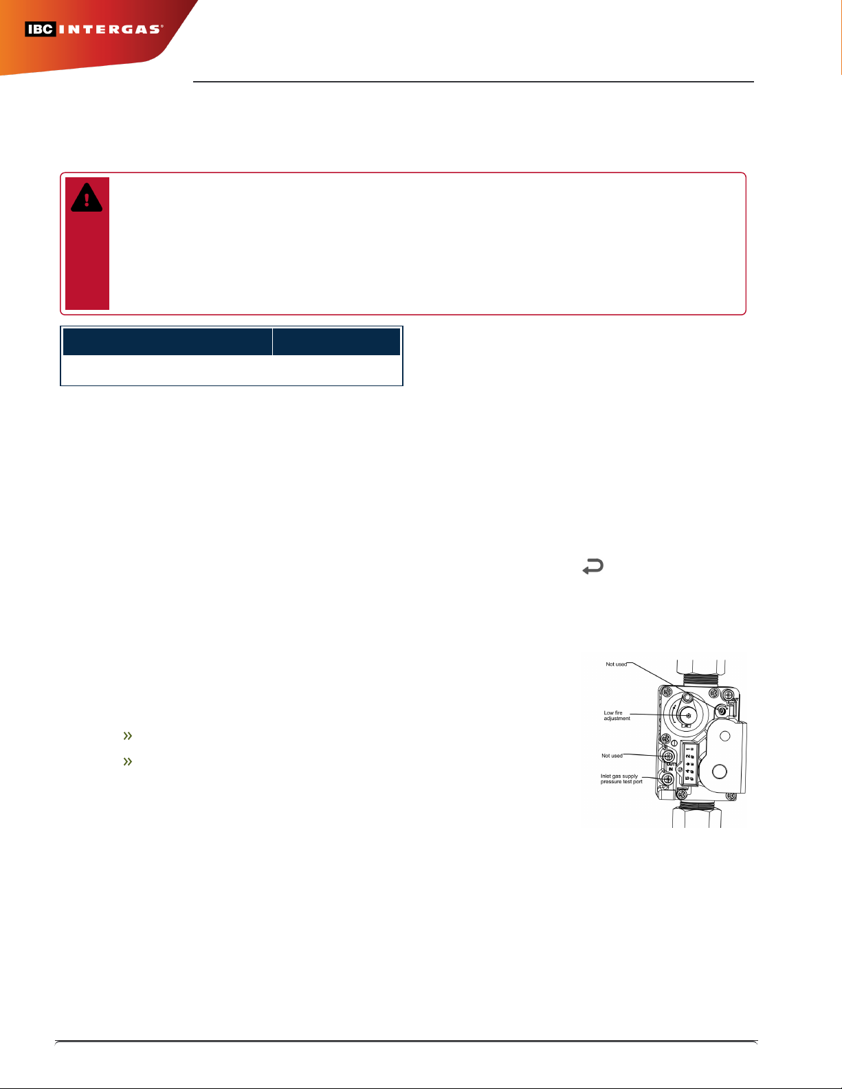
a. ComparethereadingswithTable 1 -LowFire.Ifadjustmentisnecessary,removetheLowFire
AdjustmentcaptorevealaTorxheadscrew.
b. Maketinyadjustments,typicallylessthan1/8thofaturnatatime.Turnthescrewclockwisetoincrease
CO2andcounter-clockwisetoreduceCO2.Ifthetargetcannotbemet,evenafterahalfturn,contactthe
factory.
c. Whenfinished,replacetheLowFirecap,andleavethemanualmodebypressing+AND-
simultaneously.
7. Switchofftheunitbypressingthespaceabovethedot.
8. Turnoffthegasattheunit'smanualgasvalve.
9. Removethefluegasanalyzerfromthetestport,andreinstallthetestportcap.
10. Removethegaspressuremanometerfromthegasvalve,andfullyclosethetestport.
11. Turnonthegasattheunit’smanualgasvalve.
12. Ensuretherearenogasleaksbeforereinstallingthefrontcover.
13. Turnontheunitbypressingthespaceabovethedot.
Completing and Affixing the Conversion Labels
1. Fillintheconversionlabels(includedinthekit)associatedwiththenewfueltype.
2. Placetheconversionlabelsontotheunitatthepositionsindicatedonthelastpage.

Clocking the Meter (for Natural Gas only)
1. Turnoffallotherappliancesandpilots
2. Turnontheunitandsettheunittohighfire.
3. Ensuretheunithasalargeloadtoheat,sothattheunitwillnotshutoff.
4. WithaStop-Watch,recordthenumberofsecondsforthesmallestdialtomake1fullrevolution.
5. CFH=(3600xDialSize)/Seconds
6. CFHx1000(checklocalBtucontent)=InputBtu’s.
Note
For2PSImetersmultiplyCFHx1.097
ForMetricmetersmultiplyCFHx35.3
For2PSImetricmetersmultiplyCFHx1.097x35.3
ForAltitudeabove4,500'deduct2%per1,000’ofaltitudefromtheInputBtu’s.
6|

SFC 16-125 - Fuel Conversion to Natural Gas (LP to NG) Kit P-807 |7
Where to Place Conversion Labels on the Unit
Table of contents
Other IBC INTERGAS Industrial Equipment manuals
Popular Industrial Equipment manuals by other brands

ITOH DENKI
ITOH DENKI POWER MOLLER IB-P03 Technical documentation

DUSTLESS BLASTING
DUSTLESS BLASTING DB800 MOBILE user manual

KNECHT
KNECHT HV 205-1 operating instructions

ABB
ABB Power2 845-M46 Operation manual

Evenheat
Evenheat Glass Kiln GTS 18 General operations manual

Stoll
Stoll CMS 933 operating instructions