IBEA 25 - L User manual

I
GB
MANUAL DE INSTRUCCIONES
MOD.25 - L / B
MOD.29 - L / B / MUL
MANUALE D’ISTRUZIONE
F
OWNER’S MANUAL
MANUEL D’INSTRUCTION
GEBRAUCHSANWEISUNG
PMANUAL DE INSTRUÇÕES
BRUKSANVISNING
D
S
E
NL INSTRUCTIEHANDLEIDING

2
FIG.2 FIG.3 FIG.4
FIG.5 FIG.6 FIG.7
FIG.8 FIG.9 FIG.10
FIG.13 FIG.14 FIG.15

3
FIG.16 FIG.17 FIG.18
FIG.19 FIG.20 FIG.21
FIG.22 FIG.23 FIG.24
FIG.25 FIG.26 FIG.27

Caro cliente, la ringraziamo vivamente per aver scelto un prodotto di qualità della ditta IBEA.
Per un corretto impiego del decespugliatore e per evitare incidenti, non iniziate il lavoro senza aver letto questo manuale con
attenzione. Troverete su questo manuale le spiegazioni di funzionamento dei vari componenti e le istruzioni per i necessari
controlli e per la manutenzione.
N.B. : La casa produttrice si riserva la possibilità di apportare eventuali modifiche in qualsiasi momento e senza preavviso.
(INDICE PAG.6)
INTRODUZIONE
F
GB INTRODUCTION
Dear customer, thank you very much for having chosen a quality product of the company IBEA.
For proper use of brush-saws and to avoid accidents, do not start work without having read the manual carefully.You’ll find this
guide on the explanations of operation of various components and instructions for the necessary inspections and maintenance.
N.B. : The manufacturer reserves the right to make changes at any time without notice.
(CONTENTS PAG. 13)
Cher client, je vous remercie beaucoup d’avoir choisi un produit de qualité de la société IBEA.
Pour un bon usage de la brosse-scies et pour éviter les accidents, il ne faut pas commencer à travailler sans avoir lu le manuel
attentivement.Vous trouverez ce guide sur les explications du fonctionnement de divers composants et des instructions pour les
inspections nécessaires et de l’entretien.
N.B. : Le fabricant se réserve le droit d’apporter des changements à tout moment sans préavis.
(INDEX PAG. 20)
INTRODUCTION
EINTRODUCCIÓN
Estimado cliente, muchas gracias por haber elegido un producto de calidad de la empresa IBEA.
Para un buen uso de la brocha-y las sierras para evitar accidentes, no debemos empezar a trabajar sin haber leído el manual
cuidadosamente. Va a encontrar esta guía en las explicaciones de cómo los diversos componentes y las instrucciones para el
mantenimiento y las inspecciones necesarias.
N.B : El fabricante se reserva el derecho a realizar cambios en cualquier momento sin previo aviso.
(ÍNDICE.PAG.26)
I

D
Geehrter Kunde, wir danken Ihnen, dass Sie ein Qualitätsprodukt der Firma IBEA gewählt haben.
Zur korrekten Verwendung der Heckenschere und zur Vermeidung von Unfällen muss vor dem Beginn der Arbeiten diese
Gebrauchsanweisung aufmerksam durchgelesen werden. In dieser Gebrauchsanweisung finden Sie die Erklärungen für den
Betrieb der verschiedenen Bauteile und dieAnweisungen für die erforderlichen Kontrollen und Wartungsarbeiten.
N.B.:Der Hersteller behält sich das Rech vor, jederzeit und ohne Vorankündigungen irgendwelche Änderungen vorzunehmen.
(INHALTSVERZEICHNIS S.34)
EINLEITUNG
Prezado cliente, agradecemos-lhe por ter escolhido um produto de qualidade da empresa IBEA.
Para uma utilização correcta da máquina corta-mato e para evitar acidente, não começe o trabalho se ter lido este manual com
atenção. Encontrará neste manual as explicações de funcionamento dos vários componentes e as instruções para os controlos
necessários e para a manutenção.
OBS :A casa produtora reserva-se a possibilidade de efetuar eventuais alterações em qualquer momento e sem aviso prévio.
(ÍNDICEPÁG.41)
INTRODUÇÃO
P
Beste cliënt, we danken u dat u voor een IBEA kwaliteitsproduct gekozen heeft.
Vang de werkzaamheden nooit aan voordat u deze handleiding aandachtig doorgelezen heeft om een correcte gebruik van de
bosmaaiermogelijk te maken en ongevallen tevermijden. Deze handleiding bevat informatie betreffendede functionering van de
verschillende componenten en aanwijzingen voor de noodzakelijke controles en onderhoudswerkzaamheden.
N.B. : De producent behoudt zich het recht om zonder mededeling op elk gewenst moment wijzigingen door te voeren.
(INHOUDSOPGAVEPAG.48)
INLEIDING
NL
S
Bäste Kund, tack för att Du har valt en kvalitetsprodukt från företaget IBEA.
För att kunna använda busktrimmern på ett korrekt sätt och förhindra olyckor är det viktigt att den inte tas i bruk förrän du
noggrant har läst igenom denna handbok. I handboken finns förklaringar till de olika komponenternas funktioner och
instruktionerna för de nödvändiga kontrollerna och för underhållet.
OBS! Tillverkaren förbehåller sig rätten att göra ändringar på produkten utan att från gång till gång anpassa innehållet i
handboken.
(INNEHÅLLSFÖRTECKNINGSIDA. 55)
INLEDNING

IITALIANO
6
INDICE
1.Spiegazionesimboli............................................................................................................................................................................Pag. 5
2.Perla vostrasicurezza.................................................................................................................................................................................5
3.Descrizionedelle parti.................................................................................................................................................................................6
4.Datitecnici eDichiarazione diconformità................................................................................................................................................7
5.Assemblaggio...............................................................................................................................................................................................8
6.Normed’uso.................................................................................................................................................................................................9
7.Preparazioneall’uso..................................................................................................................................................................................10
8.Manutenzioneperiodica...........................................................................................................................................................................10
9.Rimesaggio..................................................................................................................................................................................................11
10.Certificatodi garanzia..............................................................................................................................................................................11
1.SPIEGAZIONESIMBOLI
Avvertenza,pericoloed attenzione.
Leggereil manuale diuso e manutenzione
prima di utilizzare questa macchina.
Indossaredispositivi diprotezione durante ilfunzionamento
di questa macchina.
2.PERLAVOSTRASICUREZZA
12-Accertarsiche laprotezione deldisco odella testina e
gli altri dispositivi siano montati correttamente e salda-
mente.
1-Leggereattentamentequeste istruzionied accertarsidi
comprenderle prima di far funzionare I’unità.Attenersi a
tuttele avvertenzeed alleistruzioni disicurezza. Conser-
varequesto manualea titolo difuturo riferimento.
2-Usaresolamentericambioriginali,pezzidiricambio pro-
dottida altri fabbricanti potrebbero adattarsimale e cau-
sare lesioni .
3-
Indossareabitiadattied articolidisicurezzaquali
:stivali,pan-
taloni robusti, guanti, visiera o occhiali protettivi, cuffia e
cascoprotettivo.
4-Nonindossare articolid'abbigliamento poco aderentio
slacciati.
5-Non permettere ad altre persone, bambini o animali di
restare nel raggio di 15 m. durante I’uso del
decespugliatore.
6-Non operare con il decespugliatore quando si è stan-
chi, malati o sotto I’effetto di alcool, droghe o farmaci.
7-Nonpermettereai ragazzidi usareun decespugliatore.
8-Mantenersi ben saldi ed in equilibrio. Mantenere il di-
spositivo di taglio al di sotto dell’altezza della cintura.
9-Usareildecespugliatore solamente percompiti indicati
dalpresente manuale.
10-Ispezionarela macchina prima di ogni impiego.Con-
trollareche laleva acceleratore funzionibene.Accertarsi
che il disco sia libero di girare e non sia a contatto con
corpiestranei, che nonci sianoperdite dicarburante, che
idispositivi di sicurezzanon sianoallentati ecc..Sostituire
leparti danneggiate.
11-Avviareil decespugliatoresolo inluoghi benventilati, i
gas di scarico, se respirati, possono causare una asfis-
siamortale.
copri disco montato.
14-Usare esclusivamente il filo di nylon o il disco racco-
mandatodal fabbricante,per esempionon usarein alcun
modofili dimetallo ocorde rinforzatein metallo,visto che
potrebberorompersi eformare proiettilipericolosi.
15-Conilmotore inmoto non farealcuna manutenzionee
non toccare il disco.
16-Una volta spento il motore, prima di appoggiare per
terra l‘unità accertarsi che il dispositivo di taglio si sia
arrestato.
17-Arrestareil motoree lasciarlo raffreddareprima delri-
fornimento.Riempireil serbatoiolontanoda fontidicalore
enonfumare duranteil rifornimentoo lamiscelazione del
carburante.
18-Nontogliereiltappodelserbatoioconilmotoreinmoto.
19-Asciugareilcarburante eventualmenterovesciato sul-
la macchina. Spostare il decespugliatore di 3 metri dal
punto
di rifornimento prima di mettere in moto il motore.
20-Nonusare carburanteper operazioni dipulizia.
21-Noncontrollare la scintilla dellacandela vicino al foro
dellacandela.
22-Nonlavorarecon unamarmitta danneggiata.
23-Primadell ‘uso deldecespugliatore, liberare I’areada
tosare da tutti gli oggetti: quali sassi, pezzi di vetro, filo
24-Prima di riporre in magazzino il decespugliatore, la-
sciareraffreddare il motoree svuotare ilserbatoio di car-
burante.
Tenerele persone
lontane 15 mt.
Farfallaariaaperta,
funzionamento
Farfallaaria chiusa,
13-Trasportareil decespugliatorea motorefermo e conil
25-Riporreil decespugliatore in mododa prevenire le le-
sioni accidentali causate da oggetti taglienti, lontano da
fontidi calore e sollevato dal suolo.
26-Non avviare il motore senza il braccio (trasmissione)
montato.

I
ITALIANO
7
27-Assicurarsi che il dispositivo di taglio sia stato instal-
lato correttamente e che sia ben stretto.
28-Sostituirela testina oil disco seapparissero incrinati,
scheggiatio danneggiati in qualsiasimodo.
29-Indossarei guantiper maneggiare oeffettuare lama-
nutenzionedella lama.
30-Con il motore al minimo il disco non deve girare. In
casocontrario regolare la vitedel minimo.
31-Trasportareildecespugliatore amotore fermoe conil
copri disco montato.
33-Usare sempre le lame affilate,una lama senza filo ha
mag-gior probabilità di bloccarsi ecausare contraccolpi.
Sostituire i dischi che abbiano perso il filo.
NONCERCARE diaffilarli.
34-E’necessario arrestareil motoreed esaminareil disco
tutte le volte che si colpisce un oggetto duro.
35-Gliattrezzi dataglio oppuregli accessori usatidovran-
no essere originali IBEA oppure essere espressamente
approvatiper I'applicazione alpresente modello.
36-Quando viene applicato il disco per il taglio del legno,
montare la protezione disco specifica .
3.DESCRIZIONEDELLE PARTI
1.Interruttore diarresto (STOP)
2.Levaacceleratore
3.Semi acceleratore
4.Levettafarfallaaria(STARTER)
5.Serbatoio carburante
6.Tapposerbatoiocarburante
7.Primer (spurgodel carburatore)
8.Impugnaturaavviamentomotore
9. Filtro aria
10.Impugnaturaanteriore
11. Barra di protezioneper l’utilizzatore
12.Attaccocinghiaggio
15. Protezione di sicurezza
17.Coppia conica
18. Testina a filo di nylon
19. Tubodi trasmissione
Solo per modelli EVOLUTION:
13. Tubodi trasmissione
14. Giuntoaccoppiamento accessori
16.Albero di trasmissione
ACCESSORIARICHIESTA:
A.Potatore angolato35°
B.Tagliasiepi
C.Potatore dritto

IITALIANO
8
4.DATITECNICIE DICHIARAZIONE DICONFORMITA’
ACTIVE s.r.l. Via Delmoncello 12 - 26037 San Giovanni in Croce (CR)
dichiara sotto la propria responsabilità che le macchine a marchio IBEA:
MODELLO IBEA
CILINDRATAcm³
POTENZA Kw /CV
CARBURATORE
ACCENSIONE
CAPACITA'SERB. CARB.
FRIZIONE
SISTEMA ANTIVIBRAZIONE
MANUBRIO/IMPUGNATURA
ACCELERATORE
TUBOTRASMISSIONE
PESOKg.
25 / L
IMPUGNATURA IMPUGNATURA
24.5
1.03 / 1.4
28.5
1.25 / 1.7
AMEMBRANAWALBROPRIMERTYPE
ELETTRONICA
DISPOSITIVODISICUREZZACONSGANCIOAUTOMATICO
25 / EVO
0.5 L
tra motore e trasmissione
4.8 kg 5.3 kg
Diametro54mm
Ø 24 Ø 26
Ø 26 Ø 24
4.8 kg 5.3 kg
sono conformi ai requisiti stabiliti dalle direttive:
25 / B 29 / L 29 / EVO 29 / B
MANUBRIO MANUBRIO
Ø 24 Ø 24
5.3 kg 5.3 kg
Euro 1 Euro 1Euro 2 Euro 2
FINOALNUMERODISERIE
DIRETTIVE
DALNUMERODISERIE
25XX9999
MODELLO 25 L - 25 EVOLUTION - 25 B 29 L - 29 EVOLUTION - 29 B
E25XX0001
29XX9999
E29XX0001
2006/42/CE - 2004/108/CE - 2000/14/CE - 2002/44/CE
(Allegato V)
2012/46/CE
(Allegato VI) 2012/46/CE
(Allegato VI)
MODELLO ATTREZZO LIVELLOPRESSIONE
ACUSTICA
(ENISO 22868)
LIVELLOPOTENZA
ACUSTICA
(ENISO 22868)
LIVELLOVIBRAZIONI (m/s²)
(UNIENISO22867)
Impugnatura
DX SX
25 L - Evolution
29 L - Evolution 90 dB (A)
99 dB (A)
103 dB (A)
110 dB (A)
5
5,1
4,7
4,9
25 B
29 B
90 dB (A)
99 dB (A)
103 dB (A)
110 dB (A)
4,3
4,5
4,1
4,3
Ladocumentazione tecnica è depositatainDirezione Tecnica.
ALBERTOGRIFFINI
PRESIDENTE
ACTIVE S.r.l.
Via Delmoncello, 12
26037 San Giovanni in Croce (CR) - ITALY
01/03/2014

I
ITALIANO
9
5.ASSEMBLAGGIO
-Assicurarsi che la flangia superiore (5) sia posizionata
correttamente. Montare la lama assicurarsi che sia cen-
tratasullaflangia (5).Assicurarsi delgiusto sensodi rota-
zione(scritte o freccia didirezione rivolte verso l'altocon
macchinain posizione dilavoro).
- Montare la flangia inferiore (3), coppetta di protezione
(2)-(se laflangia inferioreèsprovvista diprotezione peril
dado), avvitare il dado (1) in senso antiorario a Kgm 3.0
(30Nm).
-Per bloccare il dado (1), girare la lamasino a che il foro
dellaflangiasuperiore corrispondaconil forodella coppia
conica,edinserirelachiavea brugolaindotazione(4mm),
(Fig.8)
-Montare la testinaa fili di nylonseguendo la disposizio-
ne illustrata: Flangia superiore, testina a fili di nylon.
(Fig.9)
Serratea mano in sensoantiorario
dopo aver inserito la chiave a brugola (4 mm) nel
foro3 della coppia conica.
Per la vostra sicurezza utilizzare lame originali
ACCESORIARICHIESTA(Mod. EVO).
A-POTATOREANGOLATO35°
B-TAGLIASIEPI
C-POTATOREDRITTO
MONTAGGIO DEGLIACCESSORIO (A- B - C) SULLA
MACCHINAFig.26
-Allentare,insenso antiorario, la leva(1)
-Infilare il tubo (2),fino al riferimento (3)circa 40mm, nel
manicotto (4) tenendo il piolino (7) spostato verso l'alto,
per facilitare l’inserimento dell’albero (5) nel mozzo del-
l’albero(6), ruotare l’attrezzoun poco adestra e un poco
a sinistra fino a che l’attrezzo/tubo sia inserito corretta-
mente.
- Ruotare l’attrezzo nella posizione di lavoro e bloccarlo
tramitela leva(1). Perla sicurezza dell'operatoreil tubo2
presentaun forodove deve inserirsiil piolino 7.
MONTAGGIODELLAPROLUNGA(a richiestae SOLO
PER GLIATTREZZIA- B - C)
Accopiamento prolunga - macchina fig.27:
-Allentare,in sensoantiorario, la leva (1).
- Infilare il tubo (2) della prolunga fino al riferimento (3),
circa40mm., nel manicotto (4) tenendo il piolino 12 spo-
stato verso l'alto. Ruotare il manicotto (10) nella stessa
posizione che il manicotto (4) e bloccarlo tramite la leva
(1).
Perlasicurezza dell'operatoreil tubo2 e8presentano un
forodove deveinserirsi ilpiolino 12.
Accopiamento accessorio - prolunga fig.27:
-Allentare,insenso antiorario, la leva(7)
- Infilare il tubo (8) dell’accessorio fino al riferimento (9),
circa40mm.,nel manicotto(10).Per facilitarel’inserimen-
todell’albero (11) ruotarel’attrezzoun pocoa destra eun
poco a sinistra fino a che l’attrezzo/tubo sia inserito cor-
rettamente.
ATTENZIONE: per l’utilizzo degli accessori
A - B - C vedi il manuale d’istruzione specifico
allegato ad ogni accessorio.
L’estensione della macchina (solo con gli accessori
A - B e D) non può superare i 1500mm., altrimenti è
pericoloso. Si può utilizzare una sola prolunga, la
750mm o la 1500mm.
MONTAGGIOMOTORETRASMISSIONE
-Assemblareil motore (1) allatrasmissione (2) e fissarlo
tramitele viti(3) (vedi fugura2).
Accertarsi che l'albero e il tubo della trasmissione
siano inseriti correttamente.
MONTAGGIO FILO ACCELERATORE E CAVI ELET-
TRICI Fig. 3
-Introdurre il cavo acceleratore (A)attraverso il tenditore
(B).Assicurarsi chela guaina(C)del cavoappoggi contro
l'internodel tenditore(B).Accertarsichela levaaccelera-
tore non sia bloccata in semi accelerazione quindi ag-
ganciareil terminaledel cavo nelmorsetto (E). Regolare
la tensione del cavo (A) allentando il controdado (D) e
girandoil tenditore (B), raggiungendo la giusta tensione,
stringere il controdado (D). Se la regolazione é corretta,
la leva acceleratore avrà un gioco libero di circa 2mm.
primache si muovala leva carburatore(E).
- collegare i cavi elettrici (F - G) Fig. 3
MONTAGGIO IMPUGNATURA (L) FIG.4 / MANUBRIO
Fig. 10
Fig.4-Togliereleviti (1)ed allargarel’impugnatura perin-
filarla nel tubo (3) e fissarla tramite le viti (1) e i dadi (4).
Posizionare la barriera di sicurezza (5) nell’apposito
alloggiamentoe fissarla tramite lavite (6) e dado (7).
Fig.10-Posizionare i 2 mezzi manubri(A-B) nel supporto
(D), assicurandosi che i terminali siano posizionati nella
gola (C) (vedi freccia), fissarli tramite il coperchio (E), le
viti (F) e i dadi (G).
La posizione dell'impugnatura sono registrabili secondo
leesigenzedell'operatore.
MONTAGGIO LAMETTATAGLIAFILO Fig. 5
Laposizione correttadella lametta tagliafiloè quellaindi-
cata nella figura 5 con la letteraA.
Utilizzare le viti ed i dati forniti in dotazione:
n°2 viti a brugola M5 x 14
n°2dadi autobloccanti M5
n°2rondelle M5
MONTAGGIO PROTEZIONE DISICUREZZAFig. 6
Fissare il cavallotto (6) sulla coppia conica (5) tramite la
vite(1).Applicare laprotezione (8)sul tubo ditrasmissio-
ne (4) e fissarla tramite il cavallotto (6), la vite (2) la ron-
della (3) e il dado (7).
IMPORTANTE:Assicurarsi che il cavallotto (6) sia
fissato sulla coppia conica (5) tramite la rondella e
la vite (1). Per ragioni di sicurezza le lame a sega non si
possono utilizzare con la protezione in dotazione. Non
cambiarela posizione dell'attrezzo di taglio.
MONTAGGIO LAMA E TESTA A FILI Dl NYLON
Fig. 7-8-9
- Fig. 7 Svitare in senso orario il dado (1); togliere la
coppetta (2) ( se la flangia (3) è sprovvista di protezione
per il dado ), e la flangia (3).
Montarela lama(4) seguendola disposizioneillustrata in
(Fig.8).

IITALIANO
10
6. NORME D'USO
ATTENZIONE: Primadi usareil decespugliatoreleggere
attentamente le norme di sicurezza.
Siraccomanda diusare ildecespugliatore dallaparte de-
stra del corpo (Fig.26), si dà così la possibilità ai gas di
scaricodiuscireliberamentesenza venirostruitidagliabiti
dell’operatore.Se sietenuovi all’uso deldecespugliatore
seguite il primo periodo di addestramento. Ispezionare
sempre attentamente la macchina prima dell’uso. Verifi-
care che non vi siano viti allentate, parti danneggiate e
perditedi carburante.Controllate periodicamente lecon-
dizioni del sistema antivibrante. Evitate un uso del
decespugliatore eccessivamente prolungato, le vi-
brazioni possono essere dannose. Primadi ogniutiliz-
zorimuovete dall‘areainteressata: pietre,vetri, funi, parti
metallichee tutti i corpiestranei che potrebbero aggrovi-
gliarsisullepartirotantioessereproiettatipericolosamente
a distanza. Indossare il cinghiaggio e agganciare il
decespugliatore.Tenere sempre entrambe le mani sulle
impugnatureduranteilfunzionamentodeldecespugliatore
Fig.26. Utilizzare ildecespugliatore come illustrato nella
Fig.16. Perfacilitare l‘operazionedi taglioe perragioni di
sicurezza, posizionare sempre il fermo della protezione
contro il materiale da tagliare. Verificare sempre che il
disconon subiscaincrinature dopourti accidentalicontro
oggetti estranei. Sostituire gli accessori ( dischi, testine
afilo ,protezioni, cinghiaggi) eventualmentedanneggiati
oeccessivamente usurati.
Fig. 15 Testina a fili di NYLON ACTIVE®. Il dispositivo
ACTIVEconsente il caricamentodel filo senza smontare
la testina(è un brevettoACTIVE).
- Usare sempre lo stesso diametro del filo originale per
nonsovraccaricare ilmotore.
-Spegnere ilmotore. Indossare iguanti di lavoro.
Ruotare,insenso orario,il pomolo(1) finoa chelafreccia
(2) del pomolo sia allineata con una delle boccole (6).
-Inserire il tubo (4) indotazione attraverso la testina.
- Infilare il filo e togliere il tubo.
Congiungere le estremità del filo e tirare il filo in modo di
avere i due rami del filo della stessa lunghezza.
- Ruotare il pomolo in senso orario, avendo cura di ten-
dere i due rami del filo ogni 3 giri, fino al completo
avvolgimento.
SMONTAGGIODELLATESTINA
Premereil pomolo(1).Contemporaneamentepremere
lalinguetta(5)edestrarreparzialmenteilcoperchio(7)dal
corpo della testina .Mantenendo il pomolo premuto,
premerel’altralinguettaedestrarreilcoperchio.
ASSEMBLAGGIODELLATESTINA
Montare le boccole (6) nella loro sede del coperchio (7).
Montare il rocchetto nel coperchio (7). Posizionare la
molla sul rocchetto oppure all’interno del corpo della
testina.
Montare il coperchio/rocchetto/boccole nel corpo della
testinaassicurandosi chele linguette (5)siano nella loro
sede.
FUNZIONAMENTO
Perallungareilfilo:fargirarelatestinamantenendoilmotore
accelerato.Battere al suolo il pomolo (1). Ogni scatto
corrisponde a circa 3 cm. di fuoriuscita del filo.
Nota:non battere la testina su superfici dure puòessere
pericoloso.
OPERAZIONIPRELIMINARI
Regolazione del cinghiaggio e della posizione del
decespugliatore. Indossare il cinghiaggio agganciare il
decespugliatoreal cinghiaggio tramiteil gancio. Posizio-
nare la fibbia per ottenere la corretta altezza del
decespugliatore.
CARBURANTE
ATTENZIONEildecespugliatoreèequipaggiatodaunmo-
tore2tempi, quindisi deveutilizzare esclusivamentecar-
burante miscelato con olio.
Prepararesolola miscelanecessaria all’uso.Non fumare
ed eseguire il rifornimento carburante sempre a motore
spento e lontano da fiamme. Usare carburante con nu-
mero di ottani non inferiore a 90. Miscelate la benzina
con olio sintetico con il rapporto 50:1 (2%). Se non
avete l’olio sintetico usare eclusivamente olio per
motori 2 tempi nella proporzione di 25:1 (4%).
Fig. 17
Importante: Mescolate fortemente e a lungo la tanica,
questa operazione deve essere accuratamente ripetuta
ognivoltache siprelevacarburante dallatanica.Le carat-
teristichedella miscela sono soggettead invecchiamen-
toe quindi si alteranonel tempo. Non usatemiscela pre-
paratada piùsettimane, sipotrebbero verificare danni al
motore. Riempire il serbatoio miscela solo per 3/4 per
permettereI’espansione della stessa.
RIFORNIMENTO
ATTENZIONEllrifornimentodeve essereeffettuatoamo-
torespento. Svitarelentamente il tappodel serbatoioper
lasciarefuoriuscire I’eventualeeccesso di pressione.
Dopoilrifornimentoserrare correttamenteiltappodel ser-
batoio. Spostare il decespugliatore di almeno 3 m. dal
punto di rifornimento prima di mettere in moto il motore.
Primadelrifornimentopulireaccuratamenteintornoal tap-
po del serbatoio. La sporcizia all’interno del serbatoio
causa problemi di funzionamento al motore.Assicurarsi
che la miscela sia omogenea agitando la tanica o il ser-
batoio.
AVVIAMENTO Fig. 19 - 23
Appoggiareil decespugliatore su diuna superficie piana
e sgombra e verificare che I’attrezzo di taglio sia libe-
ro di girare.
PortareI’interruttore sulla posizione(1) fig. 19.
Premere il bulbo (2) 5 o 6 volte fig. 23.
Portarela leva dello starter (1) in posizione chiusa (A)
fig.23.
Tenendofermoil decespugliatoretirarel’avviamentoed ai
primiscoppidel motoreriportare laleva starternella posi-
zioneoriginale aperta(B).
Ripeterelamanovrad'avviamentofinchèilmotorenonpar-
te. Amotoreavviato,premereI’acceleratore (2)persbloc-
carlodallaposizionedi semiaccelerazioneeportareil mo-
tore al minimo fig. 19.
ATTENZIONE:quandoilmotoreè giàcaldo,nonpremere
il bulbo (2) , non usare lo starter per I’avviamento. Non
rilasciarelacorda d’avviamento,ciòpotrebbe danneggia-
reilgruppoavviamento.
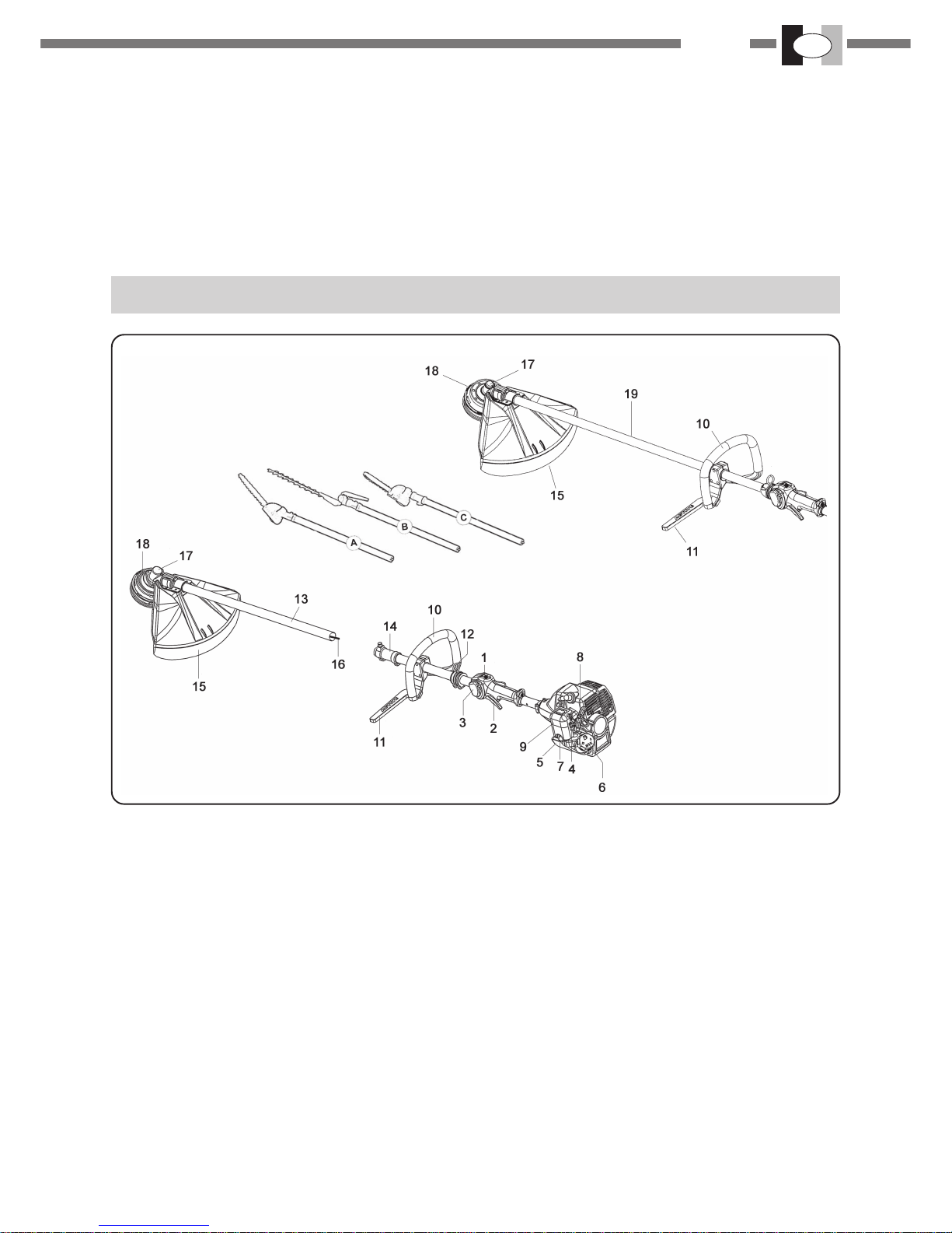
7.PREPARAZIONEALL'USO

I
ITALIANO
11
8.MANUTENZIONEPERIODICA
Controllare periodicamente che tutte le viti del
decespugliatore siano nelle loro sedi e ben serrate. So-
stituirele lame danneggiate, usurate,criccate e non pia-
ne.Verificare sempreil correttomontaggiodella testinaa
fili di nylon o la lama e che la vite che blocca la lama sia
benserrata.
FILTRO ARIA Fig. 18 - 24 - 25
-Verificare periodicamenteil filtro d'aria infunzione delle
condizionidilavoro
-Togliere ilcoperchio (B)
-Togliere il filtro(C)
- Pulire il filtro (C) con miscela di benzina / olio e strizza-
telo
- Mettere tassativamente l’olio sul filtro (C)
-Controllare le parti e se necessariosostituirle. Montare
insenso inverso allosmontaggio.
ATTENZIONE : Per migliori risultati e una lunga du-
rata, si raccomanda di utilizzare olio per filtri.
FILTRO CARBURANTE Fig. 20
Per la pulizia o per la sostituzione, togliere il tappo dal
serbatoioedestrarre ilfiltro(2) servendosidiun gancio(3)
o di una pinza a becchi lunghi.
Verificare periodicamente le condizioni del filtro; in caso
disporcizia eccessiva, provvederealla sua sostituzione.
MOTORE
Regolarmente, ondeevitare surriscaldamential motore,
rimuoverepolvere esporco dalleferitoie, dalcoperchio
cilindro e dalle alette del cilindro utilizzando pennello o
ariacompressa.
CANDELA Fig. 21
Periodicamente(almenoogni 50ore) smontateepulite la
candela e regolate la distanza tra gli elettrodi (0.5 - 0.6).
Sostituitela se eccessivamente incrostata o usurata e
comunqueentro 100 oredi lavoro. In casodi eccessive
incrostazioni controllate la regolazione del carburatore,
l'olio miscela ed accertarsi che l'olio sia di ottima qualità
e del tipo per motori 2 tempi.
COPPIA CONICA Fig. 22
Ogni 50 ore di funzionamento aggiungete nella scatola
ingranaggidel grasso per ingranaggiad alta velocità, at-
traversoil foro(A).
Raccomandato il grasso ACTIVE Ref. 21230
DISCO
Verificare sempre lecondizioni generali dellalama.
Sostituirela lama appenaappaiono crepe o rotture.
ARRESTOMOTORE
Portarelaleva acceleratore(2)Fig.19 alminimo edatten-
derealcuni secondi perpermettere il raffreddamento del
motore.Portare l'interruttore di massa nella posizione di
stop (0) fig. 19.
ATTENZIONE: con motore al minimo 2600 ~ 3000 giri
l'attrezzo di taglio non deve girare. Se il minimo e troppo
elevatosvitare in sensoantiorario la vite (H)Fig. 3
9.RIMESSAGGIO
Seguiretutte lenorme dimanutenzione precedentemen-
te descritte.
Pulireperfettamenteildecespugliatoreeingrassareleparti
metalliche.
Svuotareilserbatoio carburantee fatefunzionareil moto-
resinoadesaurimento delcarburanteresiduo.Conserva-
te il decespugliatore in ambiente asciutto.
Toglierelacandela,versareunpòd'olionelcilindro,ruotare
l'alberomotorealcunevoltetramitel'avviamento perdistri-
buirel'olio, rimontare lacandela.
ATTENZIONE: tutte le operazioni di manutenzione non
riportatesul presente manualedevono essere effettuate
dauna officina autorizzata.
ATTENZIONE
Dopo un uso intenso della macchina non spegnare
improvvisamente il motore ma lasciarlo girare al
minimo per qualche minuto per stabilizzarlo.
Le marmitte dotate di catalizzatore diventano mol-
to calde durante l’uso e rimangono così per molto
tempo dopo l’arresto del motore. Questo avviene
anche quando il motore è al minimo. Il contatto può
causare bruciature della pelle.
Non aggiungere mai carburante a una macchina con
il motore in funzione o caldo.
PERICOLOD’INCENDIO.
Spostarsi almeno 3 metri dalla posizione in cui è
stato effettuato il rifornimento prima di avviare il
motore. Non fumare!!

IITALIANO
12
10.CERTIFICATODI GARANZIA
Questa macchina è stata concepita e realizzata attraverso le più moderne tecniche produttive; la Ditta
costruttrice garantisce i propri prodotti per un periodo di 24 mesi dalla data di acquisto ad eccezione dei
prodotti per servizio professionale continuo, adibiti a lavori per conto terzi, per i quali la garanzia è di 12
mesi dalla data di acquisto.
CONDIZIONIDIGARANZIA
1) Lagaranzia viene riconosciuta a partire dalla data di acquisto. La Ditta costruttrice sostituisce gratuita-
mente le parti difettose nel materiale, nelle lavorazioni, nella produzione. La garanzia non contempla la
sostituzione della macchina.
2) Ilpersonale tecnico interverrànei limiti ditempo concessi daesigenze organizzative ein ogni casoil più
prestopossibile, el'eventualeritardo nonpotrà determinarerichieste dirisarcimento deidanni nèprolunga-
mentodel periodo digaranzia.
3) Per richiedere l'assistenza in garanzia è necessario esibire al personale autorizzato il certificato di
garanziatimbrato dalrivenditore, compilato intutte le sueparti e corredatodi fattura d'acquistoo scontrino
fiscaleo altro documento resofiscalmente obbligatorio comprovante ladata di acquisto.
4) La garanzia decade in caso di:
-assenza palese di manutenzione
- Utilizzo non corretto del prodotto o manomissione
- Utilizzo dei lubrificanti o combustibili non adatti
- Utilizzo di parti di ricambio o accessori non originali.
-Interventi effettuatida personalenon autorizzato
5) La Ditta costruttrice esclude dalla garanzia le parti soggette ad un normale logorio di funzionamento:
attrezzi di taglio, guarnizioni, candela, corda avviamento, dispositivi di sicurezza a taglio o a frizione, filtri
ecc.
6) Eventuali danni causati durante il trasporto, devono essere immediatamente segnalati al trasportatore
penail decaderedella garanzia.
7) Seguasti o rotture dovessero accaderenel periodo di garanzia odopo di esso il clientenon ha diritto di
sospendere il pagamento nè ad alcuno sconto sul prezzo.
8) Laditta costruttricenon rispondedi eventuali dannidiretti odindiretti, causatia persone ocose daguasti
dellamacchina o conseguenti allaforzata sospensione prolungata nell'usodella stessa.
S.N.n.° RIVENDITORE:
ACQUISTATODALSIG.
25-L 29-L 29-MUL
MOD.
DATA:
...........................
25-B 29-B

ENGLISH GB
13
1.SYMBOLINTERPRETATION
2.FORYOUR SAFETY
Warning,dangerandcaution
Readoperator's instructionbook beforeoperating
this machine
Wearsafety head,eye and earprotection.
Keep all by standers at least
15 mt. (50 feet)
Chokefull opened,run.
Chokeclosed, starting when
engine is cold.
CONTENTS
1.Symbolinterpretation........................................................................................................................................................................Pag.12
2.Foryour safety...........................................................................................................................................................................................12
3.Description.................................................................................................................................................................................................13
4.Specifications andDeclaration ofconformity.......................................................................................................................................14
5.Assembly....................................................................................................................................................................................................15
6.Useof brushcutter....................................................................................................................................................................................16
7.Preparingfor use........................................................................................................................................................................................17
8.Regularmaintenance.................................................................................................................................................................................17
9.Storage........................................................................................................................................................................................................18
10.Warranty certificate.................................................................................................................................................................................18
17-Stop engine and allow to cool before refueling, fill the
fueltank with theengine off andaway from heatsources
and do not smoke while filling the tank or mixing fuel.
18-Do not remove the fuel tank cap when the engine is
running.
19-Wipespilled fuelfrom the unit.Move at least3 Mt. (10
feet)from fuel insite before starting engine..
20-Donot usefuel cleaning operations.
21-Do not check the spark plug near the cylinder port.
22-Neverworkwith adamagedmuffler.
23-Clearthe area to be cut before each use. Remove all
objects such as rocks, broken glass, nails, wire or string
etc.whichcanbethrownorbecomeentangledinthecutting
attachment.
24-Beforestoring, allowthe engine tocool andempty the
fueltank.
25-Store theunitso thatsharp objectswill notaccidentally
causeinjury, away fromheat sources andoffthe ground.
26-Do not start the engine with the transmission not
mounted.
27-With the engine idling, the blade should not turn. If it
does,regulate the idle adjustment screw.
28-To avoid the risk of injury, stop the engine and blade
beforeremovingmaterialwrappedaroundtheheadorblade.
29-Alwaysuse thesharp blade,a dullblade is morelikely
tosnag and thrust. Replace dull blade. DO NOTattempt
tosharpen.
30-Always stop engine and examine blade striking any
hardobject.
31The saw blade cannot be used used, oly blades for
grass cutting.
1-Readandunderstand thismanual beforeoperatingthis
unit.Followall warningsandsafety instructions.Save this
manualforfuture reference.
2-Use only genuine replacement parts, failure to do so
may cause poor fit and possible injury.
3-Wear appropriate clothing and safety article such as:
boots,heavy dutytrousers,gloves,protectiveeyewear,ear
protectionand protectivehelmet.
4-Do notwear loose clothing orunlaced.
5-Keep all by standers, children and pets at least 15 mt.
(50feet) duringbrushcutter use.
6-Donotoperate thisbrushcutter whenyou aretired, illor
underthe influence of alcool, drugs ormedication.
7-Do not allow childrento use the brushcutter.
8-Keepfirmfootingand balance.Keepcutting attachment
belowwaist level.
9-Use thebrush cutter onlyfor the tasksexplained in this
manual.
10-Inspectunitbeforeeachuse,makesurethatthethrottle
leverworksfreely, thatthe blade isfree tomove andisnot
in contact with any foreign object, fuel leaks.
11-Start the brushcutter only in well-ventilated areas.
Breathing exhaust fumes can kill.
12-Make sure that the blade guard or the head and all
shieldsare properly and securelyattached.
13-Carrythe brushcutter with theengine off and with the
protectivebladecover on.
14-never use for examp!e, wire or wire-rope which can
breakoff andbecome a dangerousprojectile.
15-Nevertouchthebladeorattemptanymaintenancework
whilethe engineis running.Wear protectivegloves when
handlingor performingmaintenance onthe blade.
16-When the engine is turned off make sure the cutting
attachment has stopped before the unit is set down.

ENGLISH
14
GB
3.DESCRIPTION
1. Ignition switch (stop).
2. Throttletrigger.
3.Throttleadvance.
4. Automatic choke.
5. Fuel tank.
6. Fuel cap.
7. Primer(fuel air purge).
8. Starter grip.
9.Air filter.
10. Fronthandle
11. Safetyoperator protection
12.Harness hanger
15.Bladesafety guard.
17.Gear Head.
18.Nylon head.
19. Transmissiontube
Only for EVOLUTION model:
13. Transmissiontube
14. Couplingsleeve
16. Brushcutterattachment
ATTACHMENTSONOPTION:
A. BENTPRUNER(35°)
B.HEDGETRIMMER
C.STRAIGHTPRUNER

ENGLISH GB
15
4.TECHNICALDATAANDDECLARATIONOFCONFORMITY
ACTIVE s.r.l. Via Delmoncello 12 - 26037 San Giovanni in Croce (CR)
declares under our sole responsibility that the machines brand IBEA:
MODEL IBEA
DISPLACEMENTcm³
POWER Kw /CV
CARBURETOR
IGNITION
FUELTANK CAPACITY
CLUTCH
ANTIVIBRATION - SYSTEM
HANDLE
THROTTLECONTROL
TRANSMISSIONTUBE
WEIGHTKg.
LOOP LOOP
DIAPHRAGMTYPEWALBROWYKPRIMERDEVICE
ELECTRONIC
Inside of the clutch housing
Ø54 mm
25 / L
24.5
1.03 / 1.4
28.5
1.25 / 1.7
25 / EVO
0.5 L
4.8 kg 5.3 kg
Ø 24 Ø 26
Ø 26 Ø 24
4.8 kg 5.3 kg
25 / B 29 / L 29 / EVO 29 / B
BYCYCLE
Ø 24 Ø 24
5.3 kg 5.3 kg
Lockout safety device with automatic release
BYCYCLE
are complies with requirements established by directives:
Euro 1 Euro 1Euro 2 Euro 2
TOSERIALNUMBER
DIRECTIVES
FROMSERIALNUMBER
25XX9999
MODEL 25 L - 25 EVOLUTION - 25 B 29 L - 29 EVOLUTION - 29 B
E25XX0001
29XX9999
E29XX0001
2006/42/CE - 2004/108/CE - 2000/14/CE - 2002/44/CE
(Annex V)
2012/46/CE
(Annex VI) 2012/46/CE
(Annex VI)
MODEL TOOL SOUNDPRESSURE
LEVEL
(ENISO 22868)
SOUNDPOWER
LEVEL
(ENISO 22868)
VIBRATION LEVEL(m/s²)
(UNIENISO22867)
DX SX
25 L - Evolution
29 L - Evolution 90 dB (A)
99 dB (A)
103 dB (A)
110 dB (A)
5
5,1
4,7
4,9
25 B
29 B
90 dB (A)
99 dB (A)
103 dB (A)
110 dB (A)
4,3
4,5
4,1
4,3
Technical documentationavailableby theTechnical Department.
ALBERTOGRIFFINI
PRESIDENTE
ACTIVE S.r.l.
Via Delmoncello, 12
26037 San Giovanni in Croce (CR) - ITALY
01/03/2014

ENGLISH
16
GB
ENGINE/ TRANSMISSIONASSEMBLY
-Connectthe engine(1) tothetransmission (2)by means
the screws (3) fig. 2.
Make sure that the drive shaft and the tube are
pulledinto the sleeve to the end.
FITTINGTHE THROTTLE CABLE
AND STOP SWITCH WIRES Fig. 3
Introduce the throttle cable (A) through of the cable
tensioner (B). Make sure that the cable sheath (C) rest
against the inside of the tensioner (B). Ensure that the
throttlelever is notin half-throttle, thenconnect the cable
terminal in the clamp (E). Adjust cable tension (A) by
loosening the lock nut (D) and turning the tensioner (B).
Once the correct tension is reached, tighten the lock nut
(D).lf adjusted correctly, throttle trigger will move freely
approximately 2 mm before carburetor lever (E) moves.
Connect the stop switch wires (F- G). Fig.3
FITTING THE HANDLE (LOOP) FIG. 4AND (BYCICLE)
TYPE Fig. 10
Fig.4 -remove thescrews (1) openthe loophandle (2)in
order to slip it on to the tube (3) and secure it by means
thescrews (1), andthe nuts (4). Fitthe safety bar(5) into
it’ssit and secure it bymeans the screws (6) and nut(7).
Fig.10-Fittwohalf-handles(A-B)onthebracket (D).Make
suretheendsofthehalfhandlesarelocatedintothegroove
(C),see the arrow, and securethem using the cover (E),
screws (F) and nuts (G).
The position of the handle could be adjusted according
withthe requirementsof theoperator.
ASSEMBLYBLADE CUTS THREAD Fig. 5
The correct position of the razor blade cuts thread is
that indicated in figure 5 with the letterA.
To use the lives and the data supplied in equipment:
n°2 screw M5 x 14
n°2 nut M5
n°2washer M5
SAFETYGUARDASSEMBLYFig. 6
Securethe bracket (6) on the gear head(5) by the screw
(1). Fit the guard (8) on the transmission tube (4) and
secureit using the bracket(6), screws (2), plates(3) and
nuts(7).
DANGER: make sure the bracket (6) is secured
on to the gear box (5) by the screw and washer(1)
Do not tamper or change the position of the cutting tool
safetyguard.
For safety reason’s don’t use the saw blades.
BLADE AND NYLON STRING HEAD
ASSEMBLYFig. 7-8-9
-Loosenthenut(1)clockwise;removecup(2)(iftheflange
(3)has not the ringnut protection) and lower flange(3).
- Fit the blade (4) as showed in the fig. 7 make sure that
theupper flange (5) is wellfitted.
-Fitthegrass blademakingsurethat therotationdirection
is correct (the inscription on the blade should be facing
up).
5.ASSEMBLY
FITTINGTHEATTACHMENTS(A-B-C)ONTHEMACHINE
fig.26
-Loose, counter-clockwise, thelever (1).
- To slip the tube (2) into the coupling (4) as far as the
reference (3) (about 40mm.). In order to ease the
introduction of the inner shaft (5) into the coupling shaft
(6),twisting slightlyone wayand theother theattachment
till it slipped to the ref. (3).
Torotatetheattachmentintheworking positionandsecure
it by the lever (1).
FITTING THE EXTENSION (option ONLYFORA- B - C
attachments)
Fitting extension / machine fig.27
-Loose, counter-clockwise, thelever (1).
-To slipthe extension tube (2) into thecoupling (4) as far
asthe reference(3) (about 40mm.).Rotate theextension
inorder tolocatethe coupling(12) inthe sameposition as
the coupling (4) and secure it by the lever (1).
Fitting attachment / extension fig.27
-loose, counter-clockwise, the lever(7).
-To slip the attachment tube (8) into the coupling (10) as
faras thereference (9)(about 40mm.) Inorder tointrodu-
ce the shaft (11) with ease into the extension coupling
shaft,twist slightlyone wayand the otherthe attachment,
till the tube is full introduced.To rotate the attachment in
the working position and secure it by the lever (7).
WARNING: the maximum extension allowed is
1.500mm., otherwise is dangerous. Only one
extension each time can be used on the machine,
the 750mm. or alternatively the 1.500mm..
Assemble the nylon head (2) as illustrated Fig. 9
Fitthe upper flange (1) andthe nylon head (2) tightenby
handCOUNTERCLOCKWISE as show Fig.9. Thehead
is held fast in the manner .
Use only genuine cutting tools.
ATTACHMENTSONOPTION:
A. BENTPRUNER(35°)
B.HEDGETRIMMER
C.STRAIGHTPRUNER
- Fit the lower flange (3), the cup (2) (if the flange (3) has
nottheringnutprotection)tightenthenut(1)anti-clockwise
at Kgm 3.0 (30 Nm).
- While tightening the nut (1), the blade can be held fast
by inserting the allen key Ø 4 mm(A) into the cap, the
upper flange and gear case holes. To do this, rotate the
blade until the two holes coincide Fig. 8.

ENGLISH GB
17
ACTIVE NYLON HEAD SYSTEM (WITHOUT
DISASSEMBLING THE NYLON HEAD) Fig. 15
- Only use line of the same diameter as the original to
avoidoverloadingtheengine.
- Stop the engine.
WARNING: Carefully read the safety
precautions before using the brushcutter.
This product must be held to the right of the
operator's body Fig.13, this will ensure exhaust
fumes are directed away from the operator and will
not be obstructed by the operator’s clothing . If you
have not used a brushcutter before, spend some
time in becoming familiar with the controls and
method of usage before operation. Check the
machine carefully before using it, make sure that
there are no loosened screws, damaged parts or
fuelleakages. Ceckthe conditionof theantivibration
componentsonaregularbasis.Avoidusingthebrushcutter
overexcessivelylong periodsoftime, excessiveamounts
ofvibrationcanbeharmful.Removefromtheworkingarea
grit,debris, ropes, metalparts orany other objectswhich
might get entangled around the rotating parts or be
dangerously projected. Put on the harness and clip the
harness to the hanger. Always keep both hands on the
handle operating the brushcutter. Fig.13 Use the
brushcutteras illustrated Fig.14.
Always check the blade for cracks after hitting foreign
objects.
RepIacedamagedorexcessivelywornaccesories(blades,
nylonhead, guards, harness).
6.USEOFBRUSHCUTTER
Turn the knob (1), clockwise, until the arrow (2) is in line
withone ofthe eyelets(3). Insertthe pipe(4) Troughboth
eyelets fit the line trough the pipe.
-Remove the pipe on eitherside of the nylon head.
- Pull the line till the ends of the line are at the same
lenght.
- turn the knob clockwise (every 3 turns to stretch the
lines)
until the line is wound onto the spool.
DIS-ASSEMBLENYLONHEAD
Pushtheknob(1).Atthesametime pushtheclip(5)and
partiallypulloutthecover(6).Pushtheotherclipandpull
outcompletelythe cover(6).
ASSEMBLENYLON HEAD
Fittheeyelets(3)intotheirseatsonthecover(6)andthe
spoolintothe cover(6).
- Put the spring on the spool or into the body (7).
- Fit the cover (6) and make sure the two clips (5) are
clipped in securely.
TOUSELINEFEEDER
Keep the engine at high RPM and tap or knock the
undersideofthenylonhead(1)againsttheground.Each
knock will feed approximately 3cm. of line.
WARNING: Do not knock the nylon head against hard
surfaces.
7.PREPARINGFOR USE
PREPARINGTOWORKWITHYOURBRUSHCUTTER
Harnessand balancingadjustments. Puton theharness.
Clip the harness to the hanger. Adjust harness to obtain
inthe correct brushcutter height pulling.
FUEL
WARNING.The machine is equipped with a two stroke
engine.Alwaysrun themachine with fuel,which is mixed
withoil. Only preparethe quantity of fuelfor each job.Do
not smoke. Refill when the engine is switched off and
away from naked flame.AIways use a minimum octane
number of 90. Mix fresh gasoline and syntetic oil in
theratio of 50:1 (2%). If the syntetic oil is not available
use a good 2 stroke oil quality in the ratio of 25:1
(4%)fig.17
Important Always shake this fuel mix vigorously each
time you use it. Fuel mix properties deteriorate with time
wetherefore recommendthat youonly makethe quantity
of fuel mix you will need for each usage. Do not use fuel
mixmorethanaweekoldasthiscoulddamagetheengine.
Fill the brushcutter fuel tank only to 3/4 capacity to allow
forfuel expansion.
FUELING
WARNING Always shut off the engine before refueling.
Slowly open the cap of the fuel tank, when filling up with
fuel, so that possible over pressure disappears. Tighten
the fuel cap carefully after fuelling. Always move the
brushcutteratleast3m(10Ft) fromthefuelingareabefore
starting.Before fuelingclean the tankcap area carefully,
to ensure that no dirt falls into the tank make sure that
the fuel is well mixed by shaking the container before
fueling.
STARTING Fig. 19 - 23
To support thedecespugliatore on a flat surface and
clears and to verify that I’attrezzo of cut is free to turn.
To carry I’interruttore on position (1) fig. 19.
To press the bulb (2) 5 or 6 times fig. 23.
To carry the lever of starter (1) in position the sluice (a)
fig.23.
Holding firm the decespugliatore to pull the starter and
to the first explosions of the motor to bring back the
lever starter in the position it originates opened them
(b).
To repeat the maneuver starter until the motor not part.
To started motor, to press I’acceleratore (2) in order to
unblock it from the semiacceleration position and to
carry lessened motor fig.19
Warning once the engine is warmed up do not use the
primerbulb (2) and the choke(1) to start up again fig.23.
Do not release the starter handle in pulled out position,
as this may damage the starting ass’y.

ENGLISH
18
GB
8.REGULARMAINTENANCE
From time to time make sure all brushcutter screw are
firmlysecured.Replacedamaged,worn,crackedorwapped
cuttingtools.Alwaysmakesure nylonstringheador blade
have been assembled correctly and blade fastener is
tightened.
AIR FILTER Fig. 18 - 24 - 25
- Check and clean regularly according to the working
conditions.
-Press down thelever (A) andremove the cover(B).
-Take out the filter (C).
- Wash element (C) with mix gasoline / oil and wring out
strongly.
- IT IS IMPERATIVE to oil the element (C) using
ACTIVE air filter oil.
- Check the parts and replace them if necessary.
Reassemble in the opposite sequence to that listed for
disassembly.
WARNING:For best results and long engine life, use
air filter sponge oil.
FUELFILTER Fig. 20
Toclean andtoreplace fuelfilter,removethefuel tankcap
(1) and pull out the filter (2) with a hook wire (3) or long
forleps.Checkfuelfilter periodically;replace it if too dirty.
ENGINE
Regularly: it is important,in order to avoid engine
overheating, to remove dust and dirt from slots,from
cylinder, cap and fins usinga brush or compressed air.
SPARK PLUG Fig. 21
From time to time(at least every 50 hours)remove and
clean the spark plug and check the electrode gap(0.5-
0.6mm.).Replace spark plug about every100 working
hours or whenever it is extremely encrusted.Heavily
encrusted electrodes can result from an incorrect
carburetorsetting or fromwrong fuel mixture(toomuch
oil in the fuel)or a poor quality oil in the fuel mix.Check
andcorrect.
BEVEL GEAR Fig. 22
Every 50 working hours inject the bevel gear with gear
greasethroughhole(A)
CUTTINGTOOL
AIways check the general conditions of the cutting
tool.Replace blade if craked, chipped or dameged in
anyway.
9.STORAGE
Follow all the maintenance instructions previously
described.
- Clean the brushcutter completely and lubrificate the
metallic parts.
-Emptyfueltankandrun engineuntildry.Storebrushcutter
in a dry place.
center.
-Removethe sparkplug,put asmall amountof oilinto the
cylinder rotate the crankshaft several times using the
starting in order to distribute the oil,put the spark plug
back in.
ATTENTION: allmaintenance operationsnot reported in
thismanual must becarried out byan authorized service
STOPPINGENGINE
Setthe throttlelever (2) Fig.19 toidle positionand waita
few seconds to let the engine cool off. Move the ignition
switch to “stop” position (0). Fig.19
WARNING: with the engineidling (2600- 3000 rpm) the
cutting tool shoud not rotate.
Iftheidlespeedistoo highturncounterclckwisethescrew
(H) Fig. 3
WARNING
After an intense use of the machine, don’t suddenly
extinguish the engine but allow it to idle for a few
minutes, in order to stabilize it.
Mufflers fitted with catalytic converters get very hot
during use and remain so for some time after
stopping. This also applies at idle speed. Contact
can result in burns to the skin.
Never add fuel to a machine with a running or hot
engine.
RISK OF FIRE.
Move at least 3 m from refuelling site before starting
engine. Do not smoke!

ENGLISH GB
19
This machine has been designed and produced with the most advanced technology. The manufacturer
guaranteesits productsfor 24 months,accordingwith country legislation,from thedate of purchase,with the
exception of product for continuous professional service, used for third parties witch are guaranteed for 12
monthsfrom the date ofpurchase.
LIMITEDWARRANTY
1) Warrantystarts on the date ofpurchase, the manufacturer will supplyfree of charge any part defectivein
materialsand workmanship. Warrantydoes not provide forthe replacement ofthe machine.
2) Product failures will be scheduled and repaired according to the normal work flow; any possible delay
cannot lead to damages nor to an extension of the warranty period.
3)Claimsunder warrantywill beacceptedon submissionto your AuthorizedService Dealerof thecompleted
and duly stamped. Warranty Certificate together with the original purchase document stating the date of
purchase.
4) Warranty fails in case of:
-evident lack ofmaintenance;
- incorrect use of the machine or tampering;
- use of incorrect fuel and or lubricants;
-use ofnon-genuine parts;
-repairs madeby unauthorized servicepeople.
5) Parts subject to wear and tear such as cutting items, clutch or cutting safety devices filters etc., are not
coveredbyguarantee.
6) Shipping / transportation charges and labour incurred in replacing defective parts on warranty, shall be
bornby the purchaser.
7)Claimsfor damagesincurred duringtransportation haveto beimmediately reportedtothe carrier:failure to
doso will invalidatethe warranty.
8)Shouldany failureoccurduring orafter thewarranty period,customerhas notthe rightto interruptpayment
nor to a price discount.
10.WARRANTYCERTIFICATE
DEALER:
BOUGHTBYMr.
S.N.n.°
25-L 29-L 29-MUL
MOD.
DATE:
...........................
25-B 29-B

FFRANÇAIS
20
1.EXPLICATIONDES SYMBOLES
INDEX
1.Explicationdes symboles................................................................................................................................................................Pag.19
2.Pourvotre sècuritè....................................................................................................................................................................................19
3.Lesèlèments del’èlagueuse....................................................................................................................................................................20
4.Spècifications etDeclarationdeconformite..........................................................................................................................................21
5.Assemblage................................................................................................................................................................................................22
6.Utilisationdeladebroussailleuse............................................................................................................................................................23
7.Preparatifsenvuede l’utilisation............................................................................................................................................................24
8.Entretien......................................................................................................................................................................................................24
9.Remissage...................................................................................................................................................................................................25
10.Certificatde garantie...............................................................................................................................................................................25
Avertissement,dangeret attention
Lirela notice d'utilisation etd'entretien
avantd'utiliser cette machine.
Vêtircasque,visière et protège oreille.
Nelaisser personne
s’approcher à moins de 15 mt
Levierstarterouvert,
marche
Levierstarterfermé,
démarrageàfroid
2.POURVOTRESECURITE
1-Avantd’utiliser l’appareil, lisez cettenotice et assurez-
vous que vous la comprenez bien. Observez tous les
avvertissements et les mesures de sécurité. Conservez
cettenotice pour vous y référer plustard.
2-N’utilisezquedespiècesderechanged’origine,d’autres
piècespourraientne pass’ajustercorrectement etcauser
desblessures.
3-Portezdes vêtements adéquats etde sécurité comme
des: bottes, pantalon résistant, gants, visière ou des
lunettes de protection, protège-oreilles et casque de
sécurité.
4-Neportez pas de vêtementsamples ou deliés.
5-Veillez à ce que personne, ni enfant, ni animaux ne se
trouve dans un rayon de 15 mt. pendant que la
débroussailleuseest en marche.
6-N’utilisez pas la débroussailleuse quand vous êtes
fatigué,malade,ousousl'influencedel’alcool, dedrogues
oude médicaments.
7-Ne permettez pas les enfants d’utiliser la
débroussailleuse.
8-Maintenez une position stable et un bon équilibre.
Maintenez l’outil de coupe au dessous de la taille.
9-N’utilisez la débroussailleuse que pour les travaux
indiquésdans le présentmanuel.
10-Avantchaqueutilisationinspectez l’appareilpourvous
assurersi l'accélérateur fonctionnelibrement . S’assurer
quele disque tournelibrement et s’iln’est pas encontact
avec des corps étrangers, qu’il n’y a pas de fuites de
carburant, que les dispositif de sécurité ne soient pas
desserés etc. Remplacez les pièces endommagées.
11-Démarrer la débroussailleuse uniquement dans les
endroitsbienaérés,les gasd'échappement peuvent tuer.
12-S’assurerque lecapot de sécuritéde la lameou dela
tête fil nylon ainsi que tous les dispositif de sécurité sont
correctement montés.
13-Transportezla débroussailleusequand le moteurest
arretéet lecouvre-disque monté
14-N’utilisezque lefil nylon ou la lame recommandé par
lefabricantparexemple, n'utilisezjamaisde filmétallique
nidecorde renforcéede filmétallique qui,en secassant,
deviendraitunprojectile dangereux.
15-Quandlemoteurfonctionnen’effectuezaucunentretien
et ne touchez pas au disque.
16-Quand vous arrêtez le moteur, veillez à ce que
l’instrument de coupe soit immobilisé avant de poser la
débroussailleuse.
17-Avantde refairele plein, arrêtez lemoteur et laissez-
lerefroidir, remplirleréservoirloindes sourcesdechaleur
etne pas fumer pendant Ieravitaillement ou le mélange
ducarburant.
18-N’enlevezpaslebouchondu réservoirsilemoteur est
enmarche.
19-Essuyez le carburant renversé sur la machine.
Déplacerla débroussailleusede 3métres del’endroit où
vousavez fait le pleinavant la mise en routedu moteur.
20-N’utilisez pas de carburant pour les opérations de
nettoyage.
21-Necontrôlez pas l’étincellede la bougie près dutrou
ducylindre.
22-Netravaillez pasavec unpot d’échappement abimé.
23-Avantd’utiliser ladébroussailleuse, déblayezla zone
à couper de tous les débris tel que: cailloux, vitre, fil de
fer ou cordes etc. pouvant être projectés par l’outil de
coupeoupouvant emmeler.
24-Avantde ranger l’appareil,laissez le moteur refroidir
etvider leréservoir decarburant.
25-Ranger la débroussailleuse, de façon à ce que ses
parties tranchantes ne puissent causer des blessures,
loin des sources de chaleur et soulevée du sol.
This manual suits for next models
4
Table of contents
Languages:
Other IBEA Trimmer manuals