iBeam TE-CDVR-4 User manual

l::: J 800-253-8324
iBeamUSA.com
MetraDealer.com
� TECH SUPPORT
TE-CDVR-4 & TE-CDVR-G
User Manual

Hardware Guide

I
Catalogue
Chapter 1 Accessories and Interface......................................................................................1
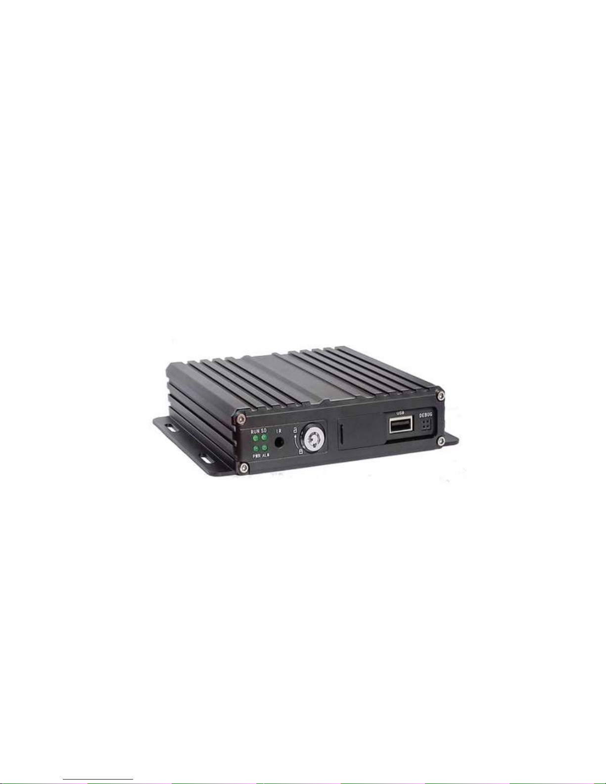
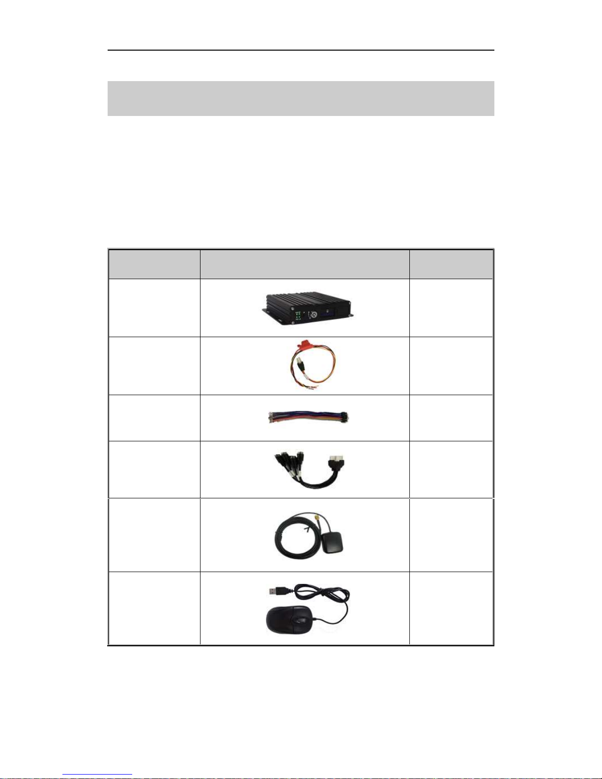
1.DVR and accessories.....................................................................................................1
2.System connection.........................................................................................................2
3.Panel introduction...........................................................................................................3
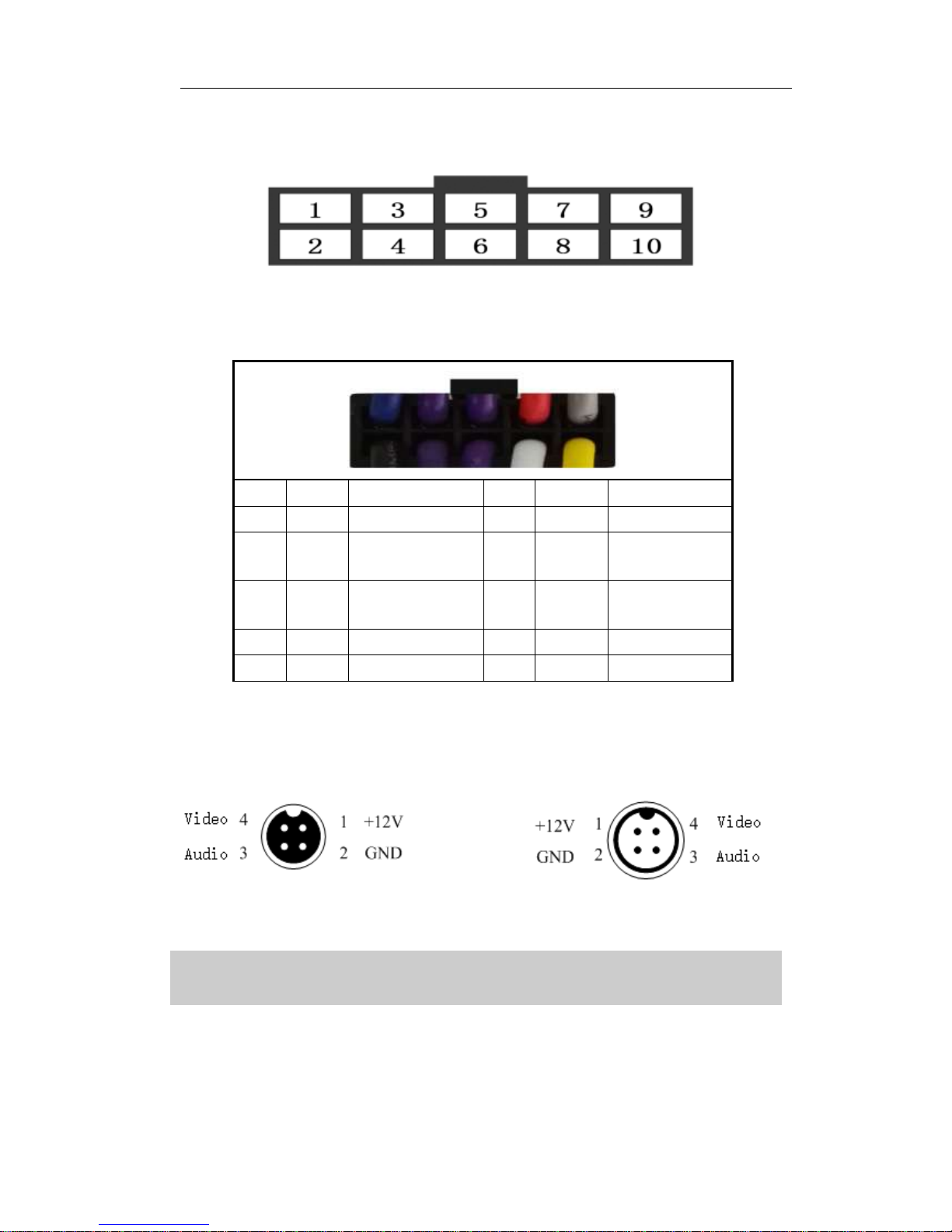
4.Interfaces Definition.......................................................................................................3
4.1 Power interface ...............................................................................................................3
4.2 I/O Interface definition...................................................................................................4
4.3 Aviation interface definition.........................................................................................4
Chapter 2 Installation and Application ...................................................................................4
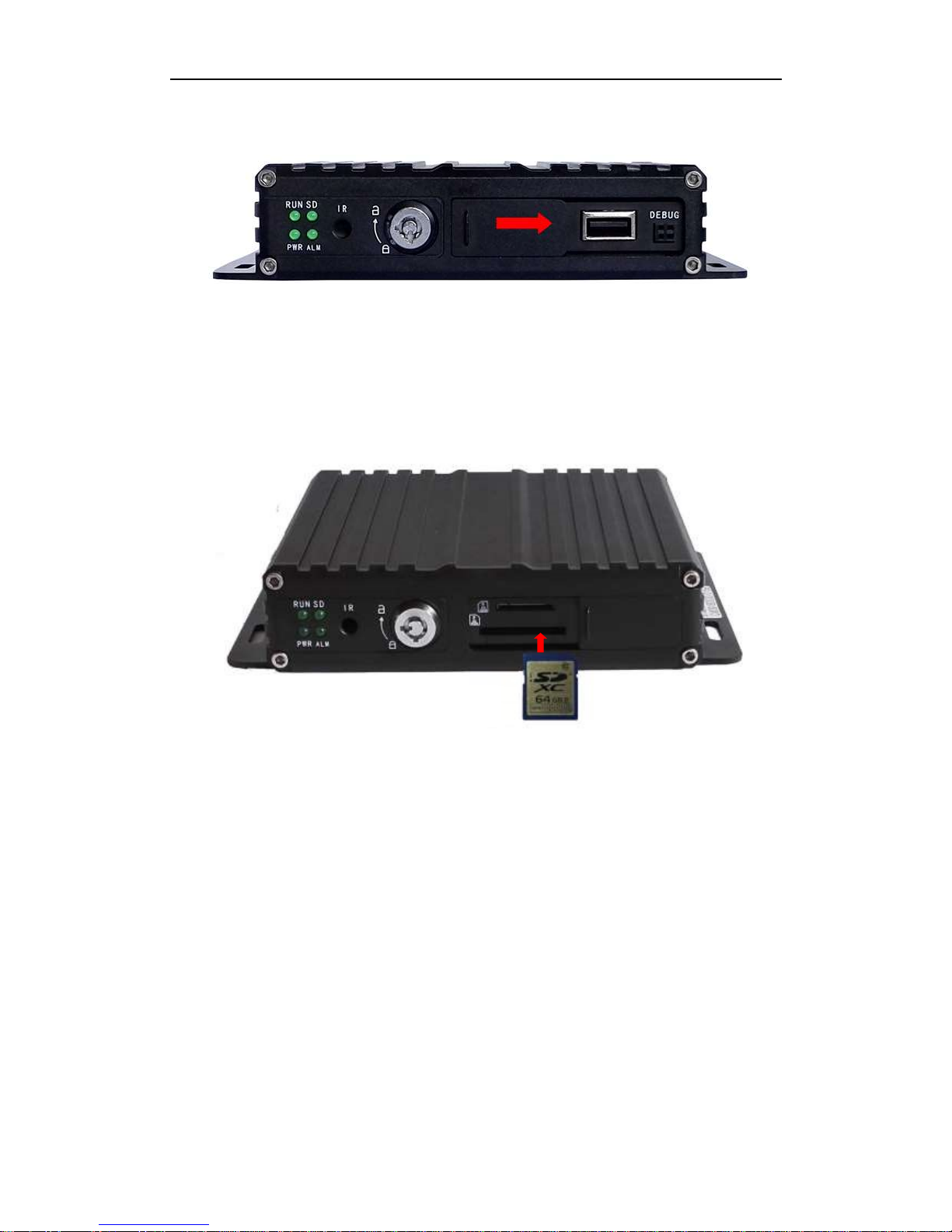
1.SD card installation ........................................................................................................4
2.Antennas Connection ....................................................................................................5
3.Power Connection...........................................................................................................6
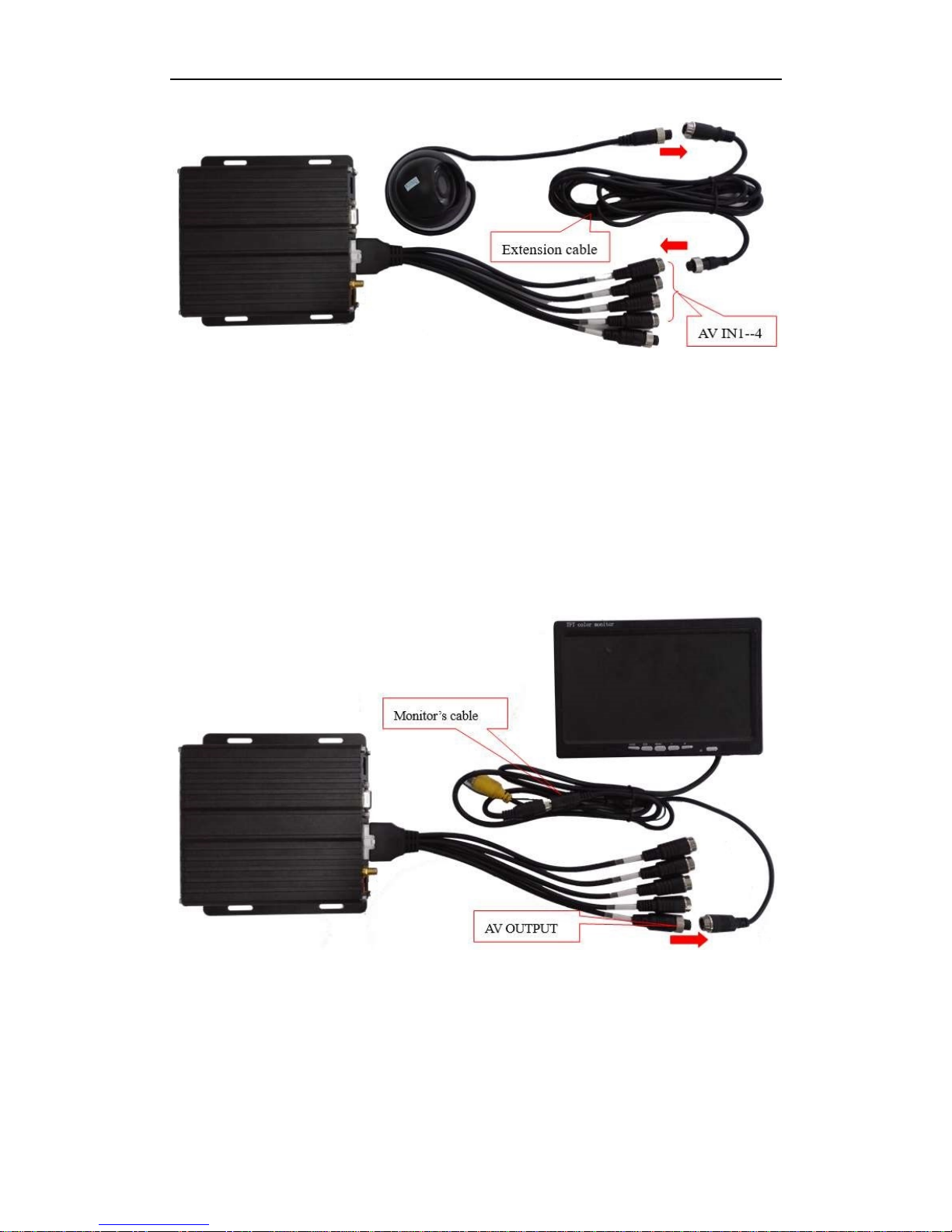
4. Camera Connection..........................................................................................................6
5.Monitor connection.........................................................................................................7
6.I/O wires connection.......................................................................................................8
6. Alarm input connection ..................................................................................................8
6.1Reverse assistant ..........................................................................................................9
6.2Serial ports connection...............................................................................................11

1
Chapter 1 Accessories and Interface
1. DVR and accessories
Before you use this product please check the accessories in the packing box.
If there is anything missing or damaged please contact your seller. The DVR
and accessories are listed as following:
List of DVR and accessories
Description
Picture
Quantity
DVR
1
Power cable
1
I/O cable
1
AV cable
1
GPS antenna
(TE-CDVR-G
Only)
1
1
USB Mouse
Not included

2
2.System connection
System connection

3
3.Panel introduction
Figure 1. Front panel
Figure 2. Back panel
4.Interfaces Definition
Here we introduce the definition of the interfaces of Power, I/O, AV Input & Output.
See as following:
4.1 Power interface
Figure 3. Power interface definition

4
4.2 I/O Interface definition
Figure 4. Front view of I/O Interface
I/O Interface definition
4.3 Aviation interface definition
AV-IN Camera Interface AV-OUT Monitor Interface
Chapter 2 Installation and Application
1.SD card installation
Please insert the key into the hole of the lock on the front panel, and switch it to the
PIN
Color
Definition
PIN
Color
Definition
1
Blue
Alarm output
2
Black
Ground
3
Purple
Alarm input
2( Positive)
4
Purple
Alarm input 1
5
Purple
Alarm input
4( Positive)
6
Purple
Alarm input 3
7
Red
5V Output
8
White
TXD(TTL Level)
9
Grey
Not used
10
Yellow
RXD(TTL Level)

5
open status, then pull the cover toward right, you will see the SD card slot.
Figure 5. SD card Installation
Please insert the SD card as per the icon indication, Then close the SD cover and lock
it (Please remember to lock it, otherwise, The SD card will not work)
Figure 6. SD card installation
2.Antenna Connection (TE-CDVR-G only)
Please connect the GPS antenna as per the picture as below. We suggest you put the
GPS antenna externally on the vehicle’s roof for maximum reception.

6
Figure 7. Antennas Connection
3.Power Connection
Connect power and ground to the vehicles circuits with RED to constant power (10-36V
DC), YELLOW to ignition (5-36V DC) and black to chassis ground.
Figure 8. Power Connection
The yellow ignition wire is used to detect the ignition signal. We strongly suggest
you connect it with the “RUN” terminal of the ignition switch, or any terminal in the
vehicle’sswitch box which will have power only when the vehicle is turned on.
4. Camera Connection
You can connect the camera with the AV input cable directly, or by extension cable
(optional). The AV cable in the accessories box has mark on each connector, AV 1-4
are for cameras connection.
g
g
p
s

7
Figure 9. Cameras connection
Note: Before you connecting the cameras, please double check the resolution of
the AV interface, make sure your cameras are the same resolution as set in the DVR.
5.Monitor connection
The device supports VGA and CVBS output. You can switch the output mode in the
menu.
Figure 10. Monitor connection
Note: Before you connecting the monitor, please double check the resolution of
the AV interface, make sure your monitor is the same resolution as the DVR output.

8
6.I/O wires connection
When you're going to use it, please connect the wires as the I/O interface definition. You
will also find tips of the interface definition in the DVR menu.
Alarm input connection
This device provides 4 channels alarm inputs (2 channels Positive trigger, 2 channels
negative trigger). You can connect the positive pole of circuit of the reverse light, turn
light, door open & close etc with them for applications such as reverse
assistant, camera channels switching.
Figure 12. Alarm Input Connection
I/O wires Alarm Trigger
PIN Definition Color Color Alarm trigger
3 Alarm input2 Purple Red 5-32V
5 Alarm input4 Purple
4 Alarm input1 Purple Black Ground
6 Alarm input3 Purple
Alarm input Connection

9
6.1 Reverse assistant
The device comes with a Reverse assistant feature.
Example of setup: with Alarm Input2 connected to the positive pole of reverse
light’s power, see as following:
Figure 13. Reverse Assistance Connection
I/O wires Alarm trigger
PIN Definition Color Color Alarm Trigger
3 Alarm input 2 Purple Red Positive pole of
Reverse light
Reverse Assistance Connection

10
“RearCamera”, see as following, click “OK” Setup in the DVR menu “Advanced”
AV: Please select the reverse camera’s channel
InputSwitch: Please select the alarm input number which is connect with the
reverse light’s power
Note: When using reverse assistance, please use IN2 or IN4 positive trigger
When you shift to reverse, the DVR will display the reverse camera’s channel only.
See as following:
Figure 14. Reverse Assistance
Click”Zone”
Adjust the lines by
dragging the blue points

11
6.2 Serial ports connection
The device provides a group of serial ports which are used to connect with some
user’s peripherals, the interface is LVTTL (3.3V) level
Figure 17. Serial ports Connection
I/O wires Peripherals
PIN Definition Color Color Definition
2 Ground Black Black Ground
8 TXD(TTL
level) White Yellow RXD
10 RXD(TTL
level) Yellow White TXD
Serial ports connection

Software Guide

~ I ~
Catalogue
Chapter 1 Overview ..................................................................................................................1
Chapter 2 Quick setup .............................................................................................................1
1.Device Installation...........................................................................................................1
2. User Login ..........................................................................................................................1
3.Set up the System time..................................................................................................2
4.Set up cameras................................................................................................................2
5.Wizard ................................................................................................................................3
Chapter 3 System Menu ..........................................................................................................4
1.1 Video Playback.........................................................................................................4
1.2 Video Backup............................................................................................................4
2.Basic Setting....................................................................................................................5
2.1 Date Time setting.....................................................................................................5
2.2 Vehicle Information..................................................................................................6
2.3 Preview setting.........................................................................................................6
2.3 Video Output .............................................................................................................7
2.4 On/Off setting............................................................................................................7
2.5 System Information.................................................................................................7
3.Network setup.................................................................................................................9
4.Recording Setup.............................................................................................................9
4.1 Recording Mode setting........................................................................................9
4.2 Main Stream.............................................................................................................10
4.3 Sub Stream..............................................................................................................10
4.4 Recording storage.................................................................................................11
4.5 Recording OSD (On Screen Display)................................................................11
4.6 Image setting...........................................................................................................12
4.7 Mirror setting...........................................................................................................12
5.Advanced setting..........................................................................................................12
5.1 User Management..................................................................................................13
5.2 Driving Habits monitoring ...................................................................................13
5.3 UART setting...........................................................................................................13
5.3.1 UART-TTS.............................................................................................................14
5.3.2 UART-Serial Net (Pass Through)....................................................................14
5.4 Reverse Camera.....................................................................................................14
5.5 NetTextShow...........................................................................................................15
2.6 System Setup . ...........................................................................................................8
2.7 System Information .................................................................................................8

~ II ~
6.Device Maintenance .....................................................................................................16
6.1 Log Inquiry...............................................................................................................16
6.2 Disk Management..................................................................................................17
6.3 Related with the Parameter.................................................................................17
6.4 System upgrading .................................................................................................17
7.Alarm setting..................................................................................................................18
7.1 Input Alarm..............................................................................................................18
7.2 AlarmOut setting....................................................................................................19
7.3 Video Loss...............................................................................................................20
7.4 Fatigue Driving Alarm...........................................................................................20
7.5 OverSpeedAlarm....................................................................................................21
7.6 DiskError..................................................................................................................21
Chapter 4 Installation Warnings..........................................................................................22

~ 1 ~
Chapter 1 Overview
TE-CDVR is a DVR designed for Analog HD vehicle monitoring. With built-in high
performance image processor and advanced H.264 video compression technology, it
provides AHD video recording, storage and playback solution. It comes with smart
power management system which can recognize the power type automatically. When
detected the battery’s voltage is lower than the given value, the device will shutdown
automatically and keep ultra-low standby consumption.
Chapter 2 Quick setup
1.Device Installation
Please refer to Hardware Guide for installation and cables connection.
2. User Login
Right click the mouse, you will call out the login interface, please input your UserName,
Password, and select your language, click “OK” to login the menu. (The default
UserName is admin, without Password), see below:
User Login Interface

Figure 1. System Menu
“Menu” is the primary screen of the system setup and control, see below:
Figure 2. Primary Menu
3.Set up the System time
Path: Basic->DateTime, see below:
Figure 3. System date and time
TimeSYNC: Date and Time can be synchronized with GPS/BD
4.Set up cameras
Path: Menu->Record->Mode. Please set up your cameras’ SignalType and Valid/Invalid.
The DVR works with both AHD and general cameras. If you use AHD cameras, please
select the first Type, if you use general cameras, please select the third Type, if you use
both
~ 2 ~
Right click the mouse, select “Menu” to start setup menu, see below:

general and AHD cameras, please select the second Type. See as following:
Figure 4. Recording setting
Figure 5. SignalType setup
Note: If your cameras don’t display image on the monitor, please check this setup.
5.Wizard
Path: Menu->Wizard. This Wizard is not applicable to the TE-CDVR-4 or TE-CDVR-G
~ 3 ~
This manual suits for next models
1
Table of contents
Other iBeam DVR manuals