IBM ELECTRONIC MULTIPLIER User manual

I
BM
ELECTRIC PUNCHED CARD
ACCOUNTING MACHINES
CUSTOMER ENGINEERING MANUAL OF INSTRUCTION
ELECTRONIC MULTIPLIER
TYPE
603
INTERNATIONAL BUSINESS MACHINES CORPORATION
NEW
YORK.
NEW
YORK

Published by
Department of Education
International Business Machines Corporation
Endicott, N. Y.
Copyright
1948
International Business Machines Corporation
590
Madison Avenue, New York
22,
N.
Y.
Printed in
U.
S.
A.
Form 22-3838-0

CONTENTS
INTRODUCTION
OPERATING FEATURES
................................................
Main Line Switch
......................................................
Power Indicating Light (Green)
......................................
Start Key
........................................................................
Stop Key
..........................................................................
Error Indicating Light (Red)
.....................................
................................................
Error Reset Push Button
.................................................
Factor Reversal Switch
Card Hopper
................................................................
Card Stacker
...................................................................
Speed
.............................................................................
............................................................................
Current
..............................................................
Control Panel
FUNCTIONAL PRINCIPLES
Multiplication
.....................................................................
Decimals
..............................................................................
One-Half Correction
...........................................................
Double Punch and Blank Column Detection
................
Multiplication Check
.......................................................
Group Multiplication
..........................................................
Product Overflow
................................................................
Product Summary
...............................................................
Column Splits
......................................................................
Punch Suppression
..............................................................
Class Selectors (Optional)
................................................
Distributor (Optional)
......................................................
Sign Control (Optional)
...............................................
Sign Corltrol Checking
.....................................................
MECHANICAL PRINCIPLES
Location of Parts
........................................................
Drive Mechanism
............................................................
Punch Clutch
..............................................................
Feeding Mechanisms
....................................................
Index and Cycles
...............................................................
Geneva Mechanism
..................................................
Single Revolution Timing Cam
..................................
Principle of Punching
................................................
Magnet Unit
.....................................................................
.........................................................................
Oil Pump
Cam Contacts
....................................................................
ADJUSTMENTS
PUNCH CLUTCH
......................................................................
GENEVA MECHANISM
..........................................................
Single Revolution Timing Cam
..........................................
Single Revolution Timing Cam Bracket
.........................
Geneva Clutch
.................................................................
PUNCH UNIT
.............................................................................
Belt Tension
.......................................................................
Feed Roll Tension
................................................................
..........................................................
Feed Knife Guides
Feed Knife Projection
..................................................
...............................................................
Feed Knife Block
........................................................
Hopper Guide Posts
...........................................................................
Throat
......................................................................................
Die
............................................................
Punch Bail Tongue
Interposer Pawl Lock Bar and Spring Bail
....................
Punch Magnet Armatures
................................................
......................................
Punch Bail Connecting Links
Punch Hopper Side Plates
.............................................
Punch Brush Lateral Alignment
..................................
Anchor Slide Adjustment
..............................................
Brush Timing
................................................................
Vertical Registration
.......................................
.....................................................................
Stacker Plate
..........................................................
Stacker Timing
.....................................................................
CONTACTS
Adjustment of Cam Contacts
........................................
...........
Adiustinent of Card Lever Contacts
ELECTRICAL PRINCIPLES
PUNCH UNIT CIRCUITS
........................................................
............................................................
Time Delay Circuits
........................................
Start Circuit and Bias Interlock
Start Interlock Circuits (Gang Punching Only;
............
Start and Running Circuits (No Cards in Machine)
-~----
Start and Running Circuits (Cards in Machine)
...........
......................................................
Reading Brush Circuits
I,
lectronic Computing Control Circuits
..........................
..............................................................
Punch Suppression
...............................................................
Product Summary
...............................................................
Product Overflow
Factor Reversal and Check Circuits
..................................
..............................................................
Group Multiplying
Column Split,
0
and
X,
Hot
1
.....................................
Sign Control (Optional Feature)
.....................................
Class Selectors (Optional)
.................................................
Distributor (Optional)
.....................................................
POWER SUPPLY CIRCUITS
....................................................
Main Transformer and Selenium Rectifiers
........................
Tube Power Supply Chassis
...........................................
Constant Ratio Voltage Regulator
...................................
Screen Grid Supply
.............................................................
Voltage Adjustments
......................................................
PRINCIPLE OF MULTIPLYING
Computing
Circuits-General
BASIC CIRCUITS
TRIGGER CIRCUIT
.......................................................
77
Theory of Operation
....................................................
77
Coupling of Trigger Circuits
........................................
85
Trigger Circuits Used in Electronic Computing
..
86
Control of Other Tubes by Triggers
................................
89
ELECTRONIC COUNTER
........................................................
91
Indicator Blocks
..................................................................
97
Counter Read-In from Card
...........................................
98
Read-In Pulse Circuit
........................................................
100
Counter Read-In at High Speed
..................................
101
COMPUTING CIRCUITS
....................................................
103
Multivibrator and Clippers
........................................
103
Electronic Timers
...................................................
110
Compute Start Control and Primary Timer
...................
112
Secondary and Tertiary Timers
....................................
113
Multiplier Advancing Pulses
....................................
114
Ten-Pulse Control
................................................
119
Multiplicand Counter Rolling Control
.........................
121
Multiplicand Read-Out
...............................................
124
Column Shift Switches
............................................
127
Tertiary Timer and Colun~nShift Control
.................
131
Carry Control and Carry Circuits
.............................
134
Half-Entry
..............................................
139
Compute Stop
...................................................
140
Read-Out Circuits
.................................................
142
TESTING PROCEDURE AND TROUBLE ANALYSIS
Use of Neon Indicator Bulb. Voltmeter and Oscilloscope
149
PURPOSE OF TUBES IN THE COMPUTING SECTION

Feed Hoppar Start-Stop Keys
\
Joggle Plate
/
/
Read
and
Punch
Unit
Electronic Computing
Unit
ELECTRONIC MULTIPLIER
Type
603

IBM ELECTRONIC MULTIPLIER
TYPE
603
INTRODUCTION
THE
CONVENTIONAL
mulriplying machine using
mechanical counters for the computation of pro-
ducts is considerably limited in its speed of oper-
arion because of the inertia of moving parts. By
the use of electrical computation circuits, calculat-
ing speeds can be increased considerably. The Elec-
tronic Multiplier makes use of recently-developed
electronic circuits which calculations at
extremely high speeds. Thus the burdensome and
usually slow-speed process of computing products
is reduced to an automatic high-speed process in
keeping with the other high-speed functions of the
IBM Accounting Machine Method. Calculations
involving earnings, material costs, discounts, in-
ventories, and many other computations can be
effected automatically to speed up the accounting
routines which normally require much time and
ond, between the reading and punching of each
card.
OPERATING FEATURES
THE
operating controls and features of this ma-
chine, which can be seen in Figure
1,
are all located
on the punch unit.
Main Line Switch
This switch must be
ON
for the machine to be
operative. It must not be turned
OFF
while cards
are feeding through the machine.
Power Indicating Light (Green)
When this light is
ON,
the machine is ready for
operation. It will not turn on until suficient time
has been allowed for the electronic tubes to warm
effort. UP.
The Type 603 Electronic Multiplier consists es-
Start Key
sentially of a unit for reading and punching and
an electronic computing unit connected by a cable This key is depressed to start the feeding of
as shown by the general view of the machine on the cards at the beginning of a run. It must be held
frontispiece. The factors punched in an IBM Card down through three machine cycles, when first
are read by the reading unit, computations are starting, before automaric operation begins.
automatically made by the electronic computing
unit, and +theresult is then punched in the same
card by the punching unit. No time is lost wait-
ing for the completion of the computing oper-
ations; all computations are performed between
the time a card leaves the reading brushes and the
time it reaches the punching position. The mach-
ine is equipped with a control panel which makes
it entirely flexible as to the reading and punching
of information.
The IBM Electronic Multiplier, Type 603, repre-
sents the first commercial use of electronics for
multiplication. The use of electronic circuits for
computing permits operation of this multiplier at
maximusr punching speed of 6000 cards per hour.
The multiplication itself is performed in .027 sec-
Stop Key
This key is depressed for manual control of stop-
ping the feeding of cards while the machine is
through running.
Error Indicating Light (Red)
This light glows when an error is detected by the
Double Punch and Blank Column Detection De-
vice, or when a product exceeds the card field
capacity as indicated by the Product Overflow
feature.
Error Reset Push Button
This button is depressed to extinguish the error
light and restore the machine to normal operation,
after the machine has stopped because of an error.

2
TYPB,
603
'E.LECTR.ON.lt'MULTlPLF,ER
;
Card
Face
Edge
Figure
I.
Operating Features
Indicating
(Red)
#
Factor Reversal Switch Speed
When set
ON,
this switch autamatically reverses The operating speed of rhis machine is
100
cards
the multiplier and multiplicand entry hubs. It is per minute regardless of the number of columns
used in checking operations. punched and the size of the multiplier or multi-
Card Hopper
plicand fields.
Cards are placed in the card hopper face down,
current
9
edge first. The capacity of the hopper is approxi- This machine is supplied to operate only on
11
5
mately
800
cards. volts or
230
volts
A.C.,
SO
or
60
cycle current.
Card Stacker Control Panel
After leaving the last set of brushes, cards enter
the stacker which has a capacity of approximately The automatic control panel provides a means
1000
cards. If the stacker fills
to
capacity, the for flexible setup of rhe machine for all operations.
machine will be stopped automatically by the Figure 2 shows
a
control panel with the function
stacker stop switch. of each hub described.
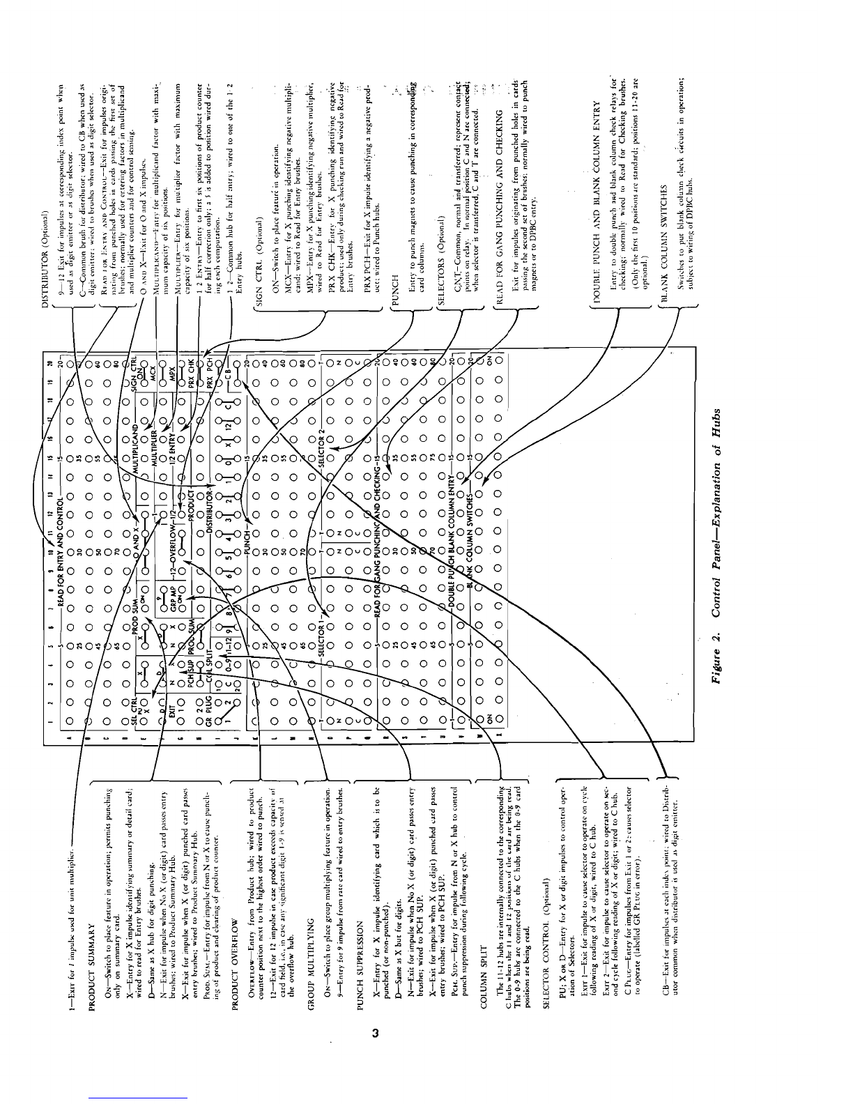
Figure
2.
Control Panel-Explanation of Hubs

FUNCTIONAL PRINCIPLES
Multiplication
The Electronic Multiplier can multiply two
6-
digit factors to produce a 12-digit product. Fig-
ure
3
shows control panel wiring for an individual
mulriplication problem. The multiplier and mul-
tiplicand are read from the card at the first read-
ing station, represented on the control panel by
the 80 exits labelled "Read for Entry and Con-
trol." They are wired to rhe multiplicand and
multiplier counter entries. The product is avail-
able for punching at Product Exit. The product
exit positions from which the product is read must
be wired
TO
the Punch Entry hubs representing the
columns in which the product is to be punched.
order. These positions are represenred on the con-
trol panel by the hubs labelled "Double Punch and
Blank Columh Entry." These hubs are supple-
mented by 10 control panel switches labelled
"Blank Column Switches" which correspond to the
10 DPBC entry hubs. The blank column switches
must be set
ON
for blank column checking.
Multiplication Check
In order thar the double punch and blank col-
umn feature may be used for checking multipli-
cation, it should be used on each original multi-
plying run to prove that only one hole has been
punched in each product column and that no coI-
Decimals
umns are unpunched. For this purpose, the product
When either of the two factors contains deci- field columns in Read for Checking should be
mals, the decimal in the product will wired ro Double Punch and
lank
column ~ntr~,
equal the sum of the decimal ~ositionsof .the fac- as shown in Figure
3.
tors. Only those decimal positions which are to When the punching has been checked in the
be retained in the product are wired from Product original run, the double punch and blank column
Exit to Punch Entry. detection feature may then be used in a separate
One-Half Correction
When some decimal places are dropped from a
product, rhe product can be corrected to the near-
est whole number or decimal position by adding
5
to the first position following the retained pro-
duct. In the Electronic Multiplier, this
'/2
cor-
rection can be made in any of rhe six right-hand
positions of the product counter. On the control
panel,
52
entries are located directly above the
product exits, and the
'/2
entry common is ad-
jacent. The
5
for
'/2
correction will be entered
inro the product counter during multiplication,
once for each card.
run to prove the calculation. The cards are re-run
through the machine with the wiring of .the mul-
tiplicand and multiplier counters reversed by
plat-
ing the factor reversal switch
ON.
During this
second operation the machine again multiplies and
punches the resulr in the product field. With the
product field wired from Read for Checking to
the DPBC Entry, any product punched in this
re-run which differs from the original product will
cause a double-punched column and will therefore
be sensed by double punch detection. If an error
is detected, the machine will srop and turn on the
red light at the front of the machine. The reset
button must be depressed to turn the lighr out.
Double Punch and Blank Column Detection
The start key must then be depressed for one card
The Electronic Multiplier is equipped with 10 cycle, at the end of which time the card in error
double punch and blank column detection posi- will be in the top position in the stacker and may
tions. Ten additional positions are available on be removed for review.
FUNCTIONAL PRINCIPLES
5
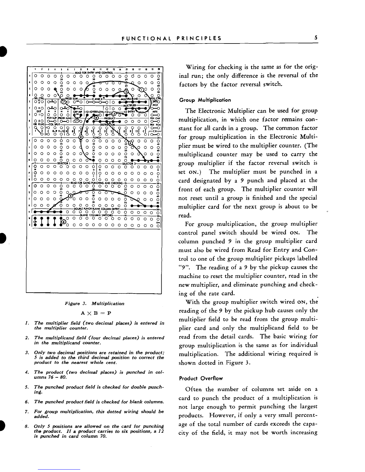
Figure
3.
Multiplication
The multiplier field (two decimal places) is entered in
the multiplier counter.
The multiplicand field (four decimal places) is entered
in the multiplicand counter.
Only two decimal positions are retained in the product;
5 is added to the third decimal position to correct the
product to the nearest whole cent.
The product (two decimal places) is punched in col-
umns
76
-
80.
The punched product field is checked for double punch-
ing.
The punched product field is checked for blank columns.
For group multiplication, this dotted wiring should be
added.
Only
5
positions are allowed on the card for punching
the product. If
a
product carries to six positions,
a 12
is punched in card column
70.
Wiring for checking is the same as for the orig-
inal run; the only difference is the reversal of the
factors by the factor reversal switch.
Group Multiplication
The Electronic Multiplier can be used for group
multiplication, in which one factor remains con-
stant for all cards in a group. The common factor
for group multiplication in the Electronic Multi-
plier must be wired to the multiplier counter. (The
multiplicand counter may be used to carry the
group multiplier if the factor reversal switch is
set
ON.)
The multiplier must be punched in a
card designated by a
9
punch and placed at the
front of each group. The multiplier counter will
not reset until a group is finished and the special
multiplier card for the next group is about to be
read.
For group multiplication, the group multiplier
control panel switch should be wired
ON.
The
column punched
9
in the group multiplier card
must also be wired from Read for Entry and Con-
trol to one of the group multiplier pickups labelled
"9".
The reading of a
9
by the pickup causes the
machine to reset the multiplier counter, read in the
new multiplier, and eliminate punching and check-
ing of the rate card.
With the group multiplier switch wired
ON,
the
reading of the
9
by the pickup hub causes only the
multiplier field to be read from the group multi-
plier card and only the multiplicand field to be
read from the detail cards. The basic wiring for
group multiplication is the same as for individual
multiplication. The additional wiring required is
shown dotted in Figure
3.
Product Overflow
Often the number of columns set aside on a
card to punch the product of a multiplication is
not large enough to permit punching the largest
products. However, if only a very small percent-
age of the total number of cards exceeds the capa-
city of the field, it may not be worth increasing

6
TYPE
603
ELECTRONIC MULTIPLIER
the size of the card field, thereby limiting the
number of columns available for other punching.
To take care of such cases, the product overflow
feature is furnished on this machine.
To place the product overflow feature in
opera-
tion, the product counver position
next
to
the
highest order wired to punch is wired to the Pro-
duct Overflow Entry hub. As long as the product
counter position wired to Product Overflow con-
tains 0, nothing happens. Any digit from 1
through
9
in this position causes the error light to
glow and the machine to stop when the card in
error is just ready to enter the stacker.
Since athe error light is used for other error sig-
nals, it is desirable to distinguish between errors
and overflow products. This is accomplished by
punching
a
12 hole in a card in which the product
exceeds the card field capacity. To punch the 12,
the Product Overflow 12 hub is wired to any
punch magnet, and
a
12 hole will be punched in
the overflow card.
With this arrangement,
a
card is examined after
an error light, and if
a
12 hole is punched, it is
apparent that the error was due to an overflow
product. This card can then be processed man-
ually.
The necessary control panel wiring is shown by
wiring
8
in Figure
3.
A 12 is punched in column
70 of the card with an overflow product (Figure
3).
Product Summary
Often it is desired
TO
accumulate several pro-
ducts before punching. This permits special oper-
ations, such as crossfooting on two cards, punching
the sum of several products, etc. To accomplish
this it is necessary to prevent reading out and clear-
ing of the product counter.
The product summary feature is placed in opera-
tion by wiring the
PROD
SUM
control panel switch
ON.
This feature may be either No
X
or
X
controlled. Digit control is also provided. If
it is desired to punch the product only in
X
Figure
4.
Use of Product Summary and Column Splits
I.
The multiplier field is entered in the multiplier counter.
2.
The multiplicand field is entered in the multiplicand
counter.
3. The product is half corrected by adding
5
to the 3rd
position.
4.
The product is punched in card columns
54
-
60 sub-
ject to the Product Summary Wiring.
5.
The Product Summary feature is placed
in
operation.
6.
X
punchings in the cards to be punched with the
products are sensed.
7.
When an X-punched card passes the die, the product
is punched in the card and the counter is cleared.
8. An X is punched in column 80 and an
0
in
column
I,
in all cards bymeans of the
0
and
X
and Column Split
features.

FUNCTIONAL PRINCIPLES
7
punched cards, the control panel wiring would be
as shown in Figure
4.
The standard wiring of the
multiplicand, multiplier, half-entry, etc. remains
the same as before. Of course, blank column check-
ing cannot be done in this case because many of
the cards are blank. However, double punch
checking may be used if desired.
If ir
is
desired to punch in No X (or digit)
cards, the
N
hub is wired to the
PROD
SUM
hub,
below it. In this case X punched cards will not
be punched, and the product will not clear.
A
blank card with the proper control punching
must precede a product summary run to insure rhe
clearing of the product counter provided a pro-
duct summary run is made immediately after turn-
ing the machine on. This card will insure the clear-
ing of any random figures from the product
counter, resulting from turning the power on. On
normal runs this is not necessary because the pro-
duct counter is cleared before starting the first
computation.
The 1 hub, which emits a 1 impulse during each
card cycle, may be used as a unit multiplier for
special crossfooring operations from card to card
in connection with the product summary feature.
Column Splits
Two positions of column split are available as
standard on this machine. The 0-9 hubs of the
column split are connected wirh the
C
hubs from
9 through
O
of the card, and the 11-12 hubs are
connected with the
C
hubs from 11-12. This de-
vice permits an X or 12 punching over a 0-9 digit
to be recognized independently or to be ignored.
Wiring
8
on Figure
4
shows a typical use of the
column splir device in connection with the
O
and
X
hubs for automatic punching of X's or 0's.
Punch Suppression
If it is desired to suppress punching in a card,
the card is either X punched or punched with a
control digit in a specified column. The control
punching $hen causes the suppression of punching
on that card with proper wiring of rhe control
panel. No X (or digit) control is also furnished,
so that the control punching can appear on the
cards to be punched. This feature permits stan-
dard group (or interspersed) gang punching oper-
a'tions on this machine.
The use of the punch suppression device in con-
nection with two special features, the distributor
and a class selector, is shown in Figure
5.
In this
example, an offset interspersed gang punching op-
eration is being performed.
If
No X (or digit) control is desired, rhe
N
hub
is wired to the
PCH
SUP
hub below. This setup
causes only X (or digit) punched cards to be
punched. Master cards would not be punched
with a control punching.
Class Selectors (Optional)
Class selectors are optional features on rhis ma-
chine. Two class selectors may be installed on
order.
The selectors are arranged for either X or
D
pickup and for normal or delayed operation. If it
is desired to transfer the selector during the cycle
following the reading of the X (or digit), the
GR
PLG
is wired to the Exit 1hub. Wiring the
GR
PLG
to the Exit 2 hub causes the selector to transfer
during the second cycle following the reading of
the X or
D
hole.
Figure
5
shows an example of class selector 1
picking up from a
3
punch in column 80 and
transferring during the second cycle following the
reading of the
3.
Distributor (Optional)
A
conventional 12-segment distributor can be
installed as an optional feature on this machine.
The distributor can be used as a digir emitter by
'
wiring the CB hub to the distributor
C
hub. The
individual hubs of the distributor then emit timed
impulses corresponding to rhe hub label.
The distributor can also be used as a digit selec-
tor by wiring from the brushes to the
C
hub of the

8
TYPE
603
ELECTRONIC MULTIPLIER
Figure 5. Use of Class Selector for OffsetGang Punching
1. A 3 in column 80 is sensed for punch suppression con-
trol and class selector pickup, using a digit selector.
2. Punching is suppressed as the 3-punched card passes
the die and stripper.
3. The class selector
I
transfers while the 3-punched card
passes the second set of brushes.
4.
The No
X
card following the 3-punched card is punched
in card columns 56
-
60 from columns 21 -25.
5. All No
X
cards gang punch in columns 56
-
60.
distributor. Then only the desired digit in any
card column can be recognized by proper wiring
of the
9-12
hubs of the distributor. Figure
5
shows
the distributor used as a digit selector.
Sign Control (Optional)
Sign control permits determination of the sign
(plus or minus) of a product by analysis of the
sign of its factors. Two factors having the same
sign produce a positive product, but if one factor
is positive and the other negative, the product will
be negative.
For multiplication, factors should always be
punched as true figures whether their sign is plus
or minus. In an IBM card the minus sign may be
indicated by an X punch. Any column may be
used forthe X punch, indicating the sign of a fac-
tor, but preferably it should be the unit column of
the factor field.
Wiring for sign control is shown in Figure
6.
To
place the sign control feature in operation, the
SIGN
CTRL
control panel switch must be wired
ON.
There are two sign control pickups on the control
panel, labelled
MCX
(multiplicand X) and
MPX
(multiplier X). One of the two common hubs,
MCX
should be wired from the column in Read for
Entry and Control containing the minus X for
,the multiplicand. One of the two common hubs
MPX
should then be wired similarly for the multi-
plier minus
X.
If only one of the sign control pickups reads an
X, the product should be negative. The machine
will punch the product in true figures, and to
designate the product as negative, will punch an
X in the units column of the product field. To
punch the minus
X
in the units column, the units
position of the product field must be wired from
the
PRX
PCH
hub to the Punch Entry hub (Fig-
ure
6).
The wiring is taken through the column
split to permit
X
punching over the units digit. If
it is desired, the negative product X may be
punched in any column of the card.
Sign Control Checking
When sign control is used in the original calcu-
lation, with a negative product indicated by an X

FUNCTIONAL PRINCIPLES
9
(All X's identifying negative amounts punched over
units position of corresponding field.)
The multiplier factor is entered in the multiplier coun-
ter; the units position is brought through the MPX
hubs to recognize negative multipliers.
The multiplicand factor is entered in the multiplicand
counter; the units position is brought through the MCX
hubs to recognize negative multiplicands.
The product is punched in card columns
74
-
80,
the
units position is taken through the column split to per-
mit both
a
digit and the sign control X to be punched
in the units position.
An
X
identifying
a
negative product is punched in the
units position of the product field through the column
split.
An
X
identifying
a
negative product is read when sign
control checking only.
The product is checked for double punchings and blank
columns; the units position of the product is taken
through the column split hub because of the
X
punched
over the units position in negative products.
Figure
6.
Multiplication
and
Checking with Sign Control
punch, the punching of this minus
X
for the pro-
duct may also be checked during the re-run. In
the re-run, the wiring of the two sign control pick-
ups, as well as wiring of rhe entries to multiplicand
and multiplier counters, is reversed by the factor
reversal switch. To check the minus
X
punch in
the product, the units column of the product field
from Read for Entry and Control is wired to one
of the two common hubs labelled
PRX
CHK
(Fig-
ure
6).
These
PRX
CHK
entry hubs should read an
X
when only one of the two sign control pickups
has read an
X.
If one of these conditions occurs
without the other, an error condition will be indi-
cated.
When checking multiplication with sign con-
trol for double punching, the
X
punched for nega-
tive products must be eliminared from the double
punch check, if it is punched over the product
field. This is done by means of the column split
device as shown in Figure
6.
MEC'H'ANICAL PRINCIPLES
A
STUDY
of the mechanical principles of this ma-
chine is limited to the read and punch uni.t, because
the only mechanical units on the electronic unit
are the blowers. Only the locarion of parts on the
electronic unit will be given in ,this section. The
read and punch unit is essentially the same as a
gang summary punch, and covers are removed in
exactly the same manner.
Location
of
Parts
The five general views of the read and punch
unit in Figures
7
through
11
show the location of
all parts and units which are visible at a glance.
Certain other features not readily visible must be
illustrated schematically.
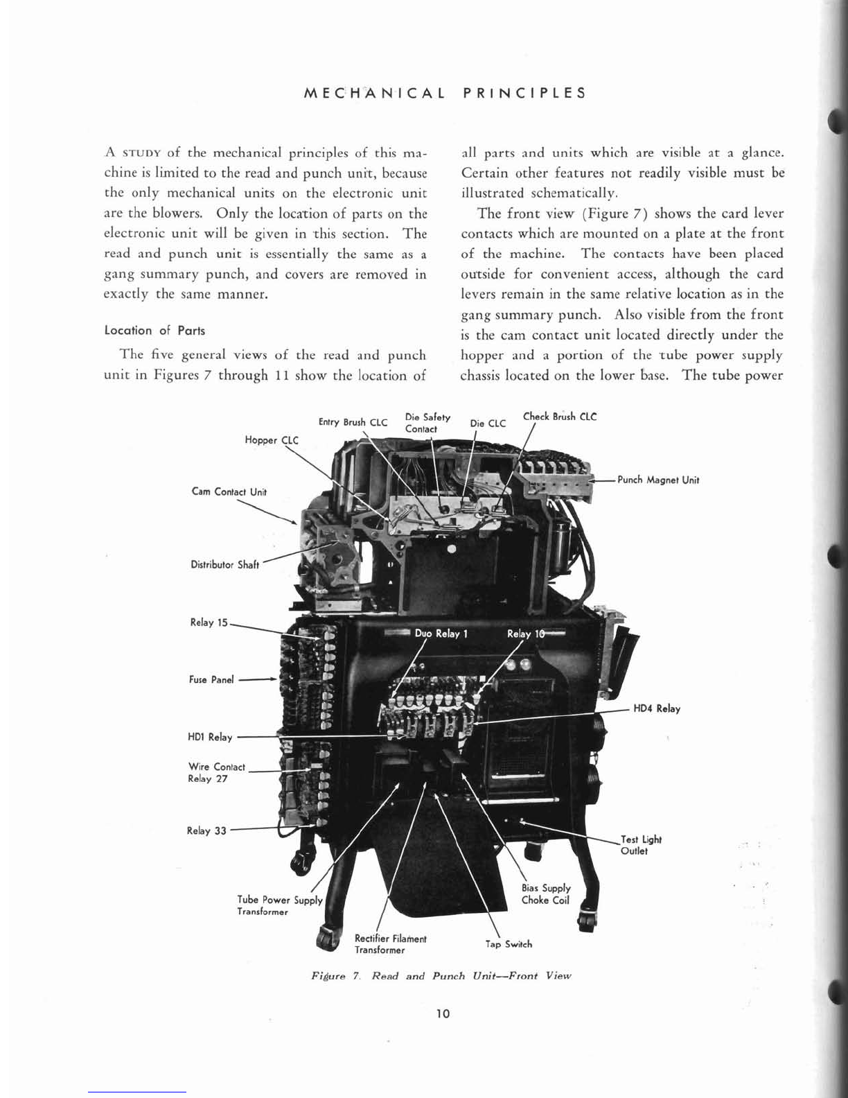
The front view (Figure
7)
shows the card lever
contacts which are mounted on a plate at the front
of the machine. The contacts have been placed
ourside for convenient access, although the card
levers remain in the same relative location as in the
gang summary punch. Also visible from the front
is the cam contact unit located directly under the
hopper and a portion of the rube power supply
chassis located on the lower base. The tube power
Check Brush
CLC
Entry
Brush
CLC
::nE:"
Die
CLC
/
Unit
Relay
Figure
7.
Read and Punch Unit-Front View
10
'
MECH.ANICAL
PRINCIPLES
'
11
Q
Terminal Punch Magnet
80
Terminal Punch Magnet
10
Selt
(Full
Common Terminal
Motor Starting
/
Capacitor
Connector Latch
miurn Rectifier
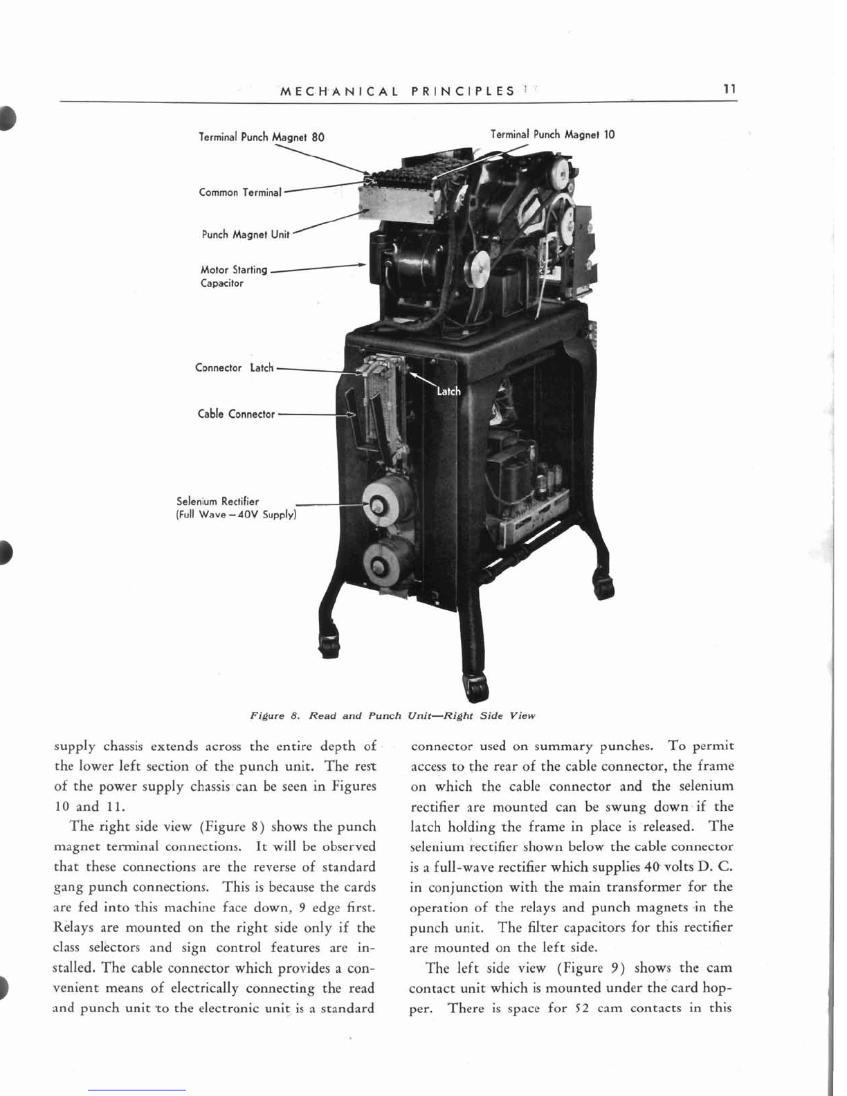
Figure
8.
Read and Punch Unit-Right Side View
supply chassis extends across the entire depth of
the lower left section of the punch unit. The rest
of the power supply chassis-can be seen in Figures
10
and
11.
The right side view (Figure
8)
shows the punch
magnet terminal connections. It will be observed
that these connections are the reverse of standard
gang punch connections. This is because the cards
are fed into rhis machine face down,
9
edge first.
connector used on summary punches. To permit
access to the rear of the cable connector, the frame
on which the cable connector and the selenium
rectifier are mounted can be swung down.if the
latch holding %heframe in place is 'released. The
selenium rectifier shown below the cable connector
is a full-wave rectifier which supplies
40
volts'
D.
C.
in conjunction with the main transformer for the
operation of the relays and punch magnets .in the
Relays are mounted on the right side only if the punch unit. The filrer capacitors for this rectifier
class selectors and sign control features are in- are mounted on the left side.
stalled. The cable connector which provides a con- The left side view (Figure
9)
shows the cam
venient means of electrically connecting the read contact unit which is mounted under the card hop-
and punch unit ro the electronic unit is a standard per. There is space for
52
cam contacts in this

12
TYPE
603
ELECTRONIC MULTIPLIER
,Eccentric
Shah
P1
Cam Contact
P27
Cam Contact
200
mld
Capachrs
I140V
Supply)
Figure
9.
Reed and Punch Unit-Left Side View
I
unit, numbered from front
to
rear, top to bottom. bleeder resistor shown below the rectifier, supplies
I
However, no cams beyond P41 are used, and al-
though cams
9,
13, and 15 are not used, they retain
their numbers. The 12 amp fuses and 20 amp
fusetrons shown at the top of the fuse panel are in
the main transformer circuit. The glass fuses are
in the punch circuits and in the tube power supply
circuits. The conventional arc-suppressing capaci-
tors are mounted between the relay brackets and
above the half-wave selenium rectifier. This selen-
ium rectifier, together with its filter capacitors and
140 volts
D.
C.
for the read-out power tubes in
the electronic unit. The four 2000 mfd. capacitors
shown below the 140 volt
D.
C.
selenium rectifier
are the filter capacitors for the 40 volt
D.
C.
sup-
ply. Thedouble punch and blank column detection
relays
37
through 57 are mounted on the left rear
gate. If 10 additional positions of DPBC detection
are installed, relays
58
through 77 are mounted
just to the left of R37-R57.
a

MECHANICAL PRINCIPLES
13
Oil
Level
Crank
Stud Indicator
Gear Housing
\
Oil
Cup
Figure 10. Read and Punch Unit-Rear View
The rear view in Figure 10 shows the mechan-
ical features visible from the rear as well as the
main transformer and the tube power supply chas-
sis. The tube power supply furnishes
D.
C.
volt-
ages of
100
volts, 150 volrs, and 250 volts for the
operation of tubes in the electronic unit. The main
+
transformer supplies
A.
C.
of proper voltage to the
40 volt and 140 volt selenium rectifiers; it also
supplies -the filaments of all tubes except the gas-
filled rectifier tubes.
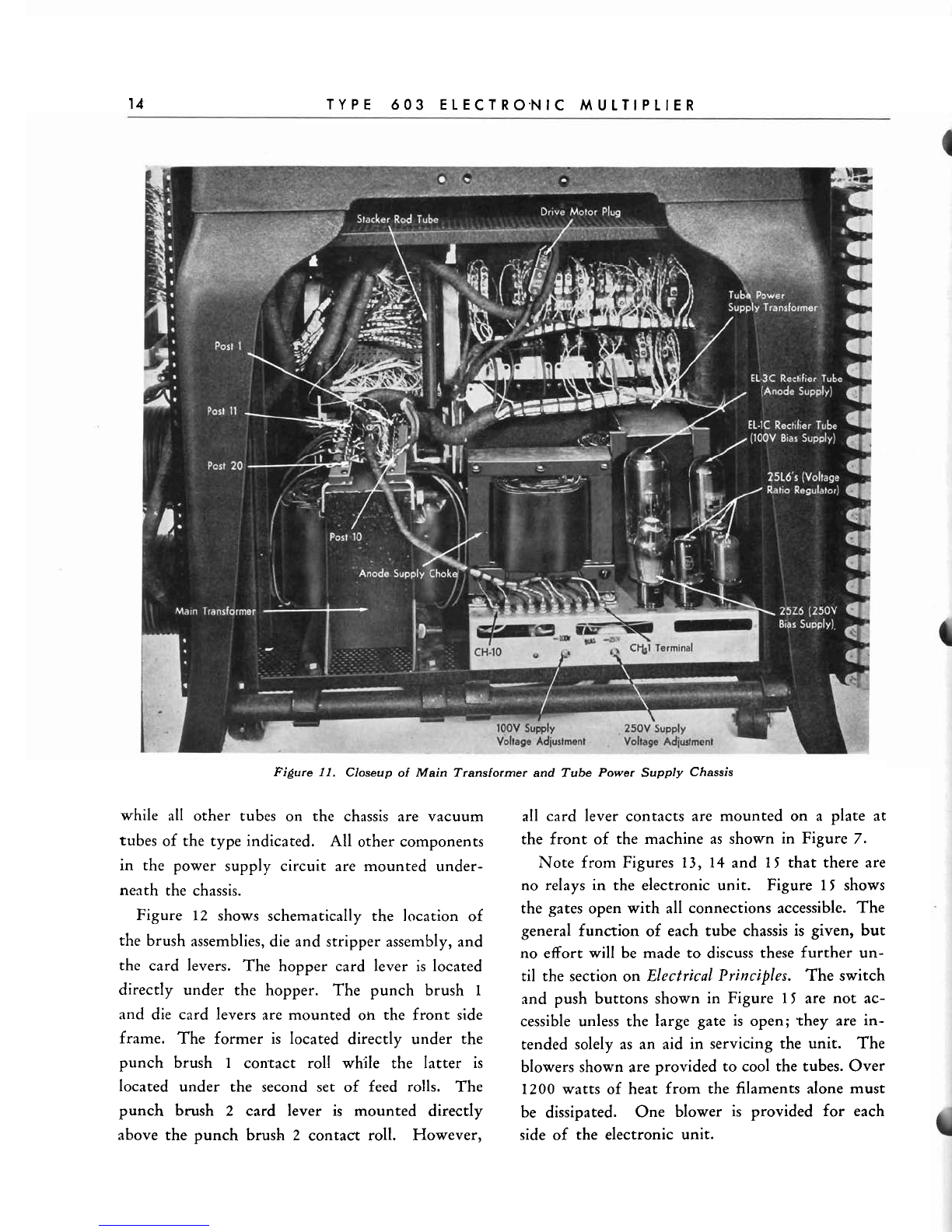
In the close-up view of Figure
11,
a better pic-
ture of -the main transformer and tube power sup-
ply chassis is shown. Note particularly the system
for numbering terminals on both the transformer
and the power supply chassis. The
EL-3C
and
EL-1C
tubes are gas-filled full-wave rectifier tubes,
14
TYPE
603
ELECTR0,NIC
MULTIPLIER
Figure
11.
Closeup
of
Main Transformerand Tube Power Supply Chassis
while
all
other tubes on the chassis are vacuum
tubes of the type indicated. All other components
in the power supply circuit are mounted under-
neath the chassis.
Figure
12
shows schematically the location of
the brush assemblies, die and stripper assembly, and
the card levers. The hopper card lever is located
directly under the hopper. The punch brush
1
and die card levers are mounted
oh
the front side
frame. The former is located directly under the
punch brush
I
con,tact roll while the latter is
located under the second set of feed rolls. The
punch brush 2 card lever is mounted directly
above the punch brush
2
contact roll. However,
all
card lever contacts are mounted on a plate at
the front of the machine as shown in Figure
7.
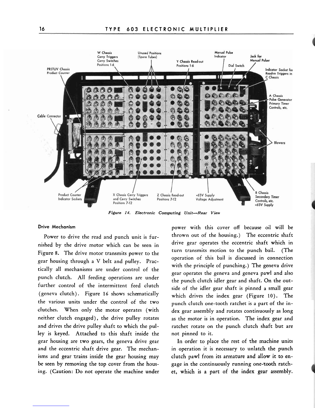
Note from Figures 13, 14 and
15
that there are
no relays in the electronic unit. Figure
15
shows
the gates open with all connections accessible. The
general function of each tube chassis is given, but
no effort will be made to discuss these further un-
til the section on
Electrical Principles.
The switch
and push buttons shown in Figure
15
are not ac-
cessible unless the large gate is open; rhey are in-
tended solely as an aid in servicing the unit. The
blowers shown are provided to cool the tubes. Over
1200
watts of heat from the filaments alone must
be dissipated. One blower is provided for each
side of the electronic unit.

MECHANICAL PRINCIPLES
15
Hopper
i
Reading Station
I
Punching Station
I
I
(Entry and Control)
I
I
Reading Station
(Checkingand
I
Gang Punching)
I
Figure 12. Schematic of Read and Punch Unit
Stacker
H
Chassis
M
Chassis
N
Chassis
Product Input lnverlers
Figure
13.
Electronic Computing Unit-Front View
16
TYPE
603
ELECTRONIC MULTIPLIER
Figure
14.
Electronic Computing Unit-Rear
View
Drive
Mechanism
Power to drive the read and punch unit is fur-
nished by the drive motor which can be seen in
Figure
8.
The drive motor transmits power to the
gear housing through a
V
belt and pulley. Prac-
tically all mechanisms are under control of the
punch clutch. All feeding operations are under
further control of the intermittent feed clutch
(geneva clutch). Figure
16
shows schmatically
the various units under the control of the two
clutches. When only the motor operates (with
neither clutch engaged), the drive pulley rotates
and drives the drive pulley shaft to which the pul-
power with this cover off because oil will be
thrown out of the housing.) The eccentric shaft
drive gear operates the eccentric shaft which in
turn transmits motion to the punch bail. (The
operation of this bail is discussed in connection
with the principle of punching.) The geneva drive
gear operates the geneva and geneva pawl and also
the punch clutch idler gear and shaft. On the out-
side of the idler gear shaft is pinned a small gear
which drives the index gear (Figure
10).
The
punch clutch one-tooth ratchet is a part of the in-
dex gear assembly and rotates continuously as long
as the motor is in operation. The index gear and
ratchet rotate on the ~unchclutch shaft but are
ley is keyed. Attached to this shaft inside the not pinned to it.
gear housing are two gears, the geneva drive gear In order to place the rest of -the machine units
and the eccentric shaft drive gear. The mechan- in operation it is necessary to unlatch the punch
isms and gear trains inside the gear housing may clutch pawl from its armature and allow it to en-
be
seen by removing the top cover from the hous- gage in the continuously running one-~00thratch-
ing. (Caution: Do not operate the machine under et, which is a part of the index gear assembly.
Table of contents
Other IBM Office Equipment manuals

Popular Office Equipment manuals by other brands

Safco
Safco Impromptu 5375 Assembly instructions

Safco
Safco Tuvi 5070 Assembly instructions

hushoffice
hushoffice hushwork.sit&stand HUS-BX-016/116 Maintenance and safety manual

Rexel
Rexel Optima 45 instruction manual

Levira
Levira FALDON Assembly instructions

Wiremold
Wiremold V2400 Series installation instructions


