Evolve EVPCP2 User manual


Evolve Customer Support available at 856/552-4000, 888/827-2500, from 8:30 Eastern through 6 Eastern time, or fax at 856/552-4001.
Page
Panels
Corner Connections – Equal Height (EVPCP2, EVPCP3, EVPCP4) 2
Corner Connections – Variable Height (EVPVP2, EVPVP3, EVPVP4) 3
Corner Connections – Corner Post Extension (EVPCEP2, EVPCEP3, EVPCEP4) 4
Inline Connection – Equal Height (EVPIC) 5
Inline Connection – Variable Height (EVPVC) 6
Notched Top Cap 7
Inline Connection – Panel Extension Module (EVPIEC) 8
End-of-Run Post Kit (EVPER) 9
End-of-Run Post Kit – Wall Mount Application 10
Electrical
Wiring Schematic 11
Power Distribution Housing (EVEPD) 12
Jumper Cables and Pass-Through Cables (EVECJ, EVECP) 13
Directional Floor Power Entry (EVEEFD) 14
Reversible Floor Power Entry (EVEEFR) 15
Ceiling Power Entry (EVEEC) 16
Duplex Receptacle (EVERD) 17
Worksurfaces
End Panel (EVHEP) 19
Corner Bracket (EVHCB) 20
Cantilever (EVHC) 21
Support Leg (EVHS) 22
Storage
Worksurface Supporting Pedestals (EVSBBF, EVSFF) 23
Overhead Flipper Door Storage Unit (EVSOF) 24
Corner Shelf (EVSSC) 25
Low-Profile Shelf (EVSSL) 26
Installation Manual – January 2001 1
Note: Any alterations to listed components will void the manufacturer's warranty. The manufacturer will
not be responsible for any damage or bodily harm caused by alterations in accordance with national or
local electrical codes and manufacturer's specifications.
In accordance with the manufacturer's policy of continual product improvement, the product presented in
this document is subject to change without notice or obligation.
Installation Sequence
Evolve Customer Support available at 856/552-4000, 888/827-2500, from 8:30 Eastern through 6 Eastern time, or fax at 856/552-4001.
Corner Connections – Equal Height
Two-Way (EVPCP2), Three-Way (EVPCP3), and
Four-Way (EVPCP4) Corner Posts
Parts List:
1 Aluminum corner post
1, 2, 3 or 4 slotted posts with levelling glide
(attached to aluminum corner post)
1, 2, 3 or 4 single clamps
Appropriate trim
1 Top cap
Corner Posts are used to connect panels of equal height at a corner.
!
!Always start the installation of panels at a corner.
1. Remove the panel top caps.
2. Partially attach a slotted post to one end of the panel to be
installed. Do this by engaging the down-hook at the bottom of the
panel (above the raceway channel) over the up-hook on the slotted
post.
Attach the opposite end of this panel to one face of the Corner
Post by engaging the down-hook at the bottom of the panel (above the
raceway channel) over the up-hook on the slotted post. (The slotted
post is secured to the face of the Corner Post.)
3. Connect the top of the Corner Post to the panel by engaging the
single clamp through the slotted post and into the panel liner. Secure
the single clamp by bolting it to the top of the panel using two (2) quar-
ter 20 1/2" flat head screws.
4. Repeat the above procedure to attach the second, third and fourth
panel to the Corner Post.
5. Press fit the top cap down onto the top of the Corner Post.
6. Reattach the panel tops caps.
Installation Manual – January 2001
Note: Any alterations to listed components will void the manufacturer's warranty. The manufacturer will
not be responsible for any damage or bodily harm caused by alterations in accordance with national or
local electrical codes and manufacturer's specifications.
In accordance with the manufacturer's policy of continual product improvement, the product presented in
this document is subject to change without notice or obligation.
2
Panels
Panels
Installation Instructions
1
2
3
6
5
4
7
Evolve Customer Support available at 856/552-4000, 888/827-2500, from 8:30 Eastern through 6 Eastern time, or fax at 856/552-4001.
Installation Manual – January 2001 3
Panels
Note: Any alterations to listed components will void the manufacturer's warranty. The manufacturer will
not be responsible for any damage or bodily harm caused by alterations in accordance with national or
local electrical codes and manufacturer's specifications.
In accordance with the manufacturer's policy of continual product improvement, the product presented in
this document is subject to change without notice or obligation.
Panels
Installation Instructions
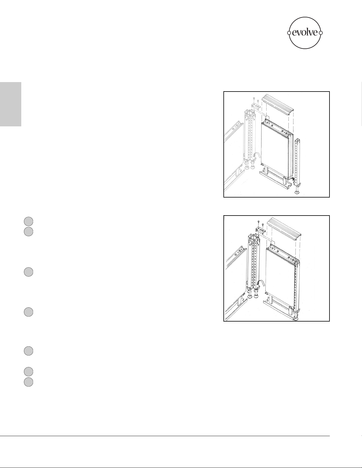
Corner Connections – Variable Height
Two-Way (EVPVP2), Three-Way (EVPVP3), and
Four-Way (EVPVP4) Corner Posts
Parts List:
1 Aluminum corner post
1, 2, 3 or 4 slotted posts of varying heights with levelling glide
(attached to aluminum corner post)
1, 2, 3 or 4 single clamps
Appropriate trim
1 Top cap
Variable-Height Corner Posts are used to connect panels of different heights
at a corner.
!
!Always start the installation of panels at a corner.
1. Remove the panel top caps.
Partially attach a slotted post to one end of the panel to be
installed. Do this by engaging the down-hook at the bottom of the panel
(above the raceway channel) over the up-hook on the slotted post.
2. Attach the opposite end of this panel to the corresponding face of
the Variable-Height Corner Post by engaging the down-hook at the
bottom of the panel (above the raceway channel) over the up-hook on
the slotted post. (The slotted post is secured to the face of the Variable-
Height Corner Post.)
3. Connect the top of the Variable-Height Corner Post to the panel by
engaging the single clamp through the slotted post and into the panel
liner. Secure the single clamp by bolting it to the top of the panel using
two (2) 1/2" flat head screws.
4. Repeat the above procedure to attach the second, third and fourth
panel to the Variable-Height Corner Post.
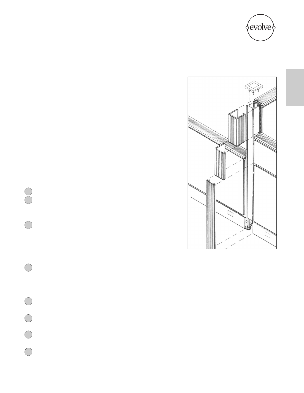
5. Snap the vertical corner trim pieces ("U", "L", and Flat) onto the
corner post. Start at the top and align corner trim with panel top cap.
Press fit the top cap down onto the top of the Variable-Height
Corner Post.
6. Reattach the panel tops caps.
1
2
3
6
5
4
7
8
Installation Manual – January 2001
Note: Any alterations to listed components will void the manufacturer's warranty. The manufacturer will
not be responsible for any damage or bodily harm caused by alterations in accordance with national or
local electrical codes and manufacturer's specifications.
In accordance with the manufacturer's policy of continual product improvement, the product presented in
this document is subject to change without notice or obligation.
4
Panels
Panels
Installation Instructions
Corner Connections – Corner Post Extension
Two-Way (EVPCEP2), Three-Way (EVPCEP3), and Four-Way
(EVPCEP4) Corner Posts
Parts List:
1 Aluminum corner extension post
1, 2, 3 or 4 non-slotted posts (attach to aluminum corner post)
1, 2, 3 or 4 variable-height clamps
Appropriate trim
Corner Post Extensions are used to connect Panel Extension Modules at a
corner. The combination of one 66" panel and three 12" Panel Extension
Modules has been tested and U.L. approved. Special care should be taken
to ensure stability when exceding 90" in height.
1. Remove the post top cap.
2. Remove the panel top caps.
3. Remove the single clamp that attaches the panel to the ocrner
post.
4. Reconnect the top of the panels to the slotted corner posts by
engaging the variable-height clamps through the slotted post. Rotate the
variable-height clamps down onto the top horizontal tubes of the panels.
Secure the variable-height clamps by bolting each to a panel using two
1/2" flat head screws.
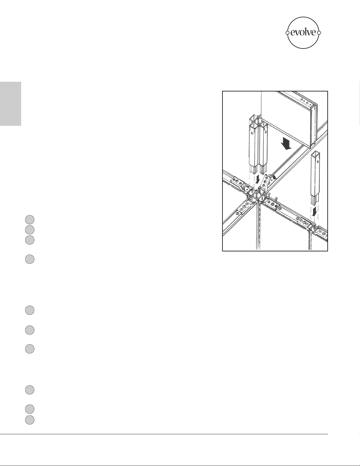
5. Insert the Corner Post Extension into the existing Corner Post,
making sure that it is fully seated.
6. Position the Panel Extension Module on top of the desired,
corresponding panel and against the Corner Post Extension.
7. Connect the top of the Corner Post Extension to the Panel
Extension Module by engaging the single clamp through the slotted
post and into the panel liner. Secure the single clamp by bolting it to the
top of the panel using two 1/2" flat head screws.
8. Repeat the above procedure to attach the second, third and fourth
panel to the Corner Post Extension.
9. Attach the Corner Post top cap.
10. Reattach the panel top caps.
1
2
3
4
5
7
6
9
8
10
Evolve Customer Support available at 856/552-4000, 888/827-2500, from 8:30 Eastern through 6 Eastern time, or fax at 856/552-4001.
This manual suits for next models
28
Table of contents
Other Evolve Office Equipment manuals


Popular Office Equipment manuals by other brands

hushoffice
hushoffice hushtwin HUS-BX-019 Maintenance and safety manual

silen
silen Space 2 Assembly manual

Middle Atlantic Products
Middle Atlantic Products LD Series instruction sheet

SHFL
SHFL DECK MATE BLACKJACK Service manual

VITRA
VITRA Stefan Hürlemann Dancing Wall Assembly instructions

BISLEY
BISLEY Glide V2 Assembly instructions


