IBP Biotech-Lab System User manual

www.ibpmedical.com
Biotech-Lab User Manual
Modular Product Family of Sensors, Simulators and Testers.
HDU-Sensor Family
pH
Temperature
Conductivity
Pressure
Flow

Biotech-Lab User Manual \\ 2www.ibpmedical.com
Foreword
The information contained in this is subject to change without notice. IBP Medical GmbH, its distributors and subsidiaries
take no responsibility for any errors or omissions in this document. The contained software is being delivered on the basis
of a general license contract or in single license. Use or reproduction of the software is allowed only in agreement with the
contractual arrangements. Whoever transfers this software and/or this manual on magnetic tape, diskette or any other media,
except for the purpose of own use, without written authorization of the IBP Medical GmbH, is liable to prosecution.
Author: Werner Pfingstmann
Copyright (C) 2016 IBP Medical GmbH.
All rights reserved
All brand names mentioned in this document are property of their respective owners.
Publisher:
IBP Medical GmbH
Ikarusallee 15 D 30179
Hannover Germany
Internet: http://www.ibpmedical.com
LabCon-L is a subsidiary of IBP Medical GmbH.
REVISIONS
Version Date Author Comments Software Version
1.00 15.05.16 Werner Pfingstmann Initial Version 1.00
1.01 05.09.16 Werner Pfingstmann1.01 Statistic Screen 1.01
added Details optimized

Biotech-Lab User Manual \\ 3www.ibpmedical.com
Table of Contents
1 Introduction .............................................................................................................................................. 5
1.1 Intended use .......................................................................................................................................... 5
1.2 Regulatory ............................................................................................................................................. 6
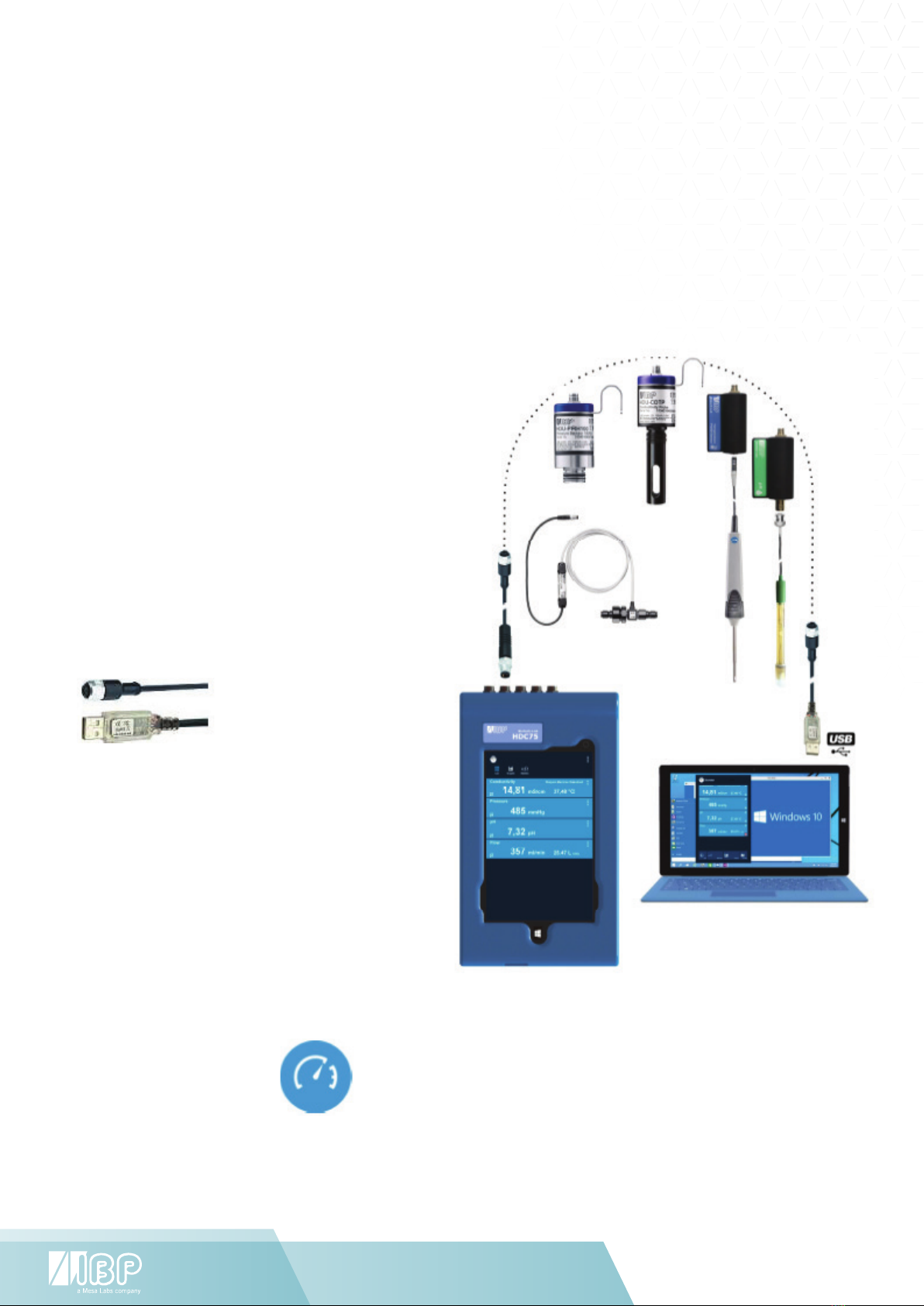
2 Biotech-Lab Overview ............................................................................................................................... 7
2.1 Display and Control Units ...................................................................................................................... 7
3 Biotech-Lab Modules................................................................................................................................. 8
4 Biotech-Lab Software .............................................................................................................................. 10
4.1 Introduction ......................................................................................................................................... 10
4.2 Installation HDC75 .............................................................................................................................. 11
4.3 Installation PC ..................................................................................................................................... 11
4.4 Software Update ................................................................................................................................... 11
5 OS Windows 10 ....................................................................................................................................... 12
5.1 Changing the Display Language in Windows 10 ................................................................................... 12
6 Biotech-Lab Software .............................................................................................................................. 14
6.1 Biometer General Functionality ............................................................................................................ 15
6.2 Head Area Functionality ....................................................................................................................... 15
6.3 Value Display Area Functionality .......................................................................................................... 16
6.4 Single Sensor Graphic .......................................................................................................................... 17
6.5 All Senor Graphics ................................................................................................................................ 17
6.6 Statistic values ................................................................................................................................... 19
7 Sensor Sub Menus .................................................................................................................................. 20
7.1 Conductivity Sensor Details ................................................................................................................. 20
7.2 Temperature Sensor Details ................................................................................................................. 23
7.3 Pressure Sensor Details ....................................................................................................................... 23
7.4 Flow Sensor Details ............................................................................................................................. 24
7.5 pH Sensor Details ................................................................................................................................ 24
8 HDC75 Display and Control Unit ............................................................................................................. 27
8.1 Getting to know the HDC75 .................................................................................................................. 27
8.2 Technical Data .................................................................................................................................... 28
9 HDU-Sensors and Interfaces .................................................................................................................. 29
9.1 HDU-CDTP Conductivity/Temperature sensor ...................................................................................... 29
9.2 HDU-PRH & HDU-PRS Pressure Sensor Family .................................................................................... 30
9.3 HDU-FL Flow Sensors ...........................................................................................................................32
9.4 HDU-Pt100-I Interface for Pt100 temperature sensors ....................................................................... 33
9.5 Pt100 Sensors Temperature Sensor Family: Air - Surface - General Dip - Laboratory ......................... 33
9.6 HDU-pH-I Interface for pH-Sensor ...................................................................................................... 34
9.7 HDU-pHPt-I Interface for pH-Sensor and Pt100 temperature sensors ................................................ 34
9.8 HDU-YSI400-I Interface for YSI 400 temperature sensors .................................................................. 35
9.9 HDU-YSI700-I Interface for YSI 700 temperature sensors .................................................................. 35
10 HSI - Simulators .................................................................................................................................. 35
11 HAT - Tester ......................................................................................................................................... 35
12 Adjustment and Calibration ................................................................................................................ 36
12.1 Adjustment ...................................................................................................................................... 36
12.2 Calibration ....................................................................................................................................... 36
12.3 General ............................................................................................................................................ 36
12.4 Handling of Reference Solutions ...................................................................................................... 37
13 Maintenance of Biotech-Lab modules ................................................................................................. 38
13.1 Storage ............................................................................................................................................ 38
13.2 Cleaning .......................................................................................................................................... 38
13.3 Calibration period ............................................................................................................................ 38
13.4 Accuracy needed for calibration equipment ..................................................................................... 38

Biotech-Lab User Manual \\ 4www.ibpmedical.com
Safety Instructions
Read this First
FOR YOUR SAFETY READ AND CONSIDER THE SAFETY INSTRUCTIONS BELOW CAREFULLY
• Read carefully the entire user manual of the Biotech-Lab system before using the Biotech-Lab system.
• Read carefully the entire manual of the devices under test before connecting the Biotech-Lab system to the devices under
test.
• The battery included with the HDC75 does not arrive fully charged. The battery must be charged for a minimum of 2 hours
prior to use.
• Keep the devices away from unauthorized persons.
• Make sure that all Biotech-Lab Modules have valid calibration certificates.
• Only use the Biotech-Lab system in a dry environment and do not touch it with wet hands.
• Prevent every mechanical overstraining of electrical wires.
• If the acquired values seem to be not believable, make sure that the no device is defective.
• Prevent electrostatic discharge on the connectors. This can lead to substantial damage of the Biotech-Lab devices and
devices under test. Make sure to be completely discharged before touching the connectors or cables connected to the
instrument.
• Potentials above 42 V against earth ground are dangerous. This potentials can lead to electrical shock and therefore to
health hazards. Make sure that none of the connectors has higher voltage than mentioned before.
• Never open a device of the Biotech-Lab system. There are no serviceable parts inside.

Biotech-Lab User Manual \\ 5www.ibpmedical.com
1 Introduction
This documentation describes the installation and use of the Biotech-Lab System. The system includes:
• Display and Control Units
• Sensors
• Interface Modules
• Software
1.1 INTENDED USE
The Biotech-Lab system is intended to be used in biomedical, laboratory and environmental applications.
Do not use any part of the system in life support applications.

Biotech-Lab User Manual \\ 6www.ibpmedical.com
1 Introduction
1.2 REGULATORY
Ec Declaration Of Conformity
We hereby declare, that the following products conform to the below mentioned European Directive.
Manufacturer IBP Medical GmbH
Ikarusallee 15
30179 Hannover
Products HDC75 Display- and Control Unit
HDU-CDTP Conductivity/Temperature Sensor
HDU-PRH High Accuracy Pressure Sensor Family
HDU-PRS Pressure Sensor Family
HDU-FL Flow Sensor Family
HDU-Pt100-I Interface for Pt100 temperature sensors
HDU-pH-I Interface for pH-Sensor
HDU-pHPt-I Interface for pH-Sensor and Pt100 temperature sensors
Relevant EC-Directives 2004/108/EC
2006/95/EC
Compliance With EN 61326
EN 61000-4-2:1996
Place and Date Hannover 15.05.16

Biotech-Lab User Manual \\ 7www.ibpmedical.com
2 Biotech-Lab Overview
2.1 DISPLAY AND CONTROL UNITS
Biotech-Lab System is a modular product family of high precision active sensors, simulators and testers for
biomedical, laboratory and environmental measuring and testing applications. The modular concept of the
Biomed-Lab system allows the use of any combination of sensors in order to fulfil user specific test or
calibration requirements. Only one central unit for all the daily tasks is needed.
The choices:
• HDC75 - a robust smart device
• PC or Tablet with Microsoft Windows
Depending on the requirements you can use
the HDC75 or a standard computer with
Microsoft Windows as display and control
unit for the Biotech-Lab modules.
Biotech-Lab software works with Microsoft
Windows 7 and 10.
Connectivity of Biotech-Lab modules
All Biotech-Lab modules such as sensors,
simulators, analyser and tester feature an
RS485 Interface.
With a special cable the modules can be
connected to a USB computer interface.
HDC75
Account: Biotech-Lab
Password: btl (Biotech-lab)
Support, manual and software updates are available at:
http://www.ibpmt.com/btle.shtm
HDC75
Account: Biotech-Lab
Password: btl (Biotech-lab)
Support, manual and software updates are available at:
http://www.ibpmt.com/btle.shtm

Biotech-Lab User Manual \\ 8www.ibpmedical.com
3 Biotech-Lab Modules
For the Biotech-Lab System a range of interface modules are available. The general groups are:
• HDU - Sensors and Interfaces
• HSI - Simulators
• HAT - Analyser & Tester
Some modules listed below are under development.
If you have special needs please do not hesitate to contact us.
3.1.1 HDU - SENSORS AND INTERFACES
HDU-Sensors are a product family of high precision active sensors for biomedical, laboratory and environmental
applications.
HDU-CDTP Conductivity/Temperature sensor
HDU-PRH High Accuracy Pressure Sensor Family
HDU-PRS Pressure Sensor Family
HDU-FL Flow Sensor Family
HDU-Pt100-I Interface for Pt100 temperature sensors
Available versions depending on the requirements:
Temperature Sensor Family: Air - Surface - General - Dip
HDU-YSI400-I Interface for YSI 400 temperature sensors
HDU-pH-I Interface for pH-Sensor
3.1.2 HSI - SIMULATORS
HDS-Sources and HVS-Simulators are a product family voltage and pressure sources and Vital Signs Simulators for
biomedical, laboratory and environmental applications.
HSI-PSG16 Pressure Sensor and Source -400 to +750 mmHg for:
Static NIBP Monitor test
Static Pressure and Linearity Test
Pressure Leak Test
Over Pressure Test
HSI-ECG Patient Simulator 12 Lead ECG-Signals
HSI-YSI400 Simulator YSI 400 Temperature Sensors
HSI-IBP Simulator Invasive Blood Pressure Sensor
3.1.3 HAT - ANALYSER AND TESTER
HAT- Analyser and Tester include
HAT-ESA Medical Electrical Safety Analyser
HAT-IPA Infusion Pump Analyser

Biotech-Lab User Manual \\ 9www.ibpmedical.com
4 Biotech-Lab Software
4.1 INTRODUCTION
The Biotech-Lab Software is a modular system of different App’s. The structure of the programs is shown below.
The software works with Microsoft Windows 7 and Microsoft Windows 10.
The Biotech-Lab server is the central software module. Additional App’s provide the functionality needed for the
different Biotech-Lab modules. The App’s are independent programs which can be used simultaneously. All general
functions like settings are also available in all different App’s.
The server functionality includes
• Scanning for connected Biotech-Lab Modules
• Communication with all Biotech-Lab Modules
• Communication between all Biotech-Lab Modules and Applications

Biotech-Lab User Manual \\ 10www.ibpmedical.com
4.2 INSTALLATION HDC75
The HDC75 comes completely ready to work with, no installation is required.
The basic program installation is in C:/Program Files/IBP Medical/.
Each Biotech-Lab App has a system file in C:/Users/accountname/IBP Medical/system directory.
4.3 INSTALLATION PC
For PC’s is a special version of the Biotech-Lab available.
Download the software and start setup.exe program. The different Biotech-Lab App’s must be installed separately.
4.4 SOFTWARE UPDATE
For software updates please navigate to http://www.ibpmt.com/btle.shtm.
Just download the Apps you want to update and copy it into related folders in C:/Program Files/IBP Medical/.

Biotech-Lab User Manual \\ 11www.ibpmedical.com
5 OS Windows 10
If you are not familiar with Windows 10 please navigate to:
http://windows.microsoft.com/en-us/windows
5.1 CHANGING THE DISPLAY LANGUAGE IN WINDOWS 10
To change the default language, sign in to Windows 10 and Go to “Start Menu” and select Settings.
Select “Time & Language”
Select “Region & Language”
Select the region you are in.
Click “Add a language”

Biotech-Lab User Manual \\ 12www.ibpmedical.com
Click on the language you want,
and it will start downloading.
Go back to the “Time &
Language” screen and click on
the language you just installed.
You’ll see three options: “Set as
default”, “Options”, “Remove”.
Under “Options”, click “Download” to
download the language pack and
keyboard for that language.
If you open “Control Panel >
Languages”, you’ll see the traditional
settings which you are familiar with.
Changing the Display Language
To change the language of the user
account you are currently using,
select a language, then click “Set
as default.”

Biotech-Lab User Manual \\ 13www.ibpmedical.com
6 Biotech-Lab Software
The Biometer App allows displaying measuring values from sensors, simulators and testers.
If you start the HDC75 the Lockscreen will look as follows.
Slide from bottom to top to get the
Windows Start Screen.
Access to online manual, Quick Reference and
Biotech-Lab support.
Starts the Biometer Software.

Biotech-Lab User Manual \\ 14www.ibpmedical.com
6.1 BIOMETER GENERAL FUNCTIONALITY
Head Area
Mode selection
Value Display Area
Scans all connected devices and shows the devices
suitable for this program. During the scan all visibla
sensor values are “- - -” .
Settings leads to the base settings of BioTechLab.
Downloads the user manual.
6.2 HEAD AREA FUNCTIONALITY
Button Function
Button shown once
messages are available.
Shows Biotech-Lab and App-Messages.
Deletes all messages.
Shows list of all values

Biotech-Lab User Manual \\ 15www.ibpmedical.com
This readout is a typical one value displaywithout any additional special
functionality in the display area.
Shows graph of all values
Shows statistic values of all Sensors
6.3 VALUE DISPLAY AREA FUNCTIONALITY
Depending on the connected device different readouts are shown.
Element Function
This is a typical two value display. L acc is the accumulated amount in L.
This is a typical two value display with an additional functionality in
the headline. “Dialysis Machine Standard” indicates here Nthe selected
conductivity temperature compensation coefficient.
Shows settings for the particular device.
For sensors a single sensor graphic is shown.
In case a sensor is disconnected the system scanns the sensor ports automaticaly.
During the scan all visibla sensor values are shown as “ - - - “.
Shows additional features of the particular device. To return
to the list view, press the button again.

Biotech-Lab User Manual \\ 16www.ibpmedical.com
leads to Graphic Settings
deletes the measured values
6.4 SINGLE SENSOR GRAPHIC
After pressing
6.5 ALL SENOR GRAPHICS
After pressing
Additional Subfunction
The following functions are available with connected mouse only.
With a Right-Mouse-Click into the graphic you get the following menu options.
More sub-functions below.
leads to Graphic Settings
deletes the measured values
Additional Subfunction
The following functions are available with connected mouse only.
With a Right-Mouse-Click into the graphic you get the following menu options.
More sub-functions below.

Biotech-Lab User Manual \\ 17www.ibpmedical.com
Sub-functions Accessible by Mouse
To get the following sub-functions make a Left-Mouse-Click followed by a Right-Mouse-Click.
Scale Range allows modifying the scales
on both sides of the graphic.
Allows selecting the time interval.
Allows selecting the colors of both the grid
and the backplane.

Biotech-Lab User Manual \\ 18www.ibpmedical.com
Head Area
Mode selection
Value Display Area
6.6 STATISTIC VALUES
After pressing
Minimum Value
Maximum Value
Arithmetic Mean Value
Standard Deviation
Current Value
Selection of Statistic Interval
This is the time range for the calculation of the statistic
values. The time range starts from the last measuring value
and goes back with the selected value.
Element Function

Biotech-Lab User Manual \\ 19www.ibpmedical.com
7 Sensor Sub Menus
7.1 CONDUCTIVITY SENSOR DETAILS
The following menu shows the settings for conductivity sensors.
Head area shows the serial number and the date of last calibration.
Select the unit you like to see in the graphic here.
Allows selecting a higher resolution of the reading.
Allows selecting the conductivity temperature compensation coefficient
Allows entering a user specific value
Allows adjusting the conductivity.
Values on the right are the readings of current values.
7.1.1 BACKGROUND OF TEMPERATURE COEFFICIENTS
This is a topic that is frequently misunderstood and often neglected in haemodialysis.
A solution’s conductivity will change according to temperature. With increasing temperatures, the measured solution’s
conductivity will increase too. To achieve meaningful measurement results, the conductivity value displayed is compensated
to 25°C. In other words, the display is always converted to a solution temperature of 25°C. The temperature coefficient which
the displayed value is compensated with is expressed as %/°C. Unfortunately however, different solutions also have different
temperature coefficients. To achieve an exact reading, the instrument will have to be adjusted to the temperature coefficient of
the current solution. The commonly used temperature coefficient for dialysates is 2.07 %/K. For naturally occurring solutions,
a value of 1.97 %/°C is frequently used. Many measuring devices not specially tailored to dialysis will use this value.
Dynamic Temperature Compensation
Dynamic temperature compensation is achieved by calculating a temporary temperature coefficient for the measured
temperature using a set of two coefficients for 25°C and 37°C respective. This temporary temperature coefficient is then
applied to the actual measured conductivity to calculate the conductivity at the common reference temperature. The following
table shows the usage of dynamic temperature coefficients applied to a NaCl solution of 14mS/cm.

Biotech-Lab User Manual \\ 20www.ibpmedical.com
Temperature Conductivity 14 mS/cm NaCl Temperature Coefficient Conductivity Readout
Without Compensation
25 °C 14,00 mS/cm 2,000 %/K 14,00 mS/cm
31 °C 15,71 mS/cm 2,035 %/K 14,00 mS/cm
37 °C 17,48 mS/cm 2,070 %/K 14,00 mS/cm
The values 2.00 %/K at 25°C and 2.07 %/K at 37°C are defaults for the respective dialysis machine or values entered by the
user. For demonstration purposes the temperature coefficient for 31°C is mentioned, which is calculated by the sensor from
the values for 25°C and 37°C by linear interpolation.
The calculation below shows the drastic effects of an incorrect temperature coefficient.
Example calculation for an incorrect temperature coefficient, using a dialysate with a temperature coefficient of 2.07 %/°C:
Conductivity Temperature of Temperature Meter Difference in
of Solution Solution Coefficient of Meter Display Values
mS/cm °C %/K mS/cm %
14,00 37,0 2,07 14,00 0,00
14,00 37,0 1,97 14,17 1,21
7.1.2 WHICH TEMPERATURE COEFFICIENT YOU SHOULD USE
First of all please double-check the temperature coefficient with the machine manual. If you have machines from one
manufacturer only in your use the temperature coefficient that the dialysis machine is using for compensation.
If you have different types of dialysis machines in your unit the best solution is to use a temperature coefficient of 2.07 %/°C
for all machines. This avoids confusion with different readings of the conductivity on different machines.
For your water treatment system use the values according the list above. If the manufacturer is not in this list use the Non-
linear Function (nLF) according to ISO7888 – EN27888.
For tap, purified and waste water we recommend to use the Non-linear Function (nLF) according to ISO7888 –EN27888.
7.1.3 SELECTING THE TEMPERATURE COEFFICIENT
Be aware that changing the temperature coefficient will lead to changes in values displayed by the meter.
Therefore only change the temperature coefficient, if you are fully aware of its consequences. If the temperature
coefficient setting is wrong it will lead to false display values.
Biotech-Lab is able to apply dynamic temperature coefficients. It supports a set of 2 coefficients for 25°C and 37°C
respective. If only one temperature coefficient is needed it is necessary to set both, the coefficient for 25°C and for
37° to the same value.
This manual suits for next models
8
Table of contents
Popular Test Equipment manuals by other brands

ThermoFisher Scientific
ThermoFisher Scientific 146iQ instruction manual

Columbus McKinnon
Columbus McKinnon Yale RPYS-1215 Translated Operating Instructions

Fujitsu
Fujitsu UTZ-BD035B Technical manual

ACS
ACS ALERT J4X Calibration manual

Proceq
Proceq DIGI-SCHMIDT 2000 LD operating instructions

NOYAFA
NOYAFA NF-868A instruction manual