ICE AIR Vertical Stack Water Source Heat Pump Installation and operation manual

Vertical Stack Water Source Heat Pump (VWSHP)
OPERATING & MAINTENANCE MANUAL
World Class Comfort.

OPERATING & MAINTENANCE MANUAL – VERTICAL STACK WATER SOURCE HEAT PUMP (VWSHP)
2
WELCOME
Congratulations on your selection of ICE AIR Water Source
Heat Pumps (WSHPs) for your comfort conditioning requirements.
WSHP units are combination cooling and heating units which
provide an efficient, room-by-room source for comfort
conditioning of your living environment.
ICE AIR WSHP units are built to a high standard of quality and
reliability, employing commercial grade components and heavy
duty, galvanized sheet metal casings. With proper maintenance
and usage, ICE AIR WSHPs should provide many years of
efficient, quiet and trouble-free comfort.
To enhance the use of your ICE AIR equipment, you will want to
read and carefully follow all of the instructions contained in this
Operating & Maintenance Manual. We recommend that you pay
special attention to the Safety and Warning Information section
at the beginning of this Manual, and to the various safety
advisories throughout this Manual.
Please retain this Manual for your future reference. We suggest
that you retain it with other important documents and product
manuals. The information contained within this Manual, unless
noted herein, applies to all ICE AIR WSHP models. If your unit
has optional features, they will be explained in a separate
instruction sheet specific to that option.
On behalf of ICE AIR, and our network of distributors and dealers,
we are happy to welcome you to our base of satisfied customers!
SAFETY WARNINGS:
• Must be installed by qualified, trained installation
personnel
• Must be installed in accordance with Ice Air installation
manual and procedures
• Must be serviced by qualified, trained personnel
• Must be operated with all chassis sheet metal parts
properly in place
• Must be operated with all enclosure (cabinet) parts in
place
• Intended for indoor use only
• Electric shock hazard – disconnect from live electric
circuit before servicing
• Moving parts hazard – disconnect from live electric
circuit before servicing
• Read this entire operations manual before operating
the unit
• Must be operated on a dedicated single circuit with
proper electrical overcurrent protection
CONSUMER REFERENCE INFORMATION
LOCATION MODEL NUMBER SERIAL NUMBER
Living Room
Master Bedroom
Bedroom
Dining Room
We recommend that you
record the following
information about your
Ice Air WSHP products:

OPERATING & MAINTENANCE MANUAL – VERTICAL STACK WATER SOURCE HEAT PUMP (VWSHP)
3
OPERATING & MAINTENANCE MANUAL – VERTICAL STACK WATER SOURCE HEAT PUMP (VWSHP)
CONSUMER SAFETY AND OPERATING NOTES:
FOR SAFE AND OPTIMAL ENJOYMENT OF YOUR ICE AIR WSHP UNIT, PLEASE READ THE FOLLOWING CONSUMER SAFETY
AND OPERATING NOTES CAREFULLY BEFORE OPERATING YOUR EQUIPMENT!
• This unit MUST be serviced only by professionally trained, qualified technicians. Do NOT attempt to maintain or service this
unit on your own – severe injury and death can occur from electric shock, moving parts, and other hazards.
• Your ICE AIR units must each be wired on an individual, dedicated electrical circuit with the correct voltage and proper
amperage (capacity) to match the unit nameplate requirements.
• Each unit’s electric circuit must have a proper overcurrent protection device, employing an approved circuit breaker or fuse
of the proper rating under NEMA and local building codes.
• Every unit contains refrigerant within a sealed and pressurized refrigerant system. This system must not be opened or
tampered with and any refrigeration system repairs MUST be carried out by trained technicians. Refrigerant must be
properly handled and recycled per EPA regulations and guidelines.
• Your ICE AIR unit must be properly installed and commissioned to operate correctly. Improper unit installation, adjustment
or commissioning, and / or improper piping installation and connection can lead to equipment malfunction and hazardous
operating conditions, and may void your Warranty. If you have any doubt about the proper installation of your WSHP unit,
please contact your property manager at once to have a qualified technician inspect the equipment. Do NOT operate the
equipment when in doubt – have it inspected first!
• Your ICE AIR equipment is covered by a manufacturer’s Warranty (see Warranty Information Sheet for full terms and
conditions). Your unit(s) must be properly installed and kept free of obstructions. Additionally, proper cleaning of the unit
filter, evaporator coil and all air flow areas must be maintained. Failure to do so will decrease unit function and efficiency,
and may void your Warranty.

OPERATING & MAINTENANCE MANUAL – VERTICAL STACK WATER SOURCE HEAT PUMP (VWSHP)
4
THERMOSTATS
ICE AIR electronic type thermostats have the following features:
a) Single Stage Standard Manual Changeover
This thermostat is a single-stage, vertical mount,
manual changeover with a HEAT-OFF-COOL
system switch and a fan ON-AUTO switch. The
thermostat has a mechanical temperature
indicator and set point indication. The thermostat
only requires 4 wires for connection. Mercury
bulb thermostats are not acceptable.
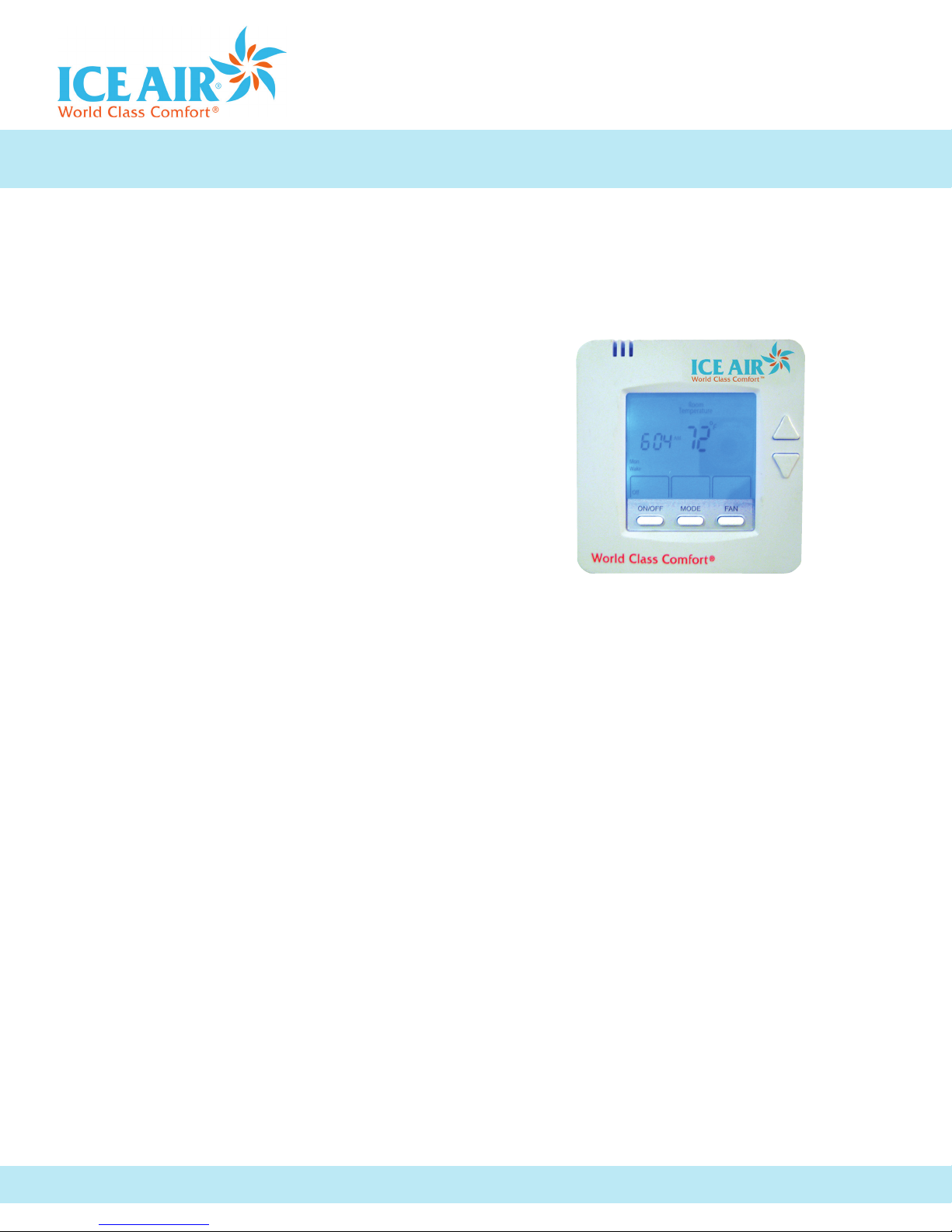
b) Single Stage Digital Auto or Manual Changeover
This thermostat is a single-stage, digital, auto
or manual changeover with a HEAT-OFF-COOL-
AUTO system switch and a fan ON-AUTO switch.
The thermostat has an LCD display with
temperature and set-point(s) in ºF or ºC. The
Thermostat provides permanent memory of
set-point(s) without batteries. A fault LED is
provided to display specific fault condition. The
thermostat provides temperature display offset
for custom applications.
ELECTRICAL DATA
• Ensure that available power is the same voltage and phase as
indicated on the unit serial plate. Line and voltage wiring must
be executed in accordance with local codes or to the National
Electrical Code or in Canada to Canadian Electrical Standards.
• Apply correct line voltage to unit. Disconnect switch near unit
is required by code. Power to unit must be sized correctly and
have dual element class RK5 fuses or HACR circuit breaker for
branch circuit overcurrent protection. Consult the unit serial
plate for current ratings.
• All 208/230V units are wired for 208V operation unless other-
wise specified.
The following physical conditions must be maintained for
proper unit operation:
Unobstructed air flow into and out of the unit room
enclosure (cabinet).
Therefore:
- Do not place any object in front of the discharge grille
(at the cabinet top)
- Do not place plants, fabrics or objects in front of the air
return access door
- Have the unit filter properly cleaned and serviced to prevent
air blockage from dirt and dust within the filter media
• Proper installation and operating environment must be
maintained.
Therefore:
- Do not operate the unit in corrosive environments such
as chemical plants, refineries or salt spray areas.
- Operate only with proper electrical service and protective
circuit breakers or fuses in place.
- Operate only with all components in place and properly
installed.
- In areas of high concentrations of dirt, dust, pet dander
or pollutants, clean the filter often (at least monthly).
- Do not clean the unit with any solvents or cleaning
solutions that may damage the equipment (see
maintenance Instructions for proper cleaning protocols).
- Understand and follow the unit operating instructions
below before using your WSHP equipment.
CONTROLS
ICE AIR Vertical Stack WSHP units are controlled by a state-of-
the-art electronic package that is comprised of a digital control
pad and internal Power Control Board (PCB).
Control Pad

OPERATING & MAINTENANCE MANUAL – VERTICAL STACK WATER SOURCE HEAT PUMP (VWSHP)
5
OPERATING & MAINTENANCE MANUAL – VERTICAL STACK WATER SOURCE HEAT PUMP (VWSHP)
COOLING MODE
• To activate cooling, press the mode button until COOL displays
• Press up/down arrow keys to your desired temperature
• Compressor will cycle when temperature reaches the set point.
After compressor stops, allow at least 3 minutes before restart-
ing (this applies only if you have manually turned the unit off or
reset the thermostat - during normal running conditions, the unit
will automatically allow for the required restart delay)
The temperature reading that is on constant display is the ambient
room temperature.
HEATING MODE
• To activate heating, press the Mode button until HEAT displays
• Press up/down arrow keys to your desired temperature
• The unit will cycle until the set temperature is achieved and then
will continuously cycle to maintain the set temperature.
The temperature reading that is on constant display is the ambient
room temperature.
LOCKOUT SAFETY
All Ice Air WSHP units have its own lockout circuit to shut down the
compressor during an abnormal condition. During unit operation the
compressor will be automatically turned off due to one of these safety
conditions.
• High pressure
• Low temperature
• Condensate overflow
c) Single Stage Manual Changeover
Programmable 5/2 Day
This thermostat is 5 day/2 day programmable (with
up to 4 set-points per day), single stage (1H/1C),
manual changeover with HEAT-OFF-COOL system
settings and fan ON-AUTO settings. The thermostat
has an LCD display with temperature, set-point(s),
mode, and status indication. The temperature
indication is selectable for ºF or ºC. The thermostat
provides permanent memory of set-point(s) without
batteries. The thermostat provides a convenient
override feature to temporarily change set-point(s).
OPERATING INSTRUCTIONS
OPERATION
IMPORTANT NOTE:
Do not attempt to restart the unit in Cooling mode for at
least three minutes after any of these actions:
• TurningtheunitOFF
• ResettingtheTemperatureControltoaWarmer
position
• SwitchingfromCoolingmodetoanyothermode
A
B
88"
C
D
E
62 1
2
"
CASING
CHASSIS
WITH FILTER
ACCESS PANEL
WITH HINGED
DOOR
STEEL DOUBLE
DEFLECTION
GRILLE
REVISIONS
REV.
DESCRIPTION
BY
DATE
01
8/19/2013
A
B
C
D
E
VHPW09-15
16 17
18 7/8 18 3/8 41 3/8
VHPW18-24
18 20
20 7/8 21 3/8 45 1/2
VHPW30-36
22 24
24 7/8 25 3/8 45 1/2
6
4
3
2
1
SAB-9237
5
7
8
B
SAB-9237
01
-
-
Third Angle Projection
DATE:
MODEL BY:
365.34
MATERIAL:
08/16/13
VP
ICE-AIR LLC.
80 HARTFORD AVENUE
MOUNT VERNON, NY 10553
PROPRIETARY AND CONFIDENTIAL
WEIGHT (LBS):
FINISH:
N/A
DRAWING BY:
DATE:
TITLE:
SIZE
DWG. NO.
REV
SCALE: NONE
UNLESS OTHERWISE SPECIFIED:
SHEET 1 OF 1
DO NOT SCALE DRAWING
V-WSHP GENERAL ASS'Y (BASIC)
DIMENSIONS ARE IN INCHES
TOLERANCES:
FRACTIONAL
1/32
ANGULAR: MACH
BEND
1
TWO PLACE DECIMAL
.03
THREE PLACE DECIMAL
.015
This drawing is the intellectual property of
Ice Air,LLC
and
consists of confidential data belonging solely to
Ice Air,LLC
.
The sharing of this data with you does not constitute a
license to share this data with any third party, which is
strictly prohibited without Ice Air's prior written consent.

OPERATING & MAINTENANCE MANUAL – VERTICAL STACK WATER SOURCE HEAT PUMP (VWSHP)
6
MAINTENANCE & SERVICE
MAINTENANCE OVERVIEW
Your ICE AIR WSHP unit is designed to provide you with many years
of efficient, trouble-free comfort conditioning service. To ensure
equipment longevity and efficiency, please make sure that the
following simple maintenance procedures are followed.
This manual assumes that your WSHP unit has been installed by a
qualified installation professional, and is operating properly prior to
maintenance service.
• Have your unit periodically inspected by a properly trained
service professional or building maintenance staff person. The
unit should be checked for the safe and proper functioning of
all of its systems at least once a year. The following recom-
mended maintenance procedures should be carried out only by
trained personnel with strict adherence to the safety guidelines
outlined at the beginning of this manual. These procedures
MUST be followed to ensure your safety and the safety of the
person maintaining the equipment.
FILTER
ICE AIR WSHPs are equipped with a washable/reusable Filter.
It is recommended that you clean the indoor air filter after
every 350 to 400 hours of unit operation - more frequently
if the unit is running in an environment of high dust, pet
dander or other pollutants in the indoor atmosphere.
• Filter inspection: The filter is located at the bottom of your unit.
To remove unit slide it out towards you.
• To reinstall place filter under the unit and slide back in to the
filter rack
Filter Cleaning:
To clean your filter use luke warm water with a biodegradable
cleaner rinse and allow to dry completely before installing back
to unit. (As an alternate cleaning method,
the filter may be cleaned on both sides
using a vacuum cleaner with a soft brush
type attachment.)
DO NOT OPERATE UNIT WITHOUT
FILTERS. This practice will damage and/
or seriously impair the performance of
your unit and could void your Warranty.
CHASSIS CLEANING
Evaporator Coil and Drain Pan/Drain Hoses:
To access the components within the chassis of the unit,
disconnect unit power and then remove the unit Access Door
by unscrewing the retaining screws that hold the door in place
(use a Phillips head driver). You will then have access to the
unit chassis and components:
CAUTION: to prevent injury or death due to electrical shock or contact with moving part,
turn off the disconnect switch before servicing this unit.
IMPORTANT NOTE: It is not the intent of this maintenance manual to correct any installation deficiencies. If you have any
doubt about the proper initial installation (or reinstallation after servicing) of your WSHP unit(s)- noisy or inefficient unit
operation,frayed or damaged electrical connections, improper unit appearance, etc. Please contact a trained servicer or building
maintenance staff immediately.
DO NOT OPERATE ANY EQUIPMENT THAT DOES NOT APPEAR TO BE FUNCTIONING PROPERLY!
IMPORTANT NOTE:
The power MUST be disconnected before carrying
out any of the following cleaning!

OPERATING & MAINTENANCE MANUAL – VERTICAL STACK WATER SOURCE HEAT PUMP (VWSHP)
7
OPERATING & MAINTENANCE MANUAL – VERTICAL STACK WATER SOURCE HEAT PUMP (VWSHP)
Compressor:
Annual check should be performed to detect potential
problems.
• Amperagedrawshouldnotexceednormalfullloadampsindicated
in the performance table. (Consult installation manual for details).
Heat Exchanger:
Water coil maintenance is not required. If the unit installation is
located in a system with water problem history it is best to
establish a periodic maintenance program. It is the building’s
responsibility to maintain a water system that should provide
your unit with treated and filtered water to keep water
flowing freely thru your equipment. Generally if the water
flow exceeds 3 gpm per ton the water velocities should keep
your coil free of scaling and debris that could lead to coil
erosion and fouling up.
General Unit Inspection:
Visually inspect unit at least once a month. Pay special attention to
hose assemblies and connections. Repair any leaks and replace
deteriorated hose immediately to avoid potential costly damage to
your property due to component failure.
Evaporator Coil:
Check the coil for cleanliness and uniformity of fins. If the coil
is dirty, vacuum clean with a soft brush attachment. This is the
only form of cleaning that should be carried out within an
apartment. If the coil requires additional cleaning, the unit
must be removed from the wall cabinet and cleaned using
compressed air and / or washed. These operations MUST be
carried out in a facility properly equipped to handle this type of
work in a safe and professional manner. Do not carry out this
cleaning in a finished apartment or office area.
Drain Pan/Drain Hose Cleaning:
The condensate pan is located under the unit chassis. Check
the visible section of the interior of the drain pan for any
buildup of dirt or condensate water.
Wash annually to remove all dirt build-up. Check condensate
drain pan for algae growth every 2 to 3 months. If algae growth
is apparent consult a water treatment specialist for treatment.
Drain Hose:
Check drain hose for leaks and blockage to eliminate potential
problems.
Evaporator Motor and Blower Assembly:
If there is evidence of dirt or dust build-up the evaporator
motor or blowers, they should be cleaned either by vacuum
cleaning (if working in an apartment) or by removing the unit to
a workshop location and cleaning with compressed air. Always
obey safety guidelines for using compressed air in this latter
case. Your ICE AIR WSHP has permanently lubricated motor
bearings that do not require additional lubrication. Blowers and
motor are factory assembled for quiet performance – if there is
any excessive noise and vibration from this assembly, it should
be serviced by a qualified technician.

80 Hartford Avenue, Mount Vernon, NY 10553 | Tel: 877-ICE-AIR-1 (877-423-2471) | Fax: 914-668-5643 | email: service@ice-air.com
www.ice-air.com | © 2013 by ICE AIR, LLC
TROUBLESHOOTING
1. If unit is not operating, conduct the following checks:
• Check the electrical connections
• Check the voltage and current against the electrical
specifications on the unit nameplate
• Look for wiring errors. Check for loose screw connections
in both line and low voltage terminals
• Check the water supply piping for proper water
connection
• Check for dirty filters
• Check indoor fan for proper operation
• Check that unit did not cycle off due to improper
thermostat settings
• Check for fault codes on the control board consult the
troubleshooting guide.
2. If checks above fail to reveal operating problem:
If the unit still do not operate after reset, contact trained
service technician to conduct full unit diagnostics and repair to
equipment. Record any unit that does not operate noting the
unit serial number on your report
BOARD TROUBLESHOOTING TABLE
Fault Description Board LED Code
Yellow Green Red
Normal OFF ON OFF
High Pressure Lockout OFF OFF FLASH
Low Pressure Lockout FLASH OFF OFF
Air Side Freeze-up Protection FLASH OFF FLASH
Waterside Freeze-up Protection FLASH ON OFF
High Water Temperature Protection FLASH OFF ON
Over/Under Voltage Protection OFF OFF ON
Condensate Overflow Protection ON OFF OFF
Low Water Temperature Protection ON OFF FLASH
Table of contents
Other ICE AIR Heat Pump manuals
Popular Heat Pump manuals by other brands

York
York AFFINITY YZB brochure

Trianco
Trianco Activair S1200 User, installation, commissioning & servicing instructions

Madimack
Madimack ECO user manual

Gree
Gree NCHS1D owner's manual

Daikin
Daikin Altherma 3 H F+W EABH16DF9W User reference guide

Carrier
Carrier 50TJQ004-007 Installation, Start-Up and Service Instructions

Dimplex
Dimplex SI 7ME Installation and operating instructions

Nibe
Nibe Fighter 200P Installation and maintenance instructions

Zodiac
Zodiac Z550iQ Instructions for installation and use

Nibe
Nibe F1345 Series operating manual

Trane
Trane 4TTA4 Installation and operation manual

Airwell
Airwell AWSI-DED076-N11 Service manual