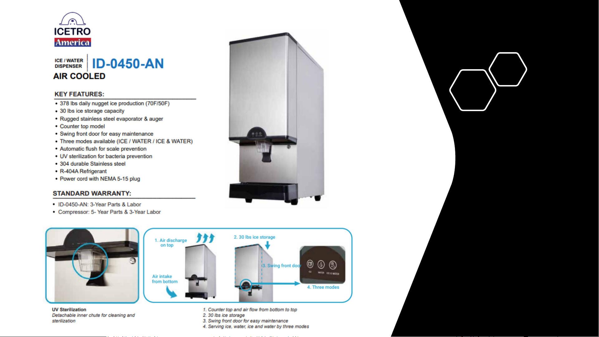
icetro ID-0450-AN Supplement

ID-0450-AN INSTALL & SERVICE MANUAL

ID-0450 Specs
2

ID-0450 Specs
3

Receiving & Unpackaging
Dispensers
All equipment leaves our distribution points in new condition.
When receiving new equipment, please pay close attention to the packaging for
any damage to the crating. If there appears to be any exterior damage, please
either note the damaged on the delivery bill of lading OR refuse it.
Failure to note damage on BOL or refuse damaged equipment means
that the receiver accepts all liability for damaged equipment.
Damage
4

Proper Installation
ID-0450
5
Installation, Start Up, and Check
Please double check these items before install & start-up before calling for service.
(These items are not covered under your Labor Warranty)
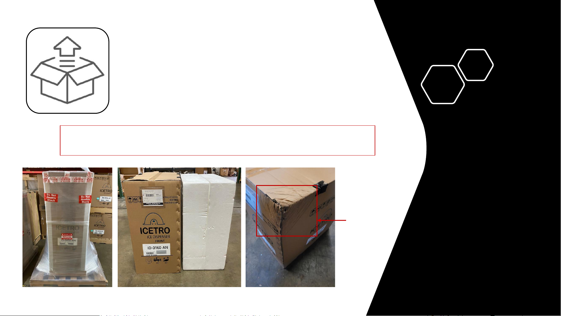
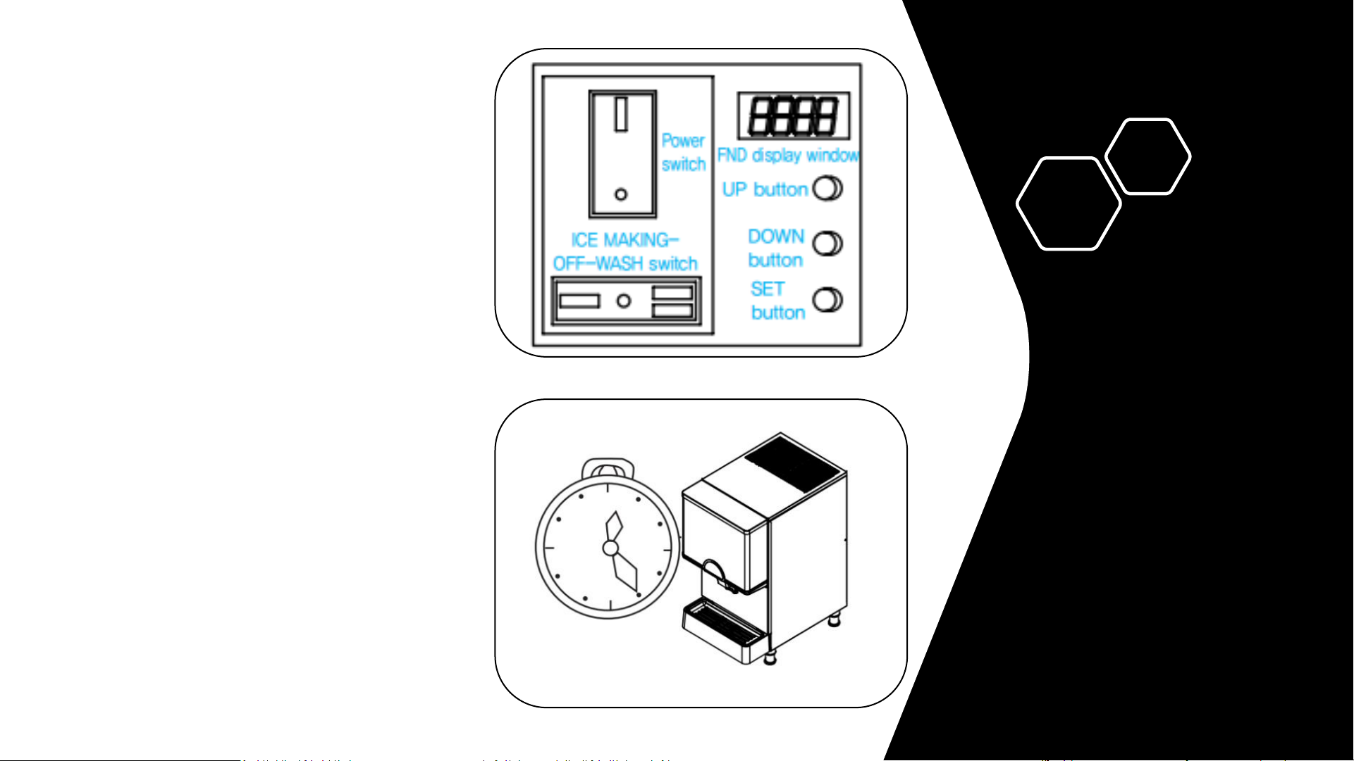
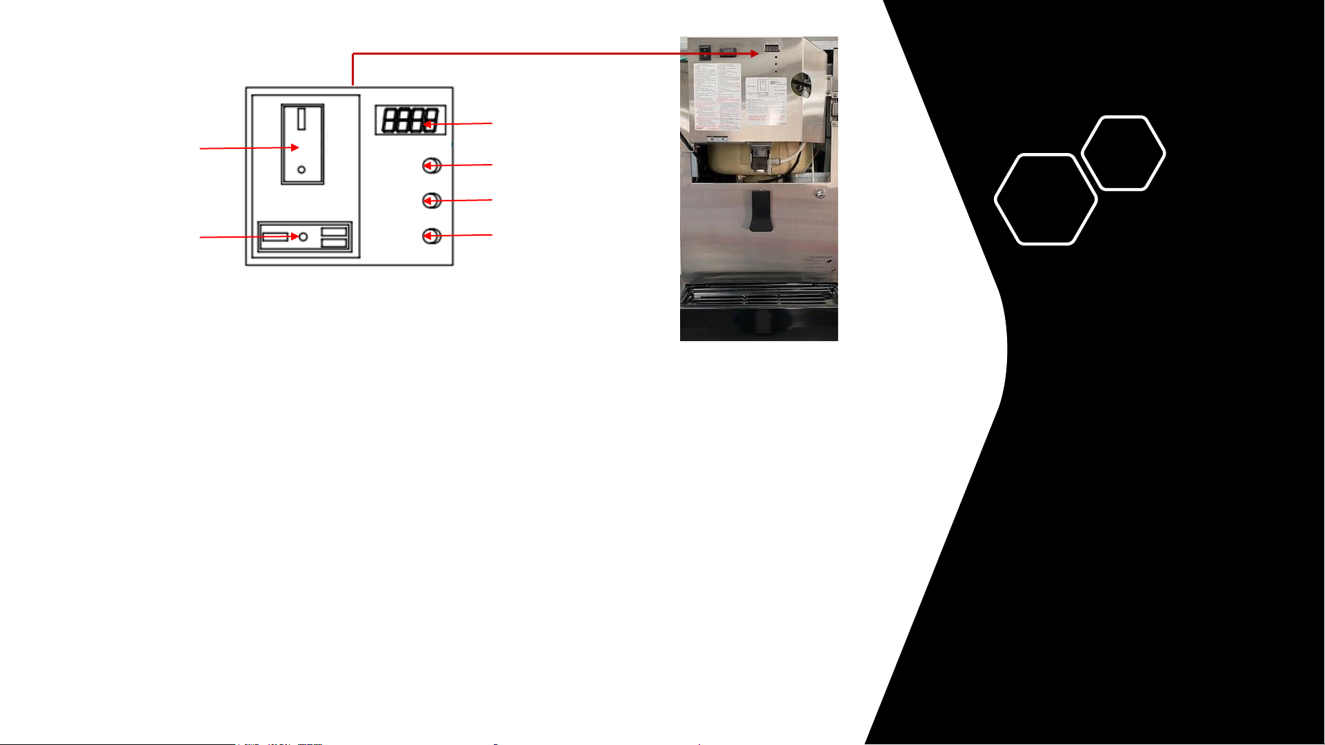
1. Has all tape and packing materials been removed from Machine?
2. Is the unit installed in a location that is away fromheat generating equipment or direct sunlight?
3. Is the unit level front to back and side to side? This unit is equipped with legs which are adjustable from 3.25” – 4” in height.
4. Is the correct electrical power provided? Ensure the unit has the specified voltageand amperageandis on a dedicated circuit. Do not use a
drop cord or power strip with any ice machine. This could cause a voltage drop and compensatoryamperage spike or cause the circuit
breaker to trip.
5. Check drain line pipe sizes. Insurethey are ¾ inch and line drops ¼ inch per foot of run to insure both machine and bin drainage is
effective.
6. Is water supplied to the unit? Water Line size, 3/8 inch, must be supplied to ensure sufficientwater flow is always available. Required
water pressure is 20 psi minimum and 80 psi maximum. This unit is designed to work with water temperatures of 50°F -90°F.
7. Is the unit installed in an area with sufficient ventilation on top for proper rejectionof condenser heat and maintenance? The manufacturer
requires 30” of clearance above the unit for maintenance and service. Never block the top vents on the unit! Fresh air is taken in from the
bottom and dispelled from the top.
8. This unit is designed to work in ambient air temperatures of 50°F -100°F.
9. Scale or Mold build-up can affect the sequenceof operation and production. Is a water filter installed? We recommend our exclusive
Citryne Pro Ice Filtration for the best results. Scale will increase operating costs and reduce or shut down the machine’s
performance.
10. Do not install this unit outdoors.

Proper Installation
ID-0450
Ensure the power switch is set to ‘ON’
and the ICE-OFF-WASH switch is
set to ‘ICE’.
Ice will begin to enter the hopper after 3
minutes of the compressor & condenser
fan being energized.
You can begin to use the ice 10 minutes
after that and the hoper will be full
of ice after about 70 minutes.
6

Error codes are also listed in the owner’s manual.
Main Power
Switch
ON-OFF-WASH
Switch
Up Button
Down Button
Set Button
FND Display
1) Forced Drain Function: (Must be used to prevent water from freezing in winter
storage.) Please also use this function to drain water before cleaning any internal
parts.
●Turn on the main power switch. Press the “DOWN” + “MODE” buttons simultaneously for 3 seconds on the
FND panel. Water will then purge from the water sump for 30 seconds.
2) Automatic Drain Function:
●Turn on the main power switch. Press the “MODE” button until F. 5 is displayed on the FND.
●The 1st & 2nd digits displayed is the drain time (2 seconds) and is adjustable in 1 second increments, up to
99 seconds.
●The 3rd & 4th digits displayed is the drain interval (1 hour) and is adjustable in 30 minute increments from
0.5 to 9.5 hours
3) Initial Water Draining Function:
●Turn on the main power switch. Press the “MODE” button until F. 4 is displayed on the FND.
●The 1st & 2nd digits displayed is the drain time (30 seconds) and is adjustable in 1 second increments, up to
99 seconds.
●The 3rd & 4th digits displayed is the number of repetitions (3 times) and is adjustable from 1 to 9 times.
Flexible Numeric Display
(FND) on ID-0300
7

ID-0450
PCB & FND
PCB connections are clearly marked and have LEDs to indicate to the
technician when certain parts are powered.
By separating the main PCB from the FND, Icetro has managed to keep
the cost of a replacement PCB lower than all its competitors!
Display
Up Button
Down Button
Set Button
8
Main
Power
Compressor
Agitator
Condenser
Fan Motor
UV
LED
24v Power
Drain Solenoid
H20 Inlet
Solenoid
H20 Dispense
Solenoid
FND
PCB
Thermistor Sensors
Door
Buttons
Bin Switch
Water Level Sensor
Mode Switch
Reset
Button
Dispense Lever
Dip Switches
FND Board

ID-0450 Exposed
Dispensing solenoid valve only opens when dispensing ice, preventing airborne
bacteria from growing inside of the ice hopper!
Our dispensers also utilize light! 9
Ice Dispensing
Solenoid
Front
LED/UV Light
Ice Hopper
Agitator Motor
Ice Hopper

ID-0450 Exposed
Easy access the condenser, fan motor, & more
for easy service & diagnosis!
Condensers bring in air from the bottom and
exhausts from the top.
10
Back
Secondary Bin
Switch
Water Dump
Valve
Water Reservoir
Evaporator
Water Inlet
Solenoid
Condenser
Fan Motor
Water Dispense
Solenoid

ID-0450 Exposed
Easy access the other major components, such as the txv, gear motor, water
reservoir, thermistors and more!
11
Right Side
Front Door
Svc Port Condenser
Auger Motor
Compressor
Liquid Line
Thermistor
TXV
Auger Motor
Capacitor
Suction Line
Thermistor

ID-0450 Exposed
ID-0450
Ice Hopper
Cover
Primary Bin SwitchBin Switch
Magnet
Extruder
Cover
Extruder
Cap/Breaker
Here you can clearly see how the evaporator feeds ice up to the extruder cap/breaker and then pushes
it to the front of the machine, where the hopper stores the ice for consumption.
The ice hopper uses a separate motor from the evaporator for agitation and dispensing. 12

Extruder Heads
& Bearing
Spiral circular cutting blade designed to reduce gearbox torque
and provide greater durability.
Pin cut spring insertion in
bottom of flight.
Spline cut fits into reverse spline
coupling on gear box shaft, which
ensures no imbalance in
bottom bearing.
Spring loaded carbon/ceramic
mechanical seal.
Tapered flight
reduces torque.
13

Extruder Heads
& Bearing
Nugget Extruder
Nugget Extruder Head
•Carbon bearing is pressed inside of extruder head.
•No grease or maintenance to prevent major
mechanical breakdowns.
•Simply check extruder/bearing & replace if
required.
Extruder with Carbon
Bearing Pressed Into Place
14

Maintenance & Leaks
Visually inspect all hex head bolts
holding lower housing assembly
to evaporator barrel for leaks.
Drains have been enlarged to
prevent overflow & scale
buildup on critical parts.
Use caution during reassembly
to ensure new bolts are cross
tightened evenly.
15

Maintenance & Leaks
Poor maintenance, leaking gaskets/bolts, or a plugged drain can destroy a machine: If bolts
at the top extruder or lower housing assembly leak, scale can build up on the urethane
insulation, the lower housing assembly, and/or the gear box and destroy those parts.
When removing bolts, new o-rings and/or new bolts with o-rings should be used.
If bolts are not tightened properly (or o-rings damaged) the leaks above will occur.
Should the drain pan’s drain line
become plugged, it will overflow and
cause scale to greatly damage unit.
16

Wiring Diagram
17

Dispenser Float Switch
Float Sensor Water valve
operation Physical state
High water level
sensor
Low water level
sensor
0(Close) 0(Close) ON Water tank Empty
0(Close) 1(Open) The current
operation continues.
The water only fills to the lower
part.
1(Open) 0(Close) The current
operation continues.
No definition
(Physically impossible)
1(Open) 1(Open) OFF Water tank Full
Water valve operates separately according to the water level sensor
Water tank
Empty
The water
only fills to
the lower part.
Water tank
Full
18

Detailed Operation
Sequence
Item Contents
Initial power-up.
ICE-OFF-WASH switch is in
The ‘Ice’ position.
1.
Water inlet solenoid energized for 20 seconds for initial water reservoir fill.
2.
Dump solenoid energized for 30 seconds & then water inlet solenoid energized for
10 seconds. (This occurs 3 consecutive times)
3.
Gear motor is energized.
4.
After 60 seconds of the gear motor being energized, the compressor & condenser
fan motor are both energized.
5.
Ice begins to enter the ice hopper after 3 minutes of the compressor being
energized.
Ice Hopper Full
1.
When bin switch opens for 2 consecutive seconds, the machine is recognized as
being full and the compressor & condenser fan motor are de-energized.
2.
Gear motor continues to run for 60 seconds & is then de-energized.
Ice Hopper Low
1.
When bin switch closes for 2 consecutive seconds, the machine returns to the ice
making mode and the gear motor is energized.
2.
After 60 seconds of the gear motor being energized, the compressor & condenser
fan motor are both energized.
Water Inlet Solenoid
1.
Energized when low level/high level float switch is in the NC (down) position.
2.
De-energized when high level float is in the NO (up) position.
3.
Triggers error code (Er15) when the high-level float is not detected after operating
for 60 seconds.
Gear Motor
1.
Energized when the high-level float is detected.
2.
Stops after a 60 second delay when bin switch opens.
3. After 1 hour of no operation, gear motor will energize for a 12 second agitation. This
will continue every hour until the bin switch closes and normal operation resumes.
Compressor
1.
Energized 60 seconds after the gear motor is energized.
2.
Stops immediately when the bin switch opens, indicating the ice hopper is full.
19

Item Contents
Dump Solenoid
1.
Energized for 2 seconds after 1 hour of machine operation.
2.
This is repeated indefinitely until the power is turned off.
Dispense Lever Operation
1.
Chose a dispensing option (ice, water, or ice + water) and place cup against lever to
engage it.
2.
If dispensing lever is released and immediately engaged again, there will be a 2
second delay before any solenoids will activate, regardless of which mode is
selected.
3.
Once the dispensing lever is disengaged, all operation stops immediately.
Ice Dispensing Solenoid
(Ice Mode)
1.
Energized when the dispensing lever is engaged, and the N/O switch is closed.
2.
De-energized when the dispensing lever is released, and switch opens again.
3.
Maximum operating time is 20 seconds by default but can be changed.
4.
If ice hopper is full, the gear motor will also energize to dispense ice.
Ice & Water Dispensing Solenoid
(Ice + Water Mode)
1.
Ice & water solenoids are both energized simultaneously when the dispensing lever
is engaged, and the N/O switch is closed.
2.
Maximum operating time of the ice solenoid is 5 seconds by default but can be
changed.
3.
Maximum operating time of the water solenoid is 3 seconds by default but can be
changed.
4.
If ice hopper is full, the gear motor will also energize to dispense ice.
Detailed Operation
Sequence
20
Other manuals for ID-0450-AN
1
Table of contents
Other icetro Dispenser manuals
Popular Dispenser manuals by other brands

Sanipex
Sanipex AquaEco BDA-AQU-612 Series installation guide

VOCA
VOCA TC-X Installation instruction

Air Wolf
Air Wolf Lobo Series manual

Global Industrial
Global Industrial 641519 Assembly instructions

Curtis
Curtis GEMX IntelliFresh FreshTrac GEM3XIFT user guide

Polar Electro
Polar Electro CF760 instruction manual