ICI TDL 300 User manual

We are IR™
INFRARED CAMERAS INC.
2105 W. Cardinal Dr.
Beaumont, TX 77705
Phone: (409) 861-0788
Toll Free: (866) 861-0788
TDL 300 User Manual
Handheld Laser Methane Detector

2 3
The contents of this user manual are proprietary to ICI. Copy,
translation, storage in a database or retrieval system, or in any
electronic, reproduction, recording means or ways to spread this
manual is prohibited without written permission of ICI.
Contact information is as follows:
Infrared Cameras Inc.
2105 W. Cardinal Dr.
Beaumont, TX 77705
Hours: Monday - Friday 8:00 AM to 5:00 PM CST
Phone: (409) 861-0788
Toll Free: (866) 861-0788
Fax: (409) 866-7229
E-mail: [email protected]
Copyright About
ICI manufactures complete
infrared systems and
technology. We provide
engineering, software,
and OEM solutions. Our
customers are among the
largest of the Fortune 500
and they rely on us for
infrared equipment and
thermography training,
offered through the
Infrared Training Institute.
In addition to providing
custom germanium, silica,
and sapphire optics, we
build enclosure windows
as well as custom pan and
tilt units. Customizable
explosion proof systems
are available.
Our knowledge and
experience stems from
years of using infrared
imaging and temperature
measurement instruments
to provide solutions to
managers, engineers,
scientists, inspectors and
operators in space, power
companies, the medical
field, pulp and paper, food
handlers, research and
development, and various
process industries. You
can see our products and
services used in industrial,
commercial, and
government applications
worldwide.
Additionally, our ICI 7320
was awarded “Product of
the Month” by NASA*.
Originally named Texas
Infrared (still DBA),
Infrared Cameras Inc. has
been in business since
March, 1995.
We thank you for your
dedication and support.
The following is a partial list of our customers:
Air Liquide
American Aerospace
Arizona State University
Baker Instruments
BASF
Bergquist
Boeing
BP Solar
Chevron Pipe Line
Columbia University
Dane Electric
Dartmouth College
Dell
Dow Chemical
Exxon/Mobil
Entergy
Foxconn
Firestone Polymers
General Electric
Georgia Pacific
Goodyear
Google
Harvard Medical School
Honeywell
Indiana University
Keystone Scientific
Kinder Morgan
Lockheed Martin
Los Alamos National Labs
Johns Hopkins
Louisiana Pacific
Mabry Foundry
Marathon Oil
Max Planck Institute
MD Anderson
Motiva
NASA
Nissan
Nokia
Novatech Engineering
Orbital Sciences
Panasonic
Paragon Films
Purdue University
Raytheon
Reliant NDT
Rosewell Park Cancer Institute
SA Robotics
Sea Drill
Space-X
Stanford University
Tesla Power
Texas A&M University
Texas Instruments
*Volume 33 No. 2, February 2009 edition of NASA Tech Briefs

4 5
Thank you for choosing your device from Infrared Cameras Inc.
(henceforth referred to as ICI).
To use your new equipment safely and effectively please read the
following instruction manual before turning on or using the device.
You must operate the device according to the operating steps to
avoid damage, misuse, or accidents.
ICI is NOT responsible for the consequences resulting if the
user does not install, operate, repair, or replace components in
accordance with this manual. ICI will prepare and revise this user
manual to ensure its accuracy and reserves the right to make
improvements and or changes without prior notification. The
pictures in this instruction are for function description only.
Please keep this manual in order to check maintenance scheduling
(if applicable). Contact information is as follows:
Infrared Cameras Inc.
2105 W. Cardinal Dr.
Beaumont, TX 77705
Hours: Monday - Friday 8:00 AM to 5:00 PM CST
Phone: (409) 861-0788
Toll Free: (866) 861-0788
Fax: (409) 866-7229
E-mail: [email protected]
Using the Manual
1. Before using this product, check the accessories according to
the product list, product certification, and user warranty card.
If accessories are missing or broken, contact the distributor or
manufacturer immediately.
2. Within twelve months from the date of sale, if the user abides by
the storage, transportation, and use requirements, the user can
obtain free maintenance with warranty.
3. Damages caused by the violation of operating regulations and
maintenance not sanctioned by this manual or our designated
service department or caused by problems due to force majeure,
will incur maintenance charges.
4. Before product maintenance, show your product warranty card
to the technician in the service department. If you cannot show a
warranty card our company will charge for maintenance.
5. If you are not satisfied or have any questions or complaints with
products and services we offered, including product quality,
technology, installation and maintenance, customer service, fees
and other issues, contact us promptly.
User Service Guide

6 7
Safety
It is essential for users of this device to read this manual in its
entirety before installation, operation, and maintenance. Pay
attention to the warnings and notices.
• When you open the box, check the product shell for cracks or
missing parts. If the equipment is damaged or has missing parts,
do not use the device. Contact ICI immediately.
• Before operation, the user must abide by local regulations and
on-field operation procedures.
• This device uses a green visible spotter laser that is a Class 3R
laser. Do NOT stare directly into the laser beam or point into
other people’s eyes.
• Do NOT aim the device at the sun to avoid damaging the device.
• Do NOT expose the detector to electric shock, electromagnetic
fields, or continuously severe vibrations.
• Check the battery before using the instrument and make sure the
connection is correct.
• Charge the battery with the customized charger from ICI.
• Do NOT charge, uninstall, or replace the device’s batteries in
hazardous areas.
• Do NOT charge the device in hazardous environments. Charge
indoors in a safe and dry environment.
• If the detector is left unused for long periods of time or is to
be packed away for long-term storage, take out the battery and
recharge to full capacity.
• Do NOT store batteries in device.
• Do NOT short-circuit the batteries.
• The device uses Lithium-ion batteries. Do NOT combine with
household batteries.
• Broken batteries should be handled by qualified recyclers or
processors of dangerous goods.
• Do NOT drop the device from extreme heights or expose the
device to severe vibrations.
• Installation of the device must abide by local requirements of
electrical installations, otherwise it may lead to personal injury.
• Use dust blower to blow away dust and debris from the optical
lens, then use medical gauze or equivalent non-abrasive lens
tissue with a small amount of alcohol.
• Do NOT repair, adjust, or change the components.
• NO attempt should be made to repair the device. Should the
detector not work properly, or indicate an error warning, refer to
the troubleshooting section of this manual.
• Only a qualified TDL 300 repair technician should attempt to
repair or adjust the detector.
• Read and fully understand the operation manual before operation
or maintenance of the device.

8 9
Symbol Denition
Before continuing or using the device the operator should be
familiar with the symbols that may appear in this manual:
Warning - A cautionary indicator of hazards that may result in a
major accident or personal injury. Use caution.
Notice - A cautionary indicator of potential personal injury, property
loss, and hazards. Use caution.
Remark - Notes, use tips and additional information to properly
operate device.
1. Overview --------------------------------------------------------------------------------------
1.1 Main Function & Technical Features ------------------------------------
1.2 Main Technical Specification -----------------------------------------------
1.3 Product Introduction ----------------------------------------------------------
2. Principle Introduction -------------------------------------------------------------------
2.1 Detection Principle -------------------------------------------------------------
2.2 Glossary & Definitions --------------------------------------------------------
3. Operation Instruction -------------------------------------------------------------------
3.1 System Composition ----------------------------------------------------------
3.1.1 Battery Pack -----------------------------------------------------------
3.1.2 Charger -----------------------------------------------------------------
3.2 Operation Instruction ---------------------------------------------------------
3.2.1 Power On/Off ---------------------------------------------------------
3.2.2 Normal Display Menu ---------------------------------------------
3.2.3 Concentration Alarm Menu -------------------------------------
3.2.4 Malfunction Alarm Menu -----------------------------------------
3.2.5 Volume Setting Menu ---------------------------------------------
3.2.6 Alarm Threshold Setting Menu --------------------------------
3.2.7 Spotter Laser Power On/Off ------------------------------------
3.2.8 Alarm Light Indicator ----------------------------------------------
3.2.9 SIM Card ----------------------------------------------------------------
3.3 Battery Charging ----------------------------------------------------------------
3.4 Wavelength Method -----------------------------------------------------------
4. Measurement Method -------------------------------------------------------------------
5. Maintenance --------------------------------------------------------------------------------
6. Troubleshooting Guide -----------------------------------------------------------------
7. Notes -------------------------------------------------------------------------------------------
8. Contact ----------------------------------------------------------------------------------------
Contents
10
11
12
14
16
16
17
19
19
19
20
21
23
23
24
24
25
25
26
26
27
28
29
30
32
34
36
37

10 11
1.1 Main Function & Technical Features
• Remotely Detect Gas;
• Distance: 50 m;
• Small Size;
• Lightweight, easy to carry;
• Detects Methane, avoids interference from water vapor, vehicle
exhaust, and other hydrocarbon gases;
• High Sensitivity;
• Fast Response, no delay alarm;
• LCD Screen with Visual Data Display;
• 2 Real-time Displays: Waveform Diagram and Figure;
• Optional Range: PPM.M, LEL.M, and VOL.M;
• Damage Resistant;
• Low Power Consumption;
• Low Power Indicator;
• Visual and Audio Alarm;
• Adjustable Volume;
• Intrinsically Safe Design.
1. Overview
The Tunable Diode Laser 300 (TDL 300) is an advanced handheld
remote laser gas detector developed by ICI. This solution adopts the
most advanced non-contact and remote technology in the world,
allowing inspectors to see gases in places they cannot reach. The
leakage point and source can be located and found accurately and
quickly, improving work efficiency and reduced labor cost.
TDL 300 utilizes Tunable Diode Laser Absorption Spectroscopic
technology, making it highly sensitive and quick to respond to
input. It only detects Methane while filtering out other hydrocarbon
gases interference.
Our device is superior for inspections of gas pipelines, oil refineries,
chemical plants in petroleum and the petrochemical industry,
metallurgy, power plants, or any place where Methane leaks occur.
The device is powered by a lithium-ion battery with low power
consumption that has a long life.
The software is intuitive and user-friendly with visual and audible
alarms.
The design, production, and inspection refers to national standards
as follows:
GB3836.1-2010
« Explosive atmosphere Sector 1: General Requirements »
GB3836.4-2010
« Explosive atmosphere Sector 4: Intrinsically Safe “i” »
GB12476.4-2010
« Combustible dust environment with electrical device Sector 4:
Intrinsically Safe “iD” »
This Product is reviewed and inspected by legal authorities
designated by the state authority, and gets type approval.

12 13
• The sensitivity to gas relies on the distance of the device to the
target, and the reflective surfaces in the area
• The device uses “Methane Column Integral Concentration” as the
measurement unit (ppm.m); example:
ppm.m = Methane Concentration (ppm) x gas plume thickness
ppm = parts-per-million
1.2 Main Technical Specification
Gas CH4
Sensitivity Distance≤10mSensitivity:5ppm.m
Distance≤25mSensitivity:10ppm.m
Range 0 ~ 50000 ppm.m
Distance 80 m
Response Time T90 < 0.05S
Temperature -20 °C ~ 50 °C
Humidity 0 % ~ 99 % RH (No Dews)
Storage Temperature -20 °C ~ 60 °C
Explosion-Proof Type Intrinsically Safe
Explosion-Proof Grade EX ib IIB T4 Gb
Ingress Protection IP54
Weight 1.3 kg
Voltage DC 3.7 V (LIC18650-22 3 Batteries)
Display LCD Screen
Operation Time 8 Continuous Hours
Alarming Method Visual & Audible Alarm
Alarm Threshold Adjustable
Laser Safety Detection: Class 1, Spotter: Class 3R
Accessory Battery Charger, Shoulder Strap

14 15
1.3 Product Introduction
TDL 300 adopts a transceiver optical design. The remote detector
will send two laser beams; the detector laser is invisible and the
spotter laser is visible.
After pressing the trigger, the device will automatically begin
detection and the spotter laser will begin to flash. When you release
the trigger, it will stop detecting and the spotter laser will close.
The device will enter dormant mode and then standby mode after a
period of no operation. When the operator presses the trigger, the
TDL 300 will turn on automatically and continues detection.
Do not stare directly into the laser and to not aim the laser into
other people’s eyes.
When the device is in detection status, it will display the Methane
concentration on the LCD screen. If a leak is detected that exceeds
the alarming threshold an alarm icon displays on the screen and an
alarm sound can be heard.
Improper operation, i.e. being to far from the target or pointing
the detector at a bad angle, may cause false alarms or no alarms
to sound. Please move to the proper distance or angle in order to
perform inspections.
The TDL 300 has environmental durability, and insignificant
amounts of dust will not influence the sensitivity and detection
range.
The device is powered by a lithium-ion battery and can work for 6
hours under normal conditions. Standard packaging includes two
battery packs. When one battery pack is depleted, change to the
other battery pack in a safe area.
• The Spotter laser is a Class 3R laser. Do NOT stare directly into
the beam or point the beam into other person’s eyes.
• Do NOT aim the spotter into the sun to avoid damaging the
device.
• Only charge the battery using the customized charger from ICI.

16 17
2.1 Detection Principle
The TDL 300 adopts advanced tunable diode laser absorption
spectroscopy (TDLAS) technology combined with DSP digital signal
processing techniques. This detection method uses wavelength
scanning and tuning characteristics of semiconductor laser diodes
as well as the absorption characteristics of Methane to eliminate
cross interference. DSP allows digital circuits for signal generation,
analysis, and processing to assist the anti-interference capability,
improve stability, and produce repeatable results.
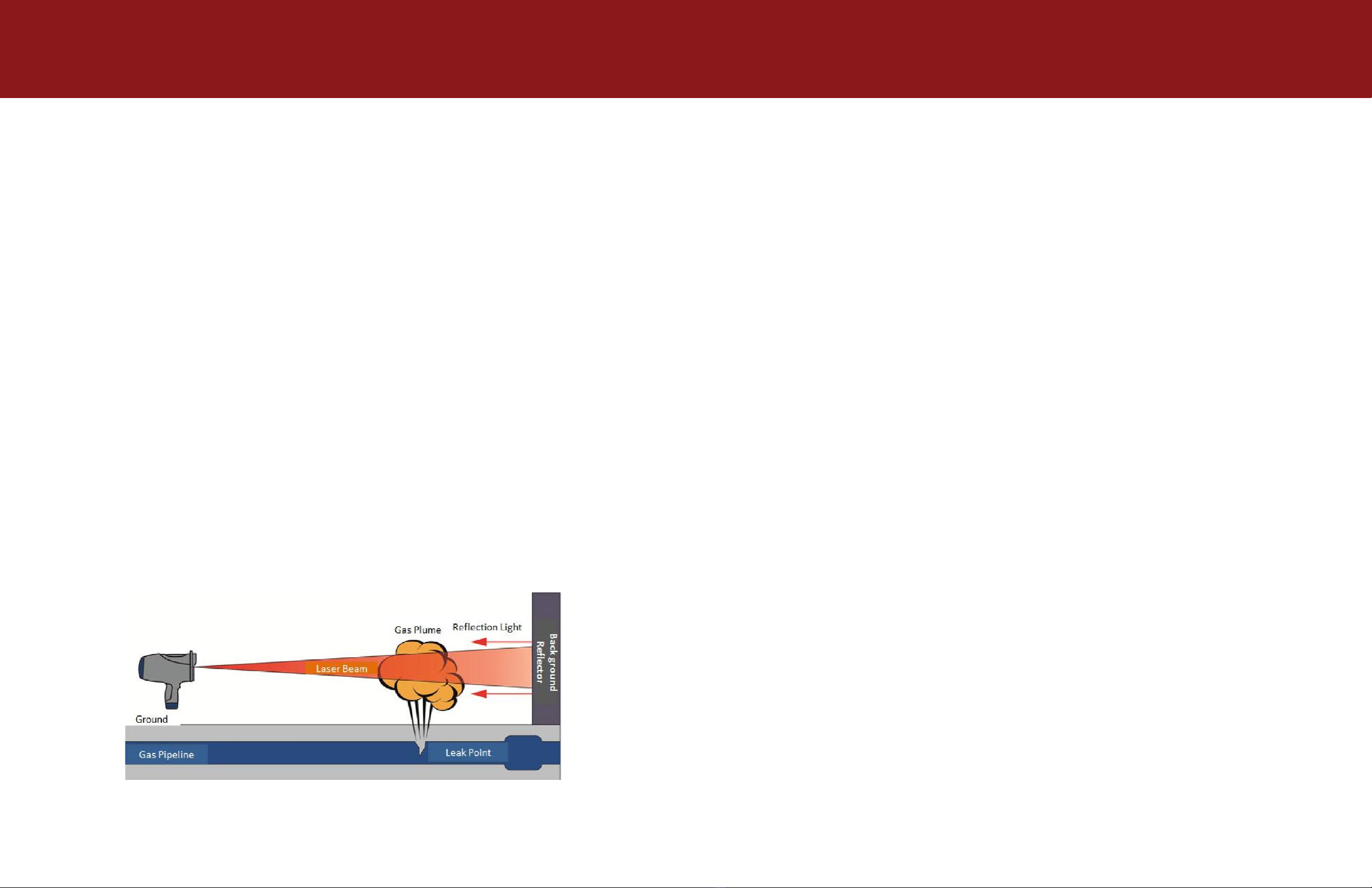
When the laser of the TDL 300 is aimed at the target gas pipeline,
part of the laser beam is absorbed by leaking Methane. The laser
beam returns after being scattered or hitting a barrier behind the
gas. Returning light is collected by an optical lens, and received by
a highly sensitive InGaAs detector. After the signal is processed, gas
concentrations are displayed on the LCD screen.
Thus, the Methane detector is suitable for areas that are difficult to
access such as expressways, bridge pipelines, or other places that
cannot be reached. Direct access to these areas is not mandatory as
an operator will know if there is a gas leak, and its concentration, if
they follow the procedures laid out in this manual.
2.2 Glossary & Definitions
Detecting Laser: the laser beam sent by the handheld detector to
detect gas leaks;
Spotter Laser: the visible laser beam sent by the handheld detector
to assist the operator in aiming at a targeted area;
Scanning Distance: the longest working distance of the detector;
Reflection Light Fault: a fault caused when the handheld detector
cannot get enough returned light because the reflective rate is low,
the scanning distance it too long, or the ambient environment is not
conducive to scanning, etc.
Tunable Diode Laser Absorption Spectroscopy (TDLAS): an
advanced technique used for gas detection which adopts laser
wavelengths and tuning characteristics;
Integral Concentration: the traditional measurement of gas
detectors is the average indoor/outdoor gas concentration, the unit
is ppm or %LEL. The TDL 300 measures the gas concentration along
the “effective path of light transmission“ between the detector and
the target reflector. Normally, the effect of high gas concentrations
in small ranges is equal to low gas concentrations at a larger range.
The unit is measured as a gas average concentration, i.e. PPM*m or
ppm.m.
Diagram 2-2 (next page) shows two gas plumes: one at 5 m with a
concentration of 100 ppm and a second gas plume at 2 m with 250
ppm. These plumes appear in the path between the detector and the
background reflector and is equal to that of 100 ppm * 5 m * 2 =
250 ppm * 2 m * 1000 ppm.m.
2. Principle Instruction
Diagram 2-1 Unit Calculation Principle Diagram

18 19
3.1 System Components
The TDL 300 handheld remote laser gas detector package contains
the device, two batteries, charger, shoulder strap, and carrying case.
3.1.1 Battery Pack
The battery is a rechargeable Lithium-ion pack; two pieces are
provided. One battery is designed to provide 6 hours of operating
time under normal operating conditions provided you start from
fully charged. Battery status is shown on display. The device will
inform you to charge the battery when it reaches a critical threshold.
It is best to charge both battery packs at the end of the day for
operations happening the next day.
Do NOT disassemble batteries.
Do NOT replace batteries in a flammable or explosive environment.
Do NOT squeeze, pierce, or burn the battery packs.
Do NOT short circuit the batteries.
3. Operational Instruction
Diagram 2-2 Unit Calculation Principle Diagram

20 21
3.1.2 Charger
Charge the battery pack fully before first time use. The charger will
charge both battery packs at the same time. The charger is only
suitable for the provided 3.7 V Lithium-ion batteries.
There are three LED lights on the charger: green light for power
connection and two red lights for the charge ports. The red lights
will go off when the battery is fully charged.
If the red lights flash it means there is a battery disconnection, bad
contact, or charger malfunction.
If the light continues to flash after the battery pack is plugged into
the charger, disconnect the battery from the charger and plug it in
again. You can also reboot the charger. If the problem persists, see
the troubleshooting section or contact the manufacturer.
3.2 Operation Instruction
1. Protective Cover
2. Spotter Laser
3. Detector Laser
4. Optical Lens
5. Trigger
6. Battery Pack
7. Volume Up Button
8. Volume Down Button
9. On/Off Button
Diagram 3-1 Front View

22 23
3.2.1 Power On/Off
To turn the device on, hold the On/Off button for one second and
release when you hear the tone as well as feel the vibration.
To turn the device off, hold the On/Off button for three seconds
until the “turning off” progress bar finishes on the display. Release
the button and the detector will turn off.
3.2.2 Normal Display Menu
1. GPRS Signal
2. GPS
3. Volume
4. Battery Indicator
5. Gas Concentration
6. Laser Reflection Rate
7. Record of History Highest Alarm Value
10. Front Hole for Shoulder Strap
11. Back Hole for Shoulder Strap
12. LCD Display
13. Alarm Light
14. SIM Card Slot
15. Speaker
These diagrams are for illustration purposes only. Take the product
as standard.
Diagram 3-2 Back View
Diagram 3-3 Normal Status

24 25
3.2.3 Concentration Alarm Menu
When the gas concentration exceeds the alarm threshold, the
detector will give visual and audio alarms. The display will show
real-time gas concentrations as seen in diagram 3-4.
3.2.4 Concentration Alarm Menu
A malfunction alarm will display if the laser reflection ratio is lower
than the pre-set value. The display will tell you to change angle or
measuring distance to obtain proper detection parameters.
3.2.5 Volume Setting Menu
In normal status, press the “+” button to increase volume and “–”
button to decrease volume.
3.2.6 Alarm Threshold Setting Menu
Press the trigger to turn on detection status, then press the “+” or
“–” button to increase or decrease the alarm threshold. The default
value is set to 100.
Diagram 3-7 Alarm Threshold Setting Menu
Diagram 3-6 Volume Setting Menu
Diagram 3-4 Alarm of Gas Concentration Menu
Diagram 3-5 Malfunction Alarm Menu

26 27
3.2.7 Spotter Laser On/Off
The spotter will flash when you press the trigger and you can begin
detection. The spotter will turn off and stop detecting after releasing
the trigger.
3.2.8 Alarm Light Indicator
The green power light will flash after the detector is turned on
letting you know the device is powered on. When the device detects
a concentration of gas that exceeds the threshold limit an alarm will
sound and the red light will turn on. When there is a laser reflection
ratio fault, the yellow fault alarm will turn on. The location of light
indicators is displayed in diagram 3-8.
3.2.9 SIM Card
The detector can upload gas concentration information by GPRS.
Follow diagram 3-9 to install or uninstall the SIM card.
Diagram 3-8 Alarm Light Indicator
Diagram 3-9 Install & Uninstall SIM Card

28 29
3.3 Battery Charging
Charge batteries in a safe and dry environment as follows:
1. Turn off the device;
2. Take the battery pack out of the device;
3. Plug charger into power socket: the green power indicator will
turn on and the two red charging indicators will begin to flash;
4. Put the battery packs into the slots of the charger with the correct
orientation. The charging indicators will stop flashing, remaining
a solid red. Charging is in progress;
5. Batteries are fully charged when red indicator lights turn off;
6. Remove the charger from the power socket.
• If the red charging lights continues to flash after the batteries are
plugged in there is a bad connection or malfunction. Pull out the
battery and plug it back into the charger or reboot the charger. If
you cannot solve the issue contact the manufacturer.
• Charge in a dry and safe environment.
• Do NOT use in temperatures above 50 °C
• Remove charger from power socket when not charging.
• Only use the charger provided by ICI to charge the battery packs
to avoid damage and danger.
3.4 Wavelength Calibration
In order to keep the detector working with high sensitivity follow the
calibration process below:
1. Take detector out of carrying case;
2. Press trigger and On/Off button at the same time, then release
the trigger after the detector achieves normal status;
3. The number that shows on the display will increase from 0 to
500, then decrease from 500 to 0; the process will last about one
minute;
4. Detection can begin after by pressing the trigger after the device
enters normal status.
• Laser wavelength drift is normal and will not affect the sensitivity.
• If you feel the sensitivity of the device has suffered, follow the
steps above to calibrate the laser’s wavelength. ICI suggests you
calibrate every half month to ensure the best sensitivity.

30 31
1. In order for the TDL 300 to detect a gas leak, three conditions
must be met:
• The gas plume concentration ans size must be greater than the
minimum sensitivity of the TDL 300,
• The detecting laser beam must pass through the gas, and
• The background target, i.e. building, ground, etc., has to
reflect the laser beam back at equal to or greater than the
detector’s requirement.
2. Turn on the detector, press the trigger, begin detection by aiming
at the target area. Note: Detection begins only after the trigger
is pressed. Let the laser beam pass through the gas plume and
reflect the laser on the ground, a building, etc. Because the
detecting laser is invisible you should use the spotter laser to
line up the detector with the target. Note: the detecting laser and
spotter laser are in parallel and the spotter laser is above the
detecting laser. Keep the spotter laser above the target around 50
mm when detecting a gas leak.
3. Detection begins after pressing the trigger. Once a gas leak is
detected the gas concentration will show on the detector’s LCD
display. The detector will light up and sound an audible alarm
once the gas concentration exceed the pre-set alarm threshold.
The louder the sound the higher the concentration.
4. Several factors affect the concentration and size of a gas plume:
• Windy weather or high temperatures will lead to rapid diffusion
of gas, decreasing the gas concentration.
• Methane’s density is lighter than air, and leaking Methane will
diffuse upward causing the gas concentration to become lower
with increased height from the ground.
Operators should take the above factors into consideration
during inspections and make the right judgment according to
their experience.
5. To determine the location of a gas leak, work the laser beam in a
stable “S” pattern route back and forth to ensure the laser passes
through the target area. A constant alarm sound indicates a leak,
and operators should check where the sound is the loudest.
6. The TDL 300 can detect gas leaks from up to 30 m. Actual
distance may vary due to target surface and environmental
conditions. As the scanning distance is increased, the laser light
returned will decrease. As the maximum distance is approached,
a low fault alarm will sound telling you to move closer or change
the scanning angle in order to continue detection. It is best to
scan within 10 m to 20 m of the target.
• Experience with the TDL 300 will make aiming at the target
position easier and ensure the laser beam passes through the
target are.
• Windy weather or high temperatures will lead to rapid diffusion of
gas. Scan against the wind
• Methane’s density is lighter than air. Scan directly over places
where gas leaks are likely to occur.
• The detection beam is a cone-shape. The spot/beam width size
will become larger with increased scanning distance and is
around 50 cm at 30 m.
• Obstructions or variations in landscape can cause dark zones
where the laser cannot scan. Change to a better angle and scan
the location again.
• Strong reflection off certain types of surfaces, e.g. stainless steel,
glass, polished surfaces, reflectors, etc., may give false readings.
Rescan the area from a different angle.
4. Measurement Method

32 33
In order to maintain the good working condition of the TDL 300, the
following maintenance should be performed as indicated:
1. Put the detector back into the carrying case, and recharge the
battery to full capacity after each use to ensure battery life.
2. If needed, clean the outer surface of the device with a clean cloth.
3. No need to clean the optical lens frequently. If needed, use a
dust blower to blow away dust on lens. Then, use medical gauze
or an equivalent non-abrasive lens tissue with a small amount of
alcohol. Avoid scratching the lens.
4. Contact a local distributor for assistance in changing or replacing
accessories and parts or directly contact ICI.
5. To determine the location of a gas leak, work the laser beam in a
stable “S” pattern route back and forth to ensure the laser passes
through the target area. A constant alarm sound indicates a leak,
and operators should check where the sound is the loudest.
6. The TDL 300 can detect gas leaks from up to 30 m. Actual
distance may vary due to target surface and environmental
conditions. As the scanning distance is increased, the laser light
returned will decrease. As the maximum distance is approached,
a low fault alarm will sound telling you to move closer or change
the scanning angle in order to continue detection. It is best to
scan within 10 m to 20 m of the target.
• Experience with the TDL 300 will make aiming at the target
position easier and ensure the laser beam passes through the
target are.
• Windy weather or high temperatures will lead to rapid diffusion of
gas. Scan against the wind
• Methane’s density is lighter than air. Scan directly over places
where gas leaks are likely to occur.
• The detection beam is a cone-shape. The spot/beam width size
will become larger with increased scanning distance and is
around 50 cm at 30 m.
• Obstructions or variations in landscape can cause dark zones
where the laser cannot scan. Change to a better angle and scan
the location again.
• Strong reflection off certain types of surfaces, e.g. stainless steel,
glass, polished surfaces, reflectors, etc., may give false readings.
Rescan the area from a different angle.
5. Maintenance

34 35
Symptom
Cannot power on
device
Reflection fault
alarm displays
System Fault
Constant leak
warning sound
when scanning
6. Troubleshooting
Probable Cause(s)
Improper battery
installation
Low battery
Scanning beyond the
detector’s range
Background surface
is absorbing laser
or causing a false
reading to occur
Dust on lens
Laser wavelength
drift
Low Battery
Bad battery contact
Charger fault
Solution
Check to see if the
battery is properly
installed, if not,
remove battery and
install correctly
Check, recharge, or
change the battery
Move closer to
target
Change angle to
the target to obtain
a better reflection
surface
Clean lens
Reboot detector
Perform calibration
Contact ICI
Check, recharge, or
change the battery
Take out battery
and put it back in
Reboot charger
Contact ICI
Symptom
No alarm sounds
when gas detected
Charging
indicator flashes
continuously
Probable Cause(s)
Laser wavelength
drift
Scanning too fast
Background
reflection too high
Bad contact of
battery
Charger fault
Solution
Reboot detector
Perform wavelength
calibration
Change angle to
target
Take out battery
and put it back in
Reboot charger
Contact ICI
• Should you have a problem not listed or the solution does not
work, contact ICI for further assistance.

36 37
7. Notes
• The visible green spotter laser is a Class 3R Laser. Do NOT stare
directly into the beam or point the beam into other people’s eyes.
• Do NOT charge, uninstall, or replace the battery in flammable or
explosive environments.
• Do NOT puncture, burn, or otherwise disassemble the batteries.
Broken batteries should be handled by qualified recyclers or
processors of dangerous goods.
• Do NOT short circuit the Batteries.
• Do NOT aim the device at the sun to avoid damage.
• The batteries are Lithium-ion. Do NOT combine the batteries with
household batteries
• If the detector is left unused for long periods of time or is to
be packed away for long-term storage, take out the battery and
recharge to full capacity.
• Do NOT store batteries in device.
• Do NOT expose the detector to electric shocks, electromagnetic
fields, or severe vibrations.
• Do NOT drop the device from extreme heights.
• Installation of the device must abide by local requirements of
electrical installations, otherwise it may lead to personal injury.
• Use dust blower to blow away dust and debris from the optical
lens, then use medical gauze or equivalent non-abrasive lens
tissue with a small amount of alcohol.
• Do NOT repair, adjust, or change the components.
• NO attempt should be made to repair the device. Should the
detector not work properly, or indicate an error warning, refer to
the troubleshooting section of this manual. Only a qualified TDL
300 repair technician should attempt to repair, adjust, or replace
components of the device.
8. Contact
Infrared Cameras Inc.
2105 W. Cardinal Dr.
Beaumont, TX 77705
Hours: Monday - Friday 8:00 AM to 5:00 PM CST
Phone: (409) 861-0788
Toll Free: (866) 861-0788
Fax: (409) 866-7229
E-mail: [email protected]
Other manuals for TDL 300
1
Table of contents
Other ICI Security Sensor manuals