Icom AH-4 User manual

1-1-32 Kamiminami, Hirano-ku, Osaka 547-0003 Japan A-8295H-1EX-wPrinted in Japan
© 1997–2012 Icom Inc.
Tuning is required for each frequency. Be sure to retune
the antenna before transmitting when you change the fre-
quency— even slightly.
(eg. IC-7000)
Set the desired frequency in an amateur band.q
•The AH-4 will not operate on frequencies outside of ham
bands.
Hold down [TUNER/CALL] for 1 seconds.w
•“ ” indicator appears while tuning.
Hold down [TUNER/CALL] for 1 second.
“e” indicator stays ON when tuning is complete.
•Whentheantennacannotbetuned,“ ” indicator blinks,
and the AH-4 is bypassed and the antenna is directly connected
to the antenna connector on the transceiver.
To manually bypass the AH-4, push [TUNER/CALL].r
OPERATION
SpecificationsD
•Frequencyrange :3.5–54MHz(withanantennalonger
than 7 m; 23 ft)
7–54MHz(withtheAH-2b)
•Maximuminputpower :120W
•Inputimpedance :50Ω
•Tuningpowerrequired :5to15watts
•Ratedvoltage :13.8VDC±15%
(current less than 1 A)
•Usabletemperaturerange :–10°Cto+60°C(+14°Fto+140°F)
•VSWR :2.0:1orless(exceptantennasa
one half wave or multiple of a one
half wave in length)
•Weight(approximately) :1.2kg(2.65lb)
•Dimensions :172(W)×69.5(H)×230(D)mm
(projectionsnotincluded) ;6.8(W)×2.7(H) ×9.1(D)inches
All specifications are subject to change without notice or obligation.
OptionsD
•OPC-420 s h i e l d e d c o n t r o l c a b l e
ShieldedcontrolcablehelpsprotectthetransceiverfromRFfeed-
backandextendsseparationbetweentunerandtransceiverupto
10 m. (cable length 10 m; 32.8 ft)
•AH-2b a n t e n n a e l e m e n t
A2.5mlongantennaelementformobileoperationwithAH-4.Fre-
quencycoverage:7–54MHzwiththeAH-4.
SPECIFICATIONS AND OPTIONS
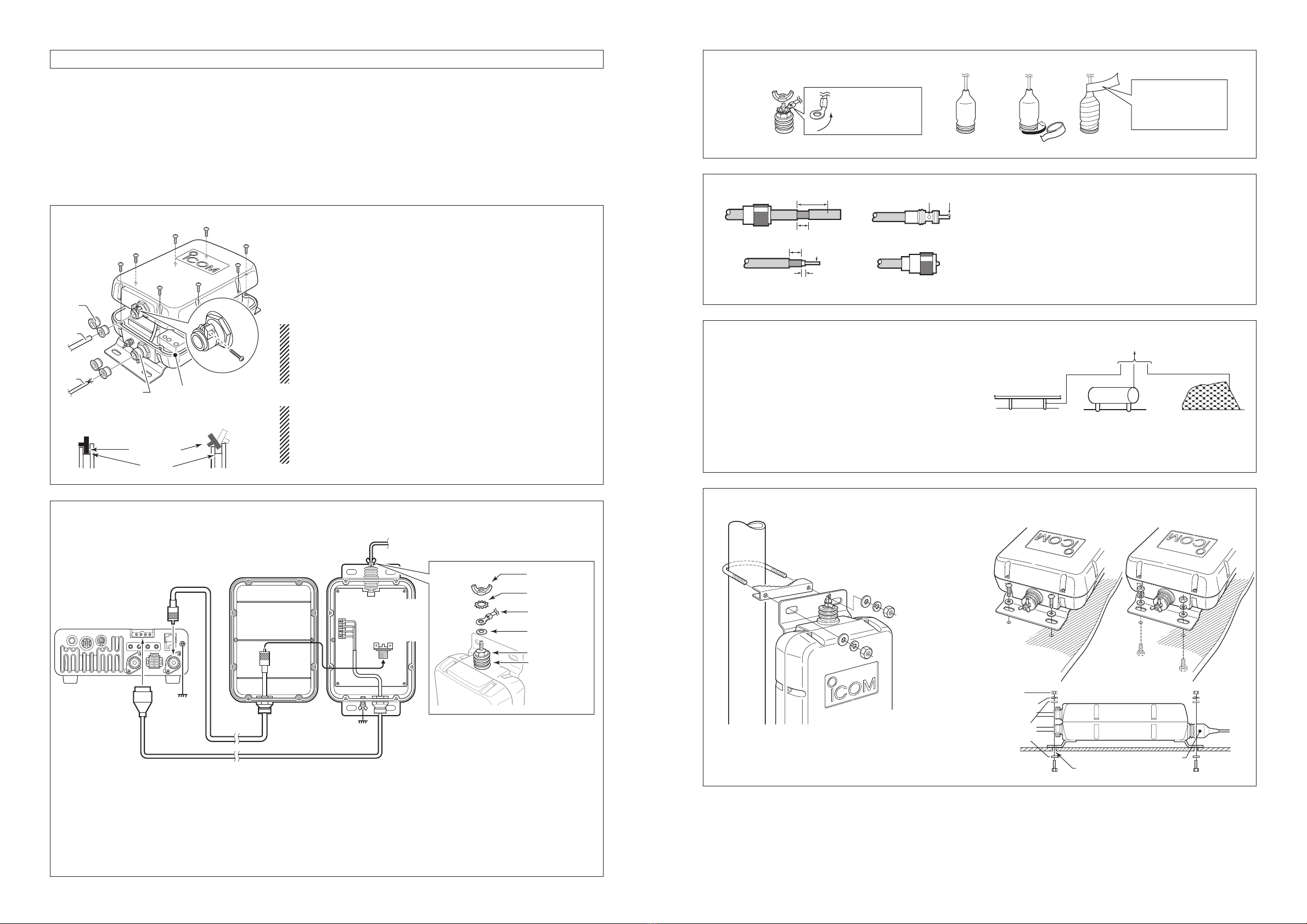
U-boltsq………………………………………………………2
U-bolt bracketsw……………………………………………2
Flatwashers(M6large)e……………………………………8
Flatwashers(M6small)r……………………………………4
Springwashers(M6)t………………………………………8
Nuts(M6)y……………………………………………………8
Hexheadbolts(M6u×50) …………………………………4
Self-tappingscrews(A06i×30) …………………………4
PL-259 connectorso…………………………………………2
!0Weatherproofcap …………………………………………1
!1Rubbervulcanizingtape …………………………………1
Controlcable*(5m;16.4ft) …………………………………1
Coaxialcable*(5D-2V:5m;16.4ft)…………………………1
*Not shown in the illustration to the left.
INSTRUCTIONS
HF+50MHzAUTOMATICANTENNATUNER
AH-4
Thank you for purchasing the AH-4 HF + 50 MHz AU-
TOMATIC ANTENNA TUNER. The AH-4 matches your
transceiver to an antenna more than 7 m/23 ft long (3.5–
54MHz),ortheoptionalAH-2b(7–54MHz).
Please read these instructions thoroughly before installing
and operating the AH-4.
RNEVER operate this tuner without a solid ground. Always
connect the ground wire to the ground terminal. DO NOT use
the mounting plate as a ground terminal.
NEVERtransmitortunewithoutanantennaconnected.Fail-
ure to use an antenna will damage the tuner.
RHIGH VOLTAGE! NEVER touch the antenna while trans-
mitting or tuning. Place the antenna in a position where you
are sure it will not be touched.
DANGER!
WIDE TUNING RANGE❍
TheAH-4providesreliablematchingfrom3.5MHzto54MHz
whenusingatleasta7m(23ft)antenna;or7MHzto54MHz
when using the AH-2b a n t e n n a e l e m e n t .
AUTOMATIC DIGITAL CONTROL TUNING❍
Thebuilt-in8-bitmicroprocessorchoosesthelowestSWRusing
more than 1,040,000 different LC (coil/capacitor) combinations.
45 FREQUENCY MEMORIES FOR FAST TUNING❍
The LC combinations of 45 previously-used frequencies are auto-
maticallymemorized.Onceafrequencyismemorized,theAH-4
tunes on that frequency in less than 1 second. Note that the AH-4
doesnotmemorizeafrequencywhichisnormallytunedwithin2.5
seconds.Memoriesareretainedonlywhenthepowerison.
WEATHERPROOF DESIGN❍
The AH-4’s tightly sealed plastic case allows convenient mount-
ing virtually anywhere. The AH-4 can be mounted outdoors under
your antenna.
0.3 W RADIATED POWER❍
Radiatedpowerduringtuningislessthan0.3W,minimizinginter-
ference to other stations.
✍NOTE:
TheAH-4canbeusedwithmostofIcomHFtransceiver,
whichcoversHFthrough50MHzbands.
However,theIC-706andIC-736canonlybetunedinthe
3.5–30MHzrange.
FEATURES
SUPPLIED ACCESSORIES
Ground terminal
Mounting plate
q
w
e
r
t
y
u
i
o!0
!1
CALCULATION OF UNDESIRABLE ANTENNA LENGTHS
Length of
half wave (½ λ)=300 ×1
Operatingfrequency(MHz) 2
[EXAMPLE]Antenna lengths toavoidwhenoperating at 29.00
MHz
Multiple
of ½ λ=300 ×1×(1, 2, 3…) = 5.2, 10.3, 15.5 m
29 2
Fig.6 MOUNTING EXAMPLES
AH-2b+longwire
AH-2b
a n t e n n a e l e m e n t k i t (op-
tional)
Long wire
Long wire

✍NOTE:Afterinsertingthecoaxialcablethroughthewater-
proof cap and into the AH-4 top cover, solder the PL-259
connectortothecoaxialcable.
Removethetopcover(Fig.1).q
Installthecontrolcableandcoaxialcable(Fig.1).w
ConnectandsolderthePL-259connectortothecoaxiale
cable(Fig.3).
ConnectthecontrolcabletotheAH-4(Fig.2-1).r
ConnecttheGNDcabletotheAH-4(Fig.4).t
Replace the top cover.y
Mount the AH-4 in the desired location; on an antennau
pole,inyourvehicle’strunk,andsoon.(Fig.5).
ConnectanantennatotheAH-4(Fig.6).i
Connect the control cable and the coaxial cable to theo
transceiver.
INSTALLATION
Fig. 2-1 CABLE CONNECTIONS (eg. IC-7000)
Fig. 3 PL-259 CONNECTOR SOLDERING
30 mm
10 mm (Tin)
10 mm
1–2 mm
solder solder
Tin
Coupling ring
qe
r
w
(10 mm ≈3⁄8 in)
Slidethecouplingringoverthecoaxialcable.Carefullyq
cut only the cable jacket, and pull it out to reveal 10 mm
(0.4 in) of braid.
•Tintheexposedbraidandthenpullthejacketout.
Strip the cable, as shown to the left. Tin the entire lengthw
oftheexposedcenterconductor.
Slide the connector body over the cable and solder, ase
shown to the left.
Screw the coupling ring onto the connector body.r
Fig. 5 MOUNTING THE AH-4
• Mounting on an antenna pole
• Mounting on a flat location
Using self-tapping screws Using nuts and bolts
Nut AH-4
Spring
washer
Flat
washer
Hex head
bolt Drill a hole here
(diameter: 6.6–7 mm; 1⁄4–9⁄32 inches)
Weatherproof cap
Using the supplied U-bolts
Fig. 1 COVER REMOVAL AND CABLE INSTALLATION
About the rubber seal
Remove the 8 screws from the top cover and remove the cover.q
Loosen the screws on both cable clamps. If desired, install a strain reliefw
insert (supplied) corresponding to the diameter of the cable.
Installthecoaxialcablethroughthetopcovercableclamp.e
Insert the control cable through the bottom cover cable clamp.r
Afterconnectingthecoaxialcableandcontrolcables,tightenthecablet
clamp screws.
NOTE:
•Makesurethecableclampsarewelltightenedwiththescrews,oth-
erwise the waterproof protection may not be guaranteed.
•Werecommendthatyoualsowraprubbervulcanizingtapeorelectri-
cal tape over the cable clamps for better waterproofing.
NOTE:
Whenattachingthetunercover,makesuredustorothermaterialdoes
not adhere to the rubber seal. If dust or other material is on the seal
when attaching, waterproof protection may not be guaranteed.
Makesuretherubbersealisproperlyseatedintothegroove.
Strain relief
insert
Coaxial
cable
Rubber seal
Control
cable Cable
clamp
Bottom coverBottom cover
Rubber seal
Groove
Correct position Incorrect position
Wing nut
Star washer
Crimp-on wire
terminal
Flat washer
Base nut
Insulator
Coaxial cable
IC-7000 rear panel
Control cable
Bottom
cover
GND
Top cover
PL-259
connector
Antenna element
AH-2b (optional)
J8
J2
Black (GND)
Red (DC13V)
White (START)
Green (KEY)
GND
+See the Fig. 2-2 as shown to the right above.
Put the flat washer, crimp-on wire terminal, star washerq
and then wing nut on the base bolt. Then, tighten the
wing nut.
•Beforeyoutightenthewingnut,makesurethebasenutis
firmly tightened.
•Afteryoutightenthewingnut,carefullybendthewireterminal
up so the wire lines up with the insulator.
Place the weatherproof cap over as much of the insulatorw
as possible.
Wraptheinsulatorwiththerubbervulcanizingtape,start-e
ing at its bottom, then the cap, and finally the antenna
wire.
This will help prevent water seepage.
•Also,youmaywrapelectricaltapeoverthewrappedrubber
vulcanizingtapeforbetterwaterproofing.
Fig. 2-2 Waterproofing the antenna connection
Carefully bend this
part up, AFTER
you tighten the
wing nut.
Pull the tape to slightly
stretch it as you wrap
firmly around the
weatherproof cap.
Rubber vulcanizing tape
q w e
Insulator
Fig. 4 GROUND CONNECTIONS
The transceiver and antenna tuner must have an adequate
ground connection. Otherwise, the overall efficiency of the
transceiver and antenna tuner installation will be reduced.
Interference,RFfeedbackandelectricalshocksfromother
equipment could also occur.
Forbestresults,usetheheaviestgaugewireorstrapavail-
able, and make the connection as short as possible. (see
the illustration to the right)
•AlongwireconnectedtotheGNDterminalasacounterpoiseis
also acceptable.
Copper pipe Metal object Copper screen
To the AH-4 GND terminal
✍NOTE:Connectthecoaxialcabletotheappropriateantenna
connector if the transceiver has more than one.
See your transceiver’s instruction manual for details.
Other manuals for AH-4
5
Table of contents
Other Icom Antenna manuals
Popular Antenna manuals by other brands

Orbit
Orbit OceanTRx manual

Maxview
Maxview MNISAT MXL001 Installation & user's instructions

Sirio Antenne
Sirio Antenne IN-GLASS LTE & WLAN installation manual

Ubiquiti
Ubiquiti AG-HP-2G20 quick start guide

Feig Electronic
Feig Electronic OBID ID ISC.ANT340/240-A Installation

Diamond Antenna
Diamond Antenna SG-M510 manual