manuals.online logo
Brands
  1. Home
  2. •
  3. Brands
  4. •
  5. Icom
  6. •
  7. Antenna
  8. •
  9. Icom AH-8000 User manual

Icom AH-8000 User manual

■はじめに
 このたびは、本製品をお買い上げいただきまして、まことにありが
とうございます。
 本製品は、100MHz ~3300MHzの受信帯域に加え、118MHz、
145MHz、220MHz、430MHz、900MHz、1200MHz、
2400MHzバンドでの送信もできる超広帯域アンテナです。
 設置やご使用の前に、この説明書をよくお読みいただき、本製品の
性能を十分発揮していただくとともに、末長くご愛用くださいますよ
うお願い申し上げます。
■安全上のご注意
1-1-32 Kamiminami, Hirano-ku, Osaka 547-0003, Japan A6664X-1G-2 Printed in Japan
© 2008–2022 Icom Inc.
Icom and the Icom logo are registered trademarks of Icom
Incorporated (Japan) in Japan, the United States, the United
Kingdom, Germany, France, Spain, Russia, Australia, New
Zealand, and/or other countries.
Below statement is for UKCA purpose only
United Kingdom Authorised Importer: Icom (UK) Ltd.
Address: Blacksole House, Altira Park, Herne Bay, Kent, CT6
6GZ, U.K.
【工事について】
設置工事の際、建造物の破損、高所や足場の悪い場所での作業に伴う製品
の落下やけがをしたことによる損害、またはその他のどのような場合にお
いても、当社は一切の責任を負いませんので、あらかじめご了承ください。
なお、高所や足場の悪い場所に取り付ける必要のある場合は危険が伴い
ますので、必ず専門業者にご相談ください。
◎送信中は絶対にアンテナに触れないでください。
 また、容易に人が触れる場所には絶対に設置しないでください。
 
送信中のアンテナは高電圧(数kV)になることがあるため、感電、
けが、故障の原因になることがあります。
◎下記の事項を守らないと、けがの原因になります。
 足場の不安定なところで、設置工事をしないでください。
 人の通行をさまたげる場所には、設置しないでください。
◎下記の事項を守らないと、けがや故障の原因になります。
 
強度の不足する場所や不安定な場所には、設置しないでください。
 強度の不足する部材や腐食しやすい部材は、(アンテナマスト
などには)使用しないでください。
◎下記の事項を守らないと、火災、感電、故障の原因になります。
 同軸ケーブルの上に重いものを載せたり、挟んだりしないでく
ださい。
 同軸ケーブルを無理に曲げたり、ねじったり、引っ張ったり、加
熱したりしないでください。
◎送電線や配電線の近くには、設置しないでください。
 本製品のケーブルなどが触れ、ショートや発熱により感電や火災
の原因になります。
◎雷が鳴り出したら、アンテナや同軸ケーブルには、絶対に触れな
いでください。
 感電の原因になります。
R警告
下記の記載事項は、これを無視して誤った取り
扱いをすると「使用者および周囲の人が、死亡
または重傷を負う可能性が想定される内容」を
示しています。
◎ 雷が鳴り出したら、屋外での設置作業をしないでください。
 火災、感電の原因になることがあります。
◎ 落としたり、強い衝撃を与えたりしないでください。
 けが、故障の原因になることがあります。
◎ テレビやラジオの近くで使用しないでください。
 電波障害を与えたり、受けたりする原因になることがあります。
下記の記載事項は、これを無視して誤った取り
扱いをすると「人が傷害を負う可能性が想定さ
れる内容、および物的損害だけの発生が想定さ
れる内容」を示しています。
R注意
AH-8000 INSTRUCTIONS
/ 取扱説明書
アイコム、ICOM、ICOMロゴは、アイコム株式会社の登録商標です。
本書の内容の一部、または全部を無断で複写/転用することは、禁止されて
います。
Sep. 2022
Foreword
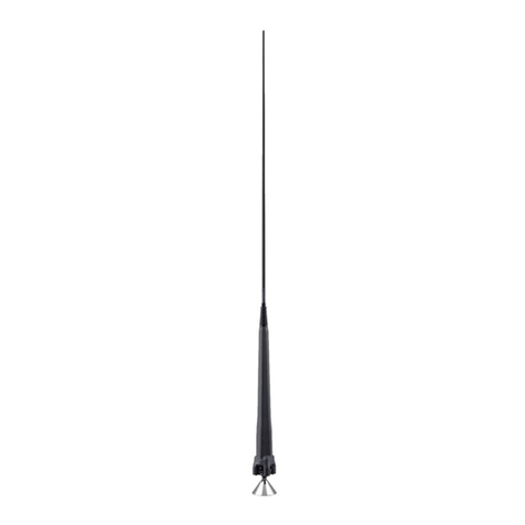
Thank you for purchasing the AH-8000 super wide band
omnidirectional antenna. This antenna covers 100 ~ 3300
MHz for reception and 118, 145, 220, 430, 900, 1200, 2400
MHz bands for transmission.
Please read these instructions thoroughly before using the
AH-8000.
■Precautions
RDANGER! AH-8000 installation is intended for
professional installation only. We are not responsible for
any building breakage, any damage resulting from a drop of
the antenna from a high place or unstable site, or resulting
from any personal injury nor any accident in any other case.
Be sure to consult an expert engineer for installations.
RDANGER HIGH RF VOLTAGE! NEVER touch the
antenna element while transmitting or tuning. This could
cause an electrical shock or burn.
RDANGER HIGH RF VOLTAGE! NEVER install the
antenna at any place that person easily touch the antenna
while transmitting or tuning. This could cause an electrical
shock or burn.
RWARNING! NEVER use the antenna during a lightning
storm. It may result in an electric shock, cause a fire or
damage the antenna. Always disconnect the power source
and antenna before a storm.
RWARNING NEVER assemble or disassemble the
antenna in any crowded area. A person may be injured.
CAUTION: DO NOT use harsh solvents such as Benzine
or alcohol to clean the antenna, as they can damage the
antenna’s surfaces. If the antenna becomes dusty or dirty,
wipe it clean with a dry, soft cloth.
DISCONNECT the antenna when not using the antenna for
a long period of time.
Assembling the antenna/アンテナの組み立て
Supplied items/標準構成品
qAntenna base with bracket pipe ����������1
wDisk elements (long and short) �������� 4 each
eNuts (M4: for disk elements) ������������8
rCone elements (long and short) ������� 4 each
tSet screws��������������������8
yAllen wrench �������������������1
uMounting bracket �������������� 2 sets
iV-bolt sets (including spring washers and nuts) � 2 sets
oScrews (PH M5×15) ���������������2
!0Nuts (M5) ��������������������2
!1Antenna cable with type-N connectors (15 m: 4.9 ft)��1
qアンテナベース(ブラケットパイプ含む) �������� 1個
wディスクエレメント(L、S) ������������� 各4本
eナット(M
4:
ディスクエレメント用) ���������� 8個
rコーンエレメント(L、S) �������������� 各4本
t取り付けネジ(M4×6)���������������� 8個
y六角レンチ ��������������������� 1本
u取り付けブラケット ����������������� 2組
iVボルトセット(Sワッシャ、ナット含む) �������� 2組
oネジ(PHM5×15) ����������������� 2本
!0ナット(M5)��������������������� 2個
!1同軸ケーブル(N型コネクター付き:15m)�������� 1本
547ー0003
大阪市平野区加美南
1ー1ー32
Specifications/電気仕様
wコーンエレメント(L)と(S)をアンテナ
ベースに取り付け、付属の取り付けネ
ジで固定します。
※下図参照
Disk elements (long)
/ディスクエレメント(L)
(340 mm: 133⁄8in)
Disk elements (short)/
ディスクエレメント(S)
(270 mm: 105⁄8in)
Disk element (long)/
ディスクエレメント(L)
Nut/ナット Disk element (short)/
ディスクエレメント(S)
Cone element (short)/
コーンエレメント(S)
(812 mm: 3131⁄32 in)
V-bolts/Vボルト
Mounting bracket/
取り付けブラケット
Nut/
ナット
(M5)
Screw/ネジ(PH M5×15)
Cone element (long)/
コーンエレメント(L)
(1017 mm: 401⁄32 in) 25–50 mm
(1–2 inches)
qRemove 3 screws on the Mounting pipe, and
separate the Antenna base from the pipe. Pass
the antenna cable through the pipe, as shown to
the left, and then connect it to the Antenna base.
wAttach the Cone elements (long and
short) to the Antenna base, and fix the
elements with the Set screwV. See the
illustration below for attaching order.
Antenna base/
アンテナベース
Allen wrench/
六角レンチ
Set screw/
取り付けネジ
eAttach the Disk elements (long and
short) to the Antenna base through
the nuts (M4), and fix the elements
with the nuts. See the illustration
below for attaching order.
rAttach the Mounting bracket to the Mounting pipe,
and then fix it to a pole using the V-bolts.
The pole diameter should be 25 to 50 mm
(1 to 2 inches).
Cone elements (short)/
コーンエレメント(S)
(812 mm: 3131⁄32 in)
Cone element (long)/
コーンエレメント(L)
(1017 mm: 401⁄32 in)
Order of element attachment/
エレメントの取り付け順について
Attach the cone/disk elements in
order, long and short alternately.
コーンおよびディスクエレメントは、
(L)
と(S)が交互に並ぶように取り付
けてください。
q取り付けパイプのネジ
3
本をはずしてアンテナベース
を取りはずします。左図のように、付属の同軸ケーブ
ルを取り付けパイプに通してアンテナベースに取り付
けます。
eディスクエレメント(L)と(S)に付属
のナット(M4)を取り付けてから、ア
ンテナベースに取り付け、ナットで固
定します。
※下図参照
r付属の取り付けブラケットを取り付けパイプに取り付
け、付属のVボルトを使って支柱に固定します。
アンテナを固定する支柱は、直径が
25
mm〜
50
mm
のものをご使用ください。
The Type-N connector can be removed from the
antenna cable if necessary to pass the cable through a
hole for installation.
Be sure to firmly reattach the connector before
connecting it to a transceiver or receiver, and check
that it is not loose.
同軸ケーブルのN型コネクターは、ケーブルを穴に通し
て設置するために、必要に応じてケーブルから取りはず
せます。
無線機/受信機と接続するときは、必ずN型コネクターを
取り付け、ゆるんでいないことを確認してください。
Ty pe-N connector/
N型コネクター
Antenna cable/
同軸ケーブル
• Frequency coverage (Unit: MHz):
RX 100 ~ 3300
TX 118 ~ 137, 144 ~ 148, 222 ~ 225,
430 ~ 450, 902 ~ 928, 1240 ~ 1300,
2300 ~ 2450
• Type of antenna: Omnidirectional Discone antenna
• Gain   : 3 dBi (maximum)
• Antenna connector: Type-N (50 Ω: nominal)
• Maximum input power: 200 W
• Total antenna height: 936 mm (±10 mm): 3 ft (±13⁄32 in)
• Weight (approximate) : 970 g (±20 g): 2 lb 2 oz (±23⁄32 oz)
(except antenna cable)
• Wind resistance : 50 m/sec.: 97.2 kt: 111.8 mph
All stated specifications are subject to change without notice or obligation.
周波数帯域(単位:MHz):
 受信   100~3300
 送信   118~137、144~148、

222~225、430~450、
902~928、1240~1300、
2300~2450
型式  :無指向性ディスコーンアンテナ
アンテナゲイン :3dBi(最大)
アンテナコネクター形状:N型(50Ω)
最大入力電力 :200W(送信可能周波数帯域内に限る)
全高  :936mm(±10mm)
重量  : 約970g(±20g/同軸ケーブル除く)
耐風速 :50m/sec.
※定格、外観、仕様などは、改良のため、予告なく変更することがあります。

Other Icom Antenna manuals

Icom MN-100 User manual

Icom

Icom MN-100 User manual

Icom AL-705 User manual

Icom

Icom AL-705 User manual

Icom AH-4 User manual

Icom

Icom AH-4 User manual

Icom AH-2 User manual

Icom

Icom AH-2 User manual

Icom AH-740 User manual

Icom

Icom AH-740 User manual

Icom AH-703 User manual

Icom

Icom AH-703 User manual

Icom AH-2b User manual

Icom

Icom AH-2b User manual

Icom AH-109PB User manual

Icom

Icom AH-109PB User manual

Icom IC-AH1 User manual

Icom

Icom IC-AH1 User manual

Icom ah-760 User manual

Icom

Icom ah-760 User manual

Icom AH-703 User manual

Icom

Icom AH-703 User manual

Popular Antenna manuals by other brands

Hy-Gain Super Duo-Beam instruction manual

Hy-Gain

Hy-Gain Super Duo-Beam instruction manual

TechniSat DIGIDISH 33 installation manual

TechniSat

TechniSat DIGIDISH 33 installation manual

Queclink GPS MMCX 3M user guide

Queclink

Queclink GPS MMCX 3M user guide

TracStar MVS1200P4 Assembly instructions

TracStar

TracStar MVS1200P4 Assembly instructions

Javad TRIUMPH-1M Plus quick start guide

Javad

Javad TRIUMPH-1M Plus quick start guide

Raymarine STV37 Installation & operation instructions

Raymarine

Raymarine STV37 Installation & operation instructions

Pacific Antenna Dummy Load V2 manual

Pacific Antenna

Pacific Antenna Dummy Load V2 manual

Standard Horizon CP150 Quick reference guide

Standard Horizon

Standard Horizon CP150 Quick reference guide

Ramsey Electronics The `Logi' Log Periodic Antenna LPY915 Assembly and instruction manual

Ramsey Electronics

Ramsey Electronics The `Logi' Log Periodic Antenna LPY915 Assembly and instruction manual

Maco Antennas v-5000 Assembly instructions

Maco Antennas

Maco Antennas v-5000 Assembly instructions

Winsig 3.1 Ultra Operation manual

Winsig

Winsig 3.1 Ultra Operation manual

Poynting OMNI-296 user guide

Poynting

Poynting OMNI-296 user guide

Lorentz ETATRACK active 1500 installation guide

Lorentz

Lorentz ETATRACK active 1500 installation guide

SmartAnt ZYAIR EXT-114 - MOUNTING Assembly guide

SmartAnt

SmartAnt ZYAIR EXT-114 - MOUNTING Assembly guide

ST Engineering Electronics MDM2510 installation guide

ST Engineering Electronics

ST Engineering Electronics MDM2510 installation guide

BAPI BA/ANT418 Installation and operation instructions

BAPI

BAPI BA/ANT418 Installation and operation instructions

Tarheel Antennas 40A-HP instruction manual

Tarheel Antennas

Tarheel Antennas 40A-HP instruction manual

Ubiquiti RD-5G34 installation guide

Ubiquiti

Ubiquiti RD-5G34 installation guide

manuals.online logo
manuals.online logoBrands
  • About & Mission
  • Contact us
  • Privacy Policy
  • Terms and Conditions

Copyright 2025 Manuals.Online. All Rights Reserved.