INSTRUCTIONS
EXTERNAL SPEAKER
SP-34
Thank you for purchasing the SP-34 external
s p e a k e r .
To fully enjoy the benefits of the SP-34, please
read these instructions thoroughly before using the
speaker with a transceiver or receiver.
A-7021X-1G-qa Printed in Japan
© 2012–2016 Icom Inc.
1-1-32 Kamiminami, Hirano-ku, Osaka 547-0003, Japan
The SP-34 EXTERNAL SPEAKER is designed for use
with a wide variety of communication equipment,
especially base station systems. The SP-34 is
equipped with four separate audio network filters
for maximum control of the audio characteristics of
received signals.
FOREWORD
CONNECTIONS
• Instruction manual (This sheet) �������� 1
• Audio cable ����������������� 2
• Feet �������������������� 2
SPECIFICATIONS
• Speaker : 12 cm (4.7 inch) Cone-type
• Rated Input Power : 3 W
• Maximum Input Power : 5 W
• Impedance : 8 Ω
• Frequency Response : 100 to 9000 Hz
• Filter Cut-off frequency :
HPF1 300 Hz at –3 dB point
HPF2 600 Hz at –3 dB point
LPF1 2.4 kHz at –3 dB point
LPF2 800 Hz at –3 dB point
• Filter Response : –6 dB/octave
• Dimentions : 150(H)
× 200(W) × 343(D) mm
(Proj. not included)
5.9(H) × 7.9(W) × 13.5(D) inch
• Weight : Approximately 3 kg (6.6 lbs.)
Icom, Icom Inc. and the Icom logo are registered trademarks of Icom Incorporated (Japan) in Japan, the United
States, the United Kingdom, Germany, France, Spain, Russia and/or other countries.
All stated specifications are subject to change without notice or obligation.
SUPPLIED ACCESSORIES
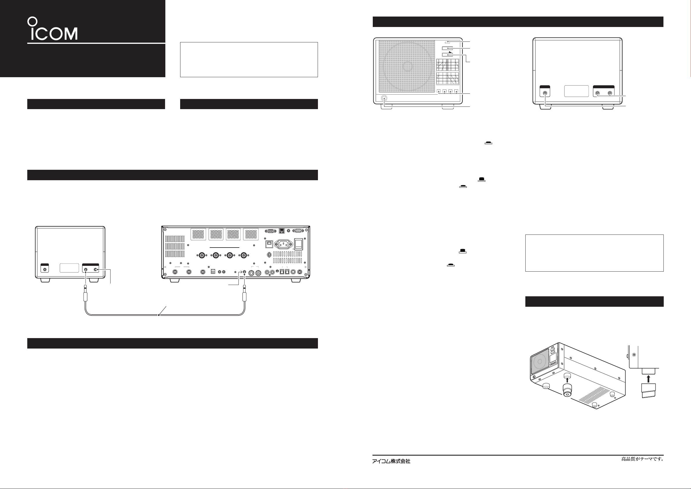
Connect the supplied audio cable between the [INPUT
A] or [INPUT B] jack on the SP-34 rear panel and the
external speaker jack of the transceiver or receiver.
Another jack is available to connect another trans-
ceiver or receiver.
( Audio cable specification: 3.5 (d) mm;1/8” plug, mono-
phonic cable)
SPEAKER OFF
PHONES
HPF1 HPF2LPF1LPF2
INPUT A B
AB
INPUTOUTPUT
FILTER SELECTOR
SWITCHES
SPEAKER
ON/OFF SWITCH
HEADPHONE
JACK
Front panel view Rear panel view
INPUT JACK
SELECTOR
SWITCH
e
w
SPEAKER OFF
LED
q
r
t
INPUT JACKS
OUTPUT JACK
y
u
qSPEAKER OFF LED
When the [SPEAKER OFF] switch is pushed in,
and audio signals are applied to the [INPUT A] or
[INPUT B] jack, the Speaker OFF LED flickers and
varies in intensity relative to the received audio sig-
nal strength.
wSPEAKER ON/OFF SWITCH [SPEAKER OFF]
Push to turn the speaker or headphone audio out-
put ON or OFF.
• Released ( ) : The audio is output.
• Pushed in ( ) : The audio is muted.
Regardless of the [SPEAKER OFF] switch position,
audio signals are output from the [OUTPUT] jack.
NOTE: If no sound is heard from both the speaker
and headphones, make sure the [SPEAKER OFF]
switch is not in the pushed in position.
eINPUT JACK SELECTOR SWITCH [INPUT A/B]
Push to select [INPUT A] or [INPUT B] on the rear
panel.
• Released ( ) : The [INPUT A] jack is selected.
• Pushed in ( ) : The [INPUT B] jack is selected.
r
FILTER SELECTOR SWITCHES
[HPF1], [HPF2], [LPF1], [LPF2]
Push to select the internal audio filters that consist of
high-pass and low-pass filters, with two different cut-off
frequency characteristics for each filter. They are use-
ful in producing a customized, personal audio sound.
•[HPF1]SWITCH
Cuts off audio output frequencies of approximately
300 Hz or less when the switch is pushed in.
•[HPF2]SWITCH
Cuts off audio output frequencies of approximately
600 Hz or less when the switch is pushed in.
•[LPF1]SWITCH
Cuts off audio output frequencies of approximately
2.4 kHz or more when the switch is pushed in.
•[LPF2]SWITCH
Cuts off audio output frequencies of approximately
800 Hz or more when the switch is pushed in.
NOTE: When both the [HPF1] and [HPF2]
switches are pushed in, priority is given to the
[HPF2] switch over the [HPF1] switch. Also in the
[LPF1] and [LPF2] case, priority is given to the
[LPF2] switch over the [LPF1] switch.
tHEADPHONES JACK [PHONES]
Connect a pair of headphones (impedance: 4–16 Ω)
to this jack, if desired. The built-in speaker does not
function while the [PHONES] jack is being used.
yINPUT JACKS [INPUT A], [INPUT B]
Audio signals are applied to [INPUT A] or [INPUT
B]. Use the supplied audio cable to connect be-
tween either jack and the external speaker jack on
your transceiver or receiver. The SP-34 can be con-
nected to two transceivers or receivers using these
jacks.
uOUTPUT JACK [OUTPUT]
This jack outputs audio signals after they pass
through the audio filters specified by the front panel
filter selector switches. This is useful when operat-
ing terminal units such as RTTY, PSK31 or other
data communication modes.
Regardless of the [SPEAKER OFF] switch position,
audio signals are output from this jack.
NOTE: When the [SPEAKER OFF] switch is pushed
in, be sure to turn OFF all of the filters [HPF1],
[HPF2], [LPF1] and [LPF2].
Otherwise the audio signals from the [OUTPUT]
jack might be affected.
PANEL DESCRIPTION
STAND ATTACHMENT
•FRONTPANEL
•REARPANEL
The speaker has adjustable feet for desktop use. Set
the feet to one of two angles, depending on your op-
erating preference.
AB
INPUTOUTPUT
ALC
ADJ
ALCRELAYCW KEY
EXT
KEYPAD
METER
DC OUT
15V
MAX1A
REF I/O
10MHz
-
10dBm
INOUT
REMOTE RS
-
232C
EXT
-
DISPLAY
RX ANT
INOUT
S/P DIF
12
ACC
EXT
-
SP
ANT 1 ANT 2 ANT 3 ANT 4
GND
AC
15A
I
X
-
VERTER
CONNECTION EXAMPLESP-34 (Rear panel) Transceiver or receiver
Supplied audio cable
from another transceiver or receiver
External speaker jack