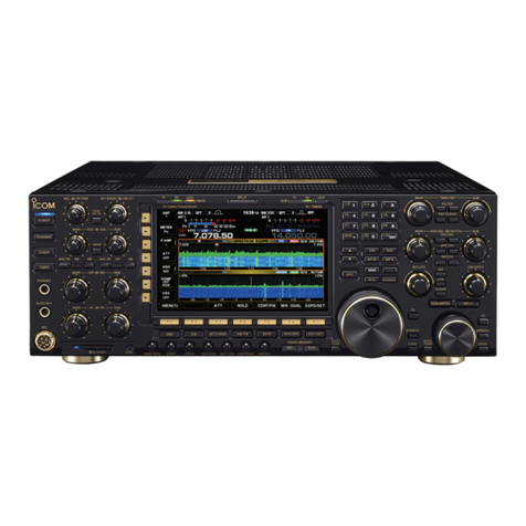
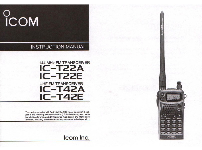
Icom IC-F7000 User manual

HF TRANSCEIVER
iF7000
INSTRUCTION MANUAL

i
FOREWORD
Thank you for purchasing this Icom product. The IC-
F7000
HF TRANSCEIVER
is designed and built with
Icom’s superior technology and craftsmanship. With
proper care, this product should provide you with years
of trouble-free operation.
We want to take a couple of moments of your time to
thank you for making the IC-F7000 your radio of
choice, and hope you agree with Icom’s philosophy of
“technology first.” Many hours of research and devel-
opment went into the design of your IC-F7000.
D
FEATURES
❍ALE (Automatic Link Establishment)/Selcall
capability
❍Digital Signal Processor (DSP) allows flex-
ible filter selection
❍Full-dot matrix LCD for variety of informa-
tion indication
❍PC connection capability for remote control
IMPORTANT
READ THIS INSTRUCTION MANUAL
CAREFULLY before attempting to operate the
transceiver.
SAVE THIS INSTRUCTION MANUAL. This
manual contains important safety and operating in-
structions for the IC-F7000.
EXPLICIT DEFINITIONS
RWARNING RF EXPOSURE! This device
emits Radio Frequency (RF) energy. Extreme caution
should be observed when operating this device. If you
have any questions regarding RF exposure and safety
standards please refer to the Federal Communications
Commission Office of Engineering and Technology’s
report on Evaluating Compliance with FCC Guidelines
for Human Radio Frequency Electromagnetic Fields
(OET Bulletin 65).
RWARNING HIGH VOLTAGE! NEVER at-
tach an antenna or internal antenna connector during
transmission. This may result in an electrical shock or
burn.
RNEVER apply AC to the [DC13.8V] jack on the
transceiver front panel. This could cause a fire or dam-
age the transceiver.
RNEVER apply more than 16 V DC, such as a 24 V
battery, to the [DC13.8V] jack on the transceiver front
panel. This could cause a fire or damage the trans-
ceiver.
RNEVER let metal, wire or other objects touch any
internal part or connectors on the front panel of the
transceiver. This may result in an electric shock.
RNEVER expose the transceiver to rain, snow or
any liquids.
AVOID using or placing the transceiver in areas with
temperatures below –10°C (+14°F) or above +60°C
(+140°F). Be aware that temperatures on a vehicle’s
dashboard can exceed 80°C (+176°F), resulting in per-
manent damage to the transceiver if left there for ex-
tended periods.
AVOID placing the transceiver in excessively dusty en-
vironments or in direct sunlight.
AVOID placing the transceiver against walls or putting
anything on top of the transceiver. This will obstruct
heat dissipation.
Place unit in a secure place to avoid inadvertent use
by children.
During mobile operation, DO NOT operate the trans-
ceiver without running the vehicle’s engine. When the
transceiver’s power is ON and your vehicle’s engine is
OFF, the vehicle’s battery will soon become ex-
hausted.
Make sure the transceiver power is OFF before start-
ing the vehicle. This will avoid possible damage to the
transceiver by ignition voltage spikes.
BE CAREFUL! The rear panel will become hot when
operating the transceiver continuously for long periods.
USE Icom microphones only (supplied or optional).
Other manufacturer’s microphones have different pin
assignments, and connection to the IC-F7000 may
damage the transceiver.
DO NOT use chemical agents such as benzine or al-
cohol when cleaning, as they can damage the trans-
ceiver surface.
PRECAUTION
WORD DEFINITION
RRWARNING Personal injury, fire hazard or electric
shock may occur.
CAUTION Equipment damage may occur.
NOTE If disregarded, inconvenience only. No
risk or personal injury, fire or electric
shock.
Icom, Icom Inc. and the are registered trademarks of
Icom Incorporated (Japan) in the United States, the United
Kingdom, Germany, France, Spain, Russia and/or other
countries.
ii
FOREWORD ……………………………………………i
IMPORTANT …………………………………………… i
EXPLICIT DEFINITIONS …………………………… i
PRECAUTION ………………………………………… i
TABLE OF CONTENTS …………………………… ii
1PANEL DESCRIPTION ………………………… 1–6
■Front panel— Controller ………………………… 1
■Front panel— Main unit ………………………… 3
■Microphone (HM-155) ………………………… 4
■LCD screen ……………………………………… 5
2BASIC OPERATION ………………………… 7–11
■Selecting a channel …………………………… 7
■Scan function …………………………………… 8
■Setting a frequency ……………………………… 9
■Mode selection ………………………………… 10
■Simple mode operation ……………………… 10
■Split frequency operation ……………………… 11
3RECEIVE AND TRANSMIT ………………… 12–18
■Basic voice transmit/receive ………………… 12
■Functions for transmit ………………………… 13
■Functions for receive ………………………… 15
■CW operation …………………………………… 18
■FSK operation ………………………………… 18
4SELCALL/ALE OPERATION ……………… 19–30
■Selcall/ALE ……………………………………… 19
5CHANNEL/ID PROGRAMMING …………… 31–35
■Programming a channel ……………………… 31
■Programming an ID …………………………… 33
6SET MODE …………………………………… 36–53
■Quick set mode ………………………………… 36
■Initial set mode ………………………………… 40
■CPU reset ……………………………………… 53
7CONNECTION AND INSTALLATION …… 54–50
■Supplied accessories ………………………… 54
■Connections ……………………………………55
■Ground connection …………………………… 56
■Power source …………………………………… 56
■Antenna ………………………………………… 57
■Mounting ………………………………………… 58
■Fuse replacement ……………………………… 60
■Connector information ………………………… 61
8SPECIFICATIONS ……………………………… 63
9OPTIONS ………………………………………… 64
TABLE OF CONTENTS
1
2
3
4
5
6
7
8
9
PANEL DESCRIPTION
BASIC OPERATION
RECEIVE AND TRANSMIT
SELCALL /ALE OPERATION
CHANNEL/ID PROGRAMMING
SET MODE
CONNECTION AND INSTALLATION
SPECIFICATIONS
OPTIONS
Versions of the IC-F7000 which display
the “N33” symbol on the serial number
seal, comply with Standard Australia
Specification No. AS/NZS 4770: 2000.

1
1
PANEL DESCRIPTION
■Front panel— Controller
qVOLUME [VOL] (p.12)
Adjusts the audio output level.
wSPEAKER JACK [EXT SP]
Connects the supplied external speaker, SP-25.
eMICROPHONE CONNECTOR [MIC]
Connects the microphone, supplied with the trans-
ceiver.
q+8 V DC output (Max. 10 mA)
wChannel up/down
eMic backlight control line
rPTT
tGND (microphone ground)
yMIC (microphone input)
uGND
iData IN
rPOWER KEY [I/O]
➥While transceiver’s power is OFF:
Push to turn power ON.
•Turn the DC power supply ON in advance.
➥While transceiver’s power is ON:
❍Push momentarily to enter the Quick set mode.
• Push again to exit the Quick set mode.
❍Push for 1 sec. to turn power OFF.
tEMERGENCY KEY [EMG]
➥Push to enter the RFDS channel group.
•Push again to return the normal operating mode.
➥Push for 2 sec. to transmit the RFDS Call.
•1st registered channel is selected automatically when
display is indicated other than the RFDS channel group.
NOTE: The RFDS call is available for AUS version
only. This key is assigned as Emergency Selcall for
other versions. The operation of Emergency Selcall
is same as RFDS call.
yMUTE KEY [MUTE]
Push to select the mute types. Available types are
voice mute, signal level mute (level 1—100), call
mute or mute OFF.
•When select the mute type, transceiver emits different
confirmation beep for each type.
OFF—1 long beep,
Call mute—1 short beep,
Signal level mute—2 short beeps,
Voice mute—3 short beeps
uTUNER KEY [TUNE] (pgs.12, 14)
➥Push for 1 sec. to start manual tune the optional
automatic antenna tuner.
•“Tuning” appears while tuning.
•When the tuner cannot tune the antenna, the tuning
circuit is bypassed automatically after 20 sec.
➥Push momentarily to toggle the optional auto-
matic antenna tuner (AT-140 only) ON and OFF
(bypass).
iSCAN KEY [SCAN]
Push to start and stop the scanning.
oCALL KEY [CALL]
➥Push to enter the Call menu.
• Push again to exit the Call menu.
➥Push for 1 sec. to transmit the Call.
!0 UP/DOWN KEYS [∫∫]/[√√]
Selects the operating channel and the items of the
set mode, etc.
qi
EMG
I/O
TUNE SCAN CALLMUTE
1
QZ 2
ABC 3
DEF
4
GHI 5
JKL 6
MNO
7
PRS 8
TUV 9
WXY
CLR 0
@? OK
HFTRANSCEIVER
VOL
iF7000
r
e
q!0
t
y
u
i
o
Function display Keypad
[VOL]
w[EXT SP]
[MIC]
[I/O]
[EMG]
[MUTE]
[TUNE]
[SCAN]
[CALL]
[UP]/[DN]

2
1
PANEL DESCRIPTION
1
DDKeypad
➥Inputs numeral for the TEL number, ID number,
channel number input, etc.
➥Inputs numeral and alphabet (some symbol) for
the message input of the Page call function or
channel comment input, etc.
1
QZ 2
ABC 3
DEF
4
GHI 5
JKL 6
MNO
7
PRS 8
TUV 9
WXY
CLR 0
@? OK
10-key
[ΩΩCLR]
➥Push momentarily to move the cursor
backward.
➥Push momentarily to decrease the set-
ting value for the set mode.
➥Push momentarily to indicate receive
message when standby condition.
[OK ≈≈]
➥Push to move the cursor forward.
➥Push to increase the setting value for
the set mode.
➥Push to indicate receive message when
standby condition.
➥Push to fix input of channel comments.
OK
CLR
•Available characters
(space)
KEY COMMENTSCH INPUT INPUT
CH
KEY COMMENTS
1 Q Z q z 6 M N O m n o
2 A B C a b c 7 P R S p r s
3 D E F d e f 8 T U V t u v
4 G H I g h i 9 W X Y w x y
5 J K L j k l 0 - / . ' ( ) * + < = > @
1
QZ
2
ABC
3
DEF
4
GHI
5
JKL
6
MNO
7
PRS
8
TUV
9
WXY
0
@?

3
1PANEL DESCRIPTION
■Front panel— Main unit
qDC POWER SOCKET
Accepts 13.8 V DC through the supplied DC power
cable.
wANTENNA CONNECTOR
Connects a 50 ΩHF band antenna via a 50 Ω
matched coaxial cable with a PL-259 plug for both
transmit and receive operation.
eGPS CONNECTOR [GPS]
Input position and UTC data (NMEA0183 ver. 2.0 or
3.01 format), such as from a GPS receiver for set-
ting your positioning and time data automatically.
rREMOTE CONNECTOR [REMOTE]
Connects to a PC via an RS-232C cable (D-sub 9-
pin) for remote control in the NMEA or RS-232C for-
mat.
tREFERENCE CONNECTOR [REF IN]
Connects to an external frequency oscillator for ref-
erence. Ask your technical dealer for details.
yMODEM CONNECTOR [AF/MOD]
Connects to an e-mail modem, NBDP (Narrow
Band Direct Printing) or FAX system.
uACCESSORY CONNECTOR [ACC]
Connects a CW keyer or an FSK terminal unit, etc.
iCONTROLLER CONNECTOR [CONTROLLER]
Connects the supplied remote controller, RC-26.
oSPEAKER JACK [EXT SP]
Connects the supplied external speaker, SP-25.
!0 TUNER CONTROL SOCKET
Connects a control cable to an optional antenna
tuner.
Afemale connector kit is supplied for external an-
tenna tuner connection.
!1
GROUND TERMINAL
IMPORTANT! Connects a ground.
CONTROLLER
ACC
TUNER
GND EXT SP
DC 13.8V
ANT
GPS
REMOTE
REF IN
AF/MOD
q
w
e t
r y
u
i
o
!1
!0

4
1
PANEL DESCRIPTION
■Microphone (HM-155)
qPTT SWITCH [PTT]
Push and hold to transmit; release to receive.
wUP/DOWN SWITCHES [UUPP]/[DDNN]
Push either switch to change the operating channel,
frequency, etc.
eUP/DOWN LOCK SWITCH
Slide to toggle [UP]/[DN] switches function ON and
OFF.
DDKeypad
[1100--kkeeyy]
➥Inputs numeral for the TEL number, ID number,
channel number input, etc.
➥Inputs numeral and alphabet (some symbol) for
the message input of the Page call function or
channel comment input, etc.
• Available characters are shown at page 2.
[ΩΩCLR]
➥Push momentarily to move the cursor
backward.
➥Push momentarily to decrease the set-
ting value for the set mode.
➥Push momentarily to indicate receive
message when standby condition.
[OK ≈≈]
➥Push to move the cursor forward.
➥Push to increase the setting value for
the set mode.
➥Push to indicate receive message when
standby condition.
➥Push to fix input of channel comments.
[TUNE]
➥Push for 1 sec. to start manual tune the
optional antenna tuner.
•“Tuning” appears while tuning.
•When the tuner cannot tune the antenna,
the tuning circuit is bypassed automatically
after 20 sec.
➥Push momentarily to toggle the optional
automatic antenna tuner (AT-140 only)
ON and OFF (bypass).
[SCAN]
➥Push to start and stop the scanning.
[MUTE]
➥Push to select the mute types. Available
types are voice mute, signal level mute
(level 1—100), call mute or mute OFF.
•When select the mute type, transceiver
emits different conformation beep for each
type.
OFF—1 long beep,
Call mute—1 short beep,
Signal level mute—2 short beeps,
Voice mute—3 short beeps
[CALL]
➥Push to enter the Call menu.
• Push again to exit the Call menu.
➥Push for 1 sec. to transmit the Call.
CALL
MUTE
SCAN
TUNE
OK
CLR
21 3
54 6
TUNE
SCAN
mic
87 9
MUTE
0
CALL
CLR OK
q
[PTT]
ON
OFF
e
[LOCK]
w[UP]/[DN]
10-key
1

5
1PANEL DESCRIPTION
DDChannel indication
qCOMMENT INDICATOR
➥Shows the programmed channel comment or
comment with position data when connected GPS
receiver.
➥Shows the condition while scanning/tuning.
•“Scanning” appears when the scan function is ac-
tivated.
•“Tuning” appears while tuning, if an optional exter-
nal antenna tuner is connected. (pgs. 55, 57)
•“Tuned” appears after the tuning is completed.
w
OPERATING MODE INDICATOR
Shows the selected operating mode.
•“USB,” “LSB,” “AM,” “CW,” “FSK,” “AFSK,” “ALE-U,”
“ALE-L” or “EMAIL” appears depending on operating
mode and setting. (Selectable mode is USB only for AUS
version.)
eTRANSMIT/RECEIVE INDICATOR
➥“RX” appears when signals are received or the
squelch is open.
➥“TX” appears during transmit.
rFREQUENCY INDICATOR
Shows the transmit/receive frequency of the chan-
nel. Receive frequency is displayed during recep-
tion, transmit frequency is displayed during trans-
mission. By setting the Initial set mode, both
receive/transmit frequencies can be displayed at
same time. (pgs. 14, 52)
tLQA LEVEL INDICATOR
Shows the LQA level (0–30) for displayed channel
while “ALE-U” or “ALE-L” mode is selected.
•“--”means measurement data is not available.
yS-METER INDICATOR
Shows the receiving signal strength during receive.
uSIMPLE MODE INDICATOR
“-” appears while in simple mode operation.
•While in simple mode operation, Quick set mode, Initial
set mode or etc. cannot be edited.
iTRANSMIT POWER INDICATOR
Shows the selected transmit output power.
•“HI,” “MID,” “LO” appears when the transmit power is
set to high power, middle power, low power respectively.
oMUTE INDICATOR
➥“V” appears when the voice mute is selected.
➥“L” appears when the Signal level mute is se-
lected.
➥“S” appears when the call mute is selected.
!0 CHANNEL NUMBER INDICATOR
➥Shows the selected channel number.
➥Channel number blinks while stopping the scan.
!1 TIME INDICATOR
Shows time data.
ALE-CHANNEL-1
USB-A
LQA:20 ========-------- 12:34
RX-12.163.5
HI
S
-
r
e
w
q
t!1
u
i
o
!0
y
■LCD screen

6
1
PANEL DESCRIPTION
1
DDFrequency indication
q
OPERATING MODE INDICATOR
Shows the selected operating mode.
•“USB,” “LSB,” “AM,” “CW,” “FSK,” “AFSK,” “ALE-U,”
“ALE-L” or “EMAIL” appears depending on operating
mode and setting. (Selectable mode is USB only for AUS
version.)
wTRANSMIT/RECEIVE INDICATOR
➥“RX” appears when signals are received or the
squelch is open.
➥“TX” appears during transmit when the split func-
tion is OFF.
eTRANSMIT/RECEIVE FREQUENCY INDICATOR
Shows the transmit/receive frequency of the chan-
nel. Receive frequency is displayed during recep-
tion, transmit frequency is displayed during trans-
mission when the split function is OFF.
rTRANSMIT INDICATOR
“TX” appears during transmit when the split function
is ON.
tTRANSMIT FREQUENCY INDICATOR
Shows the transmit frequency when the split func-
tion is ON.
yPREAMPLIFIER INDICATOR
“P.AMP” appears when the Preamp function is ON.
uS-METER INDICATOR
Shows the receiving signal strength during receive.
iTRANSMIT POWER INDICATOR
Shows the selected transmit output power.
•“HI,” “MID,” “LO” appears when the transmit power is
set to high power, middle power, low power respectively.
oMUTE INDICATOR
➥“V” appears when the voice mute is selected.
➥“L” appears when the signal level mute is se-
lected.
➥“S” appears when the call mute is selected.
!0 TIME INDICATOR
Shows time data.
ALE-U
RX
P.AMP ========-------- 12:34
TX-12.163.5
HI
S
t
r
e
w
q
y!0
i
o
u

2
7
BASIC OPERATION
■Selecting a channel
The transceiver has 400 regular channels and 100
ALE channels. However, the number of channels can
be restricted in programming depending on your
needs. 2 ways of channel selections are available to
suit your operating style.
DUsing up/down keys
When the display selection is selected the channel in-
dication (see above), push [√√]/[∫∫]on the FRONT
panel or [UP]/[DN] on the microphone to select the
desired channel.
This way is convenient when changing a small num-
ber of channels.
Channel 20
Channel 40
Channel 9980
Push
switch to select
a channel
SELCALL
LSB HI
--0:55
RX 9.900.0
RADTEL
USB HI
--0:55
RX 9.999.9
RADTEL
USB HI
--0:55
RX 0.499.9
[∫]/[√]
[UP]/[DN]
Microphone
or
DDDisplay selection channel/VFO
NOTE: Channel comment (alphanumeric) disap-
pears during Frequency indication. Also Entering
the Initial set mode is restricted.
VFO (FREQUENCY) indicationCHANNEL indication
When or is pushed, the
frequency indication is canceled, and
returns to the channel indication
automatically.
SCAN CALL
USB
RX
12:34
TX-12.163.5
HI
S
ALE-CHANNEL-1
USB-A
12:34
RX-12.163.5
HI
0
@? OK
+

8
2
BASIC OPERATION
2
DUsing the keypad
Enter the number of the desired channel number
using the keypad (0 to 9), then push [OK ≈≈]on the
FRONT panel or microphone.
This way is convenient for remembering the usage
and stored channel number, or when changing large a
number of channels.
•Pushing [ΩΩCLR] clears input digits and retrieves the chan-
nel.
[EXAMPLE]: Selecting channel 20
Push
Push
Push
Blinks
2
ABC
0
@?
OK
RADTEL
USB HI
--0:55
RX 0.499.9
SELCALL
LSB HI
--0:55
RX 8.800.0
SELCALL
LSB HI
--0:55
RX 8.800.0
Blinks
Microphone
[OK ≈]
[10-key]
or
[OK ≈]
[10-key]
Scan function repeatedly scans programmed chan-
nels. This function is convenient to wait for calls on
multiple channels.
qPush [MUTE] several times to select the voice
mute.
•The mute type indicator “V” appears.
wPush [SCAN] to start the scan.
•The “Scanning” indicator appears.
eWhen a signal is received, channel scan pauses
on that channel.
rPush any key to cancel the scan.
NOTE: The scan resume condition (the action after
signal receiving) can be selected as ‘SCAN RE-
SUME’ in the Initial set mode. (p. 45)
[MUTE][SCAN]
■Scan function

9
2BASIC OPERATION
DUsing up/down keys
When the display selection is selected the frequency
indication (p. 7), push [ΩΩCLR] or [OK ≈≈]to move the
cursor to desired tuning steps, then push [√√]/[∫∫]on
the FRONT panel or [UP]/[DN] on the microphone to
change the frequency.
Push
key to change the
frequency in selected
tuning steps.
Push
key to change the
tuning steps.
or
or
USB HI
RX
P.AMP --0:55
USB HI
RX
P.AMP --0:55
USB HI
RX
P.AMP --0:55
CLR OK
[∫]/[√]
Microphone
or [ΩCLR]/[OK ≈]
[UP]/[DN]
[ΩCLR]/[OK ≈]
DUsing the keypad
Enter the desired frequency using the keypad (0 to 9),
then push [OK ≈≈].
•Pushing [ΩΩCLR] clears input digits and retrieves the chan-
nel.
Push
Push
Push
USB HI
RX
P.AMP --0:55
USB HI
RX
P.AMP --0:55
USB HI
RX
P.AMP --0:55
[EXAMPLE]: Entering 12.3450 MHz
1
QZ
2
ABC 3
DEF
4
GHI 5
JKL
0
@? OK
Microphone
[OK ≈]
[10-key]
or
[OK ≈]
[10-key]
■Setting a frequency

10
2
BASIC OPERATION
2
The following modes are available in the IC-F7000:
USB, LSB, AM, CW, FSK, AFSK, ALE-U, ALE-L and
EMAIL.
qPush [I/O] to enter the Quick set mode.
wPush [√√]/[∫∫]several times to select ‘MODE,’ then
push [ΩΩCLR] or [OK ≈≈]to select the desired
mode.
•The selected mode is indicated in the function display.
NOTE: The selected mode can be used for tempo-
rary operation only. Once changing the channel or
turning OFF the transceiver to return the original
operating mode
NOTE: If you want to change the operating mode
on the channel permanently, refer to channel pro-
gramming. (pgs. 31, 32)
[I/O] [ΩCLR]/[OK ≈]
[∫]/[√]
é-SQL-LV----30
--FILTER----WIDE
--RIT-------0
--MODE------ç-USB----å
--BEEP-LV---5
Q-SET-MODE
--LCD-CONT--ç-7-å
è-RF-GAIN---9
--DIMMER----6>0
--TX-PWR----HI
■Mode selection
While pushing and holding [ΩΩCLR], turn power ON
to turn the Simple mode operation ON.
•“-” appears upper-right corner on the display.
•Repeat above procedure to turn the Simple mode opera-
tion OFF.
NOTE: While in simple operating mode, Quick set
mode, Initial set mode, Frequency indication are re-
stricted.
[I/O] [ΩCLR]
Simple mode indication
-
■Simple mode operation

11
2BASIC OPERATION
Split frequency operation allows you to transmit and
receive on two different frequencies.
qWhile in Frequency indication (p. 7), push [I/O] to
enter the Quick set mode.
wPush [√√]/[∫∫]several times to select ‘SPLIT,’ then
push [ΩΩCLR] or [OK ≈≈]to select the split function
ON.
ePush [OK ≈≈]to select ‘DELTA,’ then push [OK ≈≈]
several times to move the cursor to desired tuning
steps, then push [√√]/[∫∫]to change the frequency.
•After exiting the Quick set mode, the TX frequency is indi-
cated in the function display.
[I/O] [ΩCLR]/[OK ≈]
[∫]/[√]
é-RIT-------0
--SPLIT-----ç-DELTA-å
------------0.000.0
--BEEP-LV---5
é-RIT-------0
--SPLIT-----ç-ON-å
--BEEP-LV---5
Q-SET-MODE(VFO)
--MODE------ç-USB----å
è-RF-GAIN---9
--SQL-LV----30
--PRE-AMP---ON
■Split frequency operation

3
12
RECEIVE AND TRANSMIT
2
3
■Basic voice transmit/receive
qCheck the following in advance.
➥Microphone is connected.
➥No mute indication “S,” “L” or “V.”
•If one of “S,” “L” or “V” appears, push [MUTE] sev-
eral times to turn the mute OFF.
w
Selects the desired channel to be received with the
[√√]/[∫∫]or 10-key pad.
•
The S-meter shows signal strength when signal is received.
eAdjust [VOL] to the desired audio level when re-
ceiving a signal.
•If no audio appears, verify ‘SP OUT’ in the Quick set
mode is set to ‘ON.’ (see right)
• If the bass or treble of the receive audio is too strong,
select ‘RIT’ in the Quick set mode and adjust to obtain
clear audio. (see right)
• If Audio is distorted, select ‘MODE’ in the Quick set
mode and set the desired operating mode. (See right)
rPush [TUNE] to tune the antenna tuner ON, if con-
nected.
•“Tuning” indicator appears during the first tun-
ing on a channel.
tTo transmit on the channel, push and hold [PTT] on
the microphone, and speak into the microphone at
a normal voice level.
•The RF meter shows the output power according to your
voice level.
yRelease [PTT] to return to receive.
• Entering the Quick set Mode
qWhile transceiver’s power is ON, push [I/O] mo-
mentarily to enter the Quick set mode, then push
[√√]or [∫∫]to select the item and set the following.
‘SP OUT’
‘RIT’
‘MODE’
wPush [I/O] to exit the Quick set mode.
é-SQL-LV----30
--FILTER----WIDE
--RIT-------0
--MODE------ç-USB----å
--BEEP-LV---5
é-SQL-LV----30
--FILTER----WIDE
--RIT-------ç-0-å
--MODE------USB
--BEEP-LV---5
é-SP-OUT----ç-ON-å
--AGC-------ON
è-NB-LEVEL--9
--MIC-BL----6
--NB--------HI
[I/O] [ΩCLR]/[OK ≈]
[∫]/[√]
[PTT]
Microphone
[TUNE]
[OK ≈]
[10-key][∫]/[√]
[MUTE]
Mute indication
S

■Functions for transmit
ïTransmit power selection
The transceiver has 3 selectable power output levels.
High power allows longer distance communications
and low power reduces power consumption.
qPush [I/O] to enter the Quick set mode while trans-
ceiver’s power is ON.
wPush [∫∫]or [√√]to select ‘TX PWR.’
ePush [ΩΩCLR] or [OK ≈≈]to select the desired out-
put power.
•Output power is selectable in 3 steps (LOW, MID and
HI).
rPush [I/O] to exit the Quick set mode and return to
the normal operating mode.
Q-SET-MODE
--LCD-CONT--ç-6-å
è-RF-GAIN---9
--DIMMER----6
--TX-PWR----HI
[I/O] [ΩCLR]/[OK ≈]
[∫]/[√]
ïMicrophone compressor
IC-F7000 has a built-in, low distortion Mic compres-
sor circuit. This circuit increases your average talk
power in SSB mode and is especially useful when the
receiving station is having difficulty copying your sig-
nal.
qWhile pushing and holding [OK ≈≈], turn power ON
to enter the Initial set mode.
wPush [√√]to select ‘GENERAL,’ then push [OK ≈≈].
ePush [√√]to select ‘COMP,’ then push [ΩΩCLR] or
[OK ≈≈]to turn the mic compressor ON.
rTurn power OFF and ON, then select USB or LSB
mode.
tPush and hold [PTT] on the microphone, and
speak into the microphone at a normal voice level.
GENERAL----
--DISP-TYPE--RX-TX
è-CLOCK------12:00
--COMMENT----ON
--COMP-------ç-ON-å
é-SELCALL----
--ALE--------
è-SCAN-------
--GENERAL----å
--I/O--------
SET-MODE
--CH-LIST----å
è-SCAN-------
--ID-LIST----
--I/O--------
[I/O] [ΩCLR]/[OK ≈]
[∫]/[√]
13
3RECEIVE AND TRANSMIT

14
3
RECEIVE AND TRANSMIT
3
ïTransmit frequency indication
Both receive/transmit frequencies can be displayed at
same time.
qWhile pushing and holding [OK ≈≈], turn power ON
to enter the Initial set mode.
wPush [√√]to select ‘GENERAL,’ then push [OK ≈≈].
ePush [√√]to select ‘DISP TYPE,’ then push
[ΩΩCLR] or [OK ≈≈]to select ‘RX-TX.’
rTurn power OFF and ON.
SELCALL
USB-A
12:34
RX--3.200.0
HI
SELCALL
USB-A
12:34
RX--3.200.0
TX--3.200.0
2020-ch HI TX frequency
indication
• Channel indication
• Frequency indication
GENERAL----
--DISP-TYPE--ç-RX-TX-å
è-CLOCK------12:00
--COMMENT----ON
--COMP-------OFF
[ΩCLR]/[OK ≈][∫]/[√]
é-SELCALL----
--ALE--------
è-SCAN-------
--GENERAL----å
--I/O--------
SET-MODE
--CH-LIST----å
è-SCAN-------
--ID-LIST----
--I/O--------
[I/O] [OK ≈]
■Functions for transmit (Continued)
DDTuner through function
In the combination with IC F7000 and optional AT-
140, the tuner through function can be used.
By bypassing the tuner unit, the receiver gain in par-
ticular frequency band may be improved depending
on your antenna element length.
➥While “TUNE” is displayed, push [TUNE] to tuner
through function ON.
•“TUNE“ disappears.
•Push [TUNE] again to reset the tuner.
[TUNE]

15
3RECEIVE AND TRANSMIT
■Functions for receive
DDRF gain setting
The receiver gain can be reduced with the RF gain
setting. This may help to remove undesired weak sig-
nals while monitoring strong signals.
Usually, the AGC function reduces the RF gain ac-
cording to the receive signal strength and these weak
signals are removed. However, during no signal re-
ception, these weak signals may not be heard.
In such cases, the RF gain may be useful for setting a
minimum level at which to hear signals.
qPush [I/O] to enter the Quick set mode while trans-
ceiver’s power is ON.
wPush [∫∫]or [√√]to select ‘RF GAIN.’
ePush [ΩΩCLR] or [OK ≈≈]to set the desired mini-
mum cutting level.
•
“0” (low sensitivity) to “9” (max. sensitivity) are available.
rPush [I/O] to exit the Quick set mode and return to
the normal operating mode.
Q-SET-MODE
--LCD-CONT--6
è-RF-GAIN---ç-9-å
--DIMMER----6>0
--TX-PWR----HI
[I/O] [ΩCLR]/[OK ≈]
[∫]/[√]
DDSquelch function
The squelch function detects signals with voice com-
ponents and squelches (mutes) unwanted signals
such as unmodulated beat signals. This provides
quiet stand-by.
When you need to receive weak signals, the squelch
should be turned OFF.
➥Push [MUTE] several times to select a mute type.
Available types are voice mute, signal level mute
(level 1—100), call mute or mute OFF.
•When select the mute type, transceiver emits different
confirmation beep for each type.
OFF—1 long beep,
Call mute—1 short beep,
Signal level mute—2 short beeps,
Voice mute—3 short beeps •Mute indication, “S,” “L,” “V” appears when the squelch
function is turned ON.
SELCALL
USB-A
12:34
RX--3.200.0
HI
SMute
indication
[MUTE]

3
16
RECEIVE AND TRANSMIT
3
ïNoise blanker
The noise blanker reduces pulse-type noise such as
that generated by automobile ignition systems.
The noise blanker may distort reception of strong sig-
nals. In such cases, the noise blanker should be
turned OFF.
qPush [I/O] to enter the Quick set mode while trans-
ceiver’s power is ON.
wPush [∫∫]or [√√]to select ‘NB.’
ePush [ΩΩCLR] or [OK ≈≈]to turn the noise blanker
ON.
rPush [∫∫]or [√√]to select ‘NB LEVEL.’
tPush [ΩΩCLR] or [OK ≈≈]to adjust the noise
blanker level.
yPush [I/O] to exit the Quick set mode and return to
the normal operating mode.
When using the noise blanker, received signals
may be distorted if they are excessively strong.
é-SP-OUT----ON
--AGC-------ON
--MIC-BL----OFF
--NB--------ç-ON-å
è-NB-LEVEL--5
[I/O] [ΩCLR]/[OK ≈]
[∫]/[√]
DDAGC OFF function
The receive gain is automatically adjusted according
to received signal strength with the AGC (Automatic
Gain Control) function to prevent distortion from
strong signals and to obtain a constant output level.
When receiving weak signals with adjacent strong
signals or noise, the AGC function may reduce the
sensitivity. In this situation, the AGC function should
be deactivated.
qPush [I/O] to enter the Quick set mode while trans-
ceiver’s power is ON.
wPush [∫∫]or [√√]to select ‘AGC.’
ePush [ΩΩCLR] or [OK ≈≈]to turn the AGC ON.
rPush [I/O] to exit the Quick set mode and return to
the normal operating mode.
é-SP-OUT----ON
--AGC-------ç-ON-å
--MIC-BL----OFF
--NB--------ON
è-NB-LEVEL--5
[I/O] [ΩCLR]/[OK ≈]
[∫]/[√]
■Functions for receive (Continued)

ïPreamp
The preamp amplifies received signals in the front
end circuit to improve the S/N ratio and sensitivity.
Turn this function ON when receiving weak signals.
• Channel indication (p. 7)
qWhile pushing and holding [OK ≈≈], turn power ON
to enter the Initial set mode.
wPush [√√]to select ‘GENERAL,’ then push [OK ≈≈].
ePush [√√]to select ‘PRE AMP,’ then push [ΩΩCLR]
or [OK ≈≈]to turn the preamp function ON.
rTurn power OFF and ON.
• Frequency indication (p. 7)
qPush [I/O] to enter the Quick set mode while trans-
ceiver’s power is ON.
wPush [√√]to select ‘PRE AMP,’ then push [ΩΩCLR]
or [OK ≈≈]to turn the preamp function ON.
ePush [I/O] to exit the Quick set mode and return to
the normal operating mode.
Q-SET-MODE(VFO)
--MODE------USB
è-RF-GAIN---9
--SQL-LV----30
--PRE-AMP---ç-ON-å
Q-SET-MODE(VFO)
--MODE------ç-USB----å
è-RF-GAIN---9
--SQL-LV----30
--PRE-AMP---ON
[I/O] [ΩCLR]/[OK ≈]
[∫]/[√]
é-PASSWORD---LOCK
--PRE-AMP----ç-ON-å
è-CLOCK------12:00
--VOL-MIN----0
--COMP-------ç-ON-å
é-SELCALL----
--ALE--------
è-SCAN-------
--GENERAL----å
--I/O--------
SET-MODE
--CH-LIST----å
è-SCAN-------
--ID-LIST----
--I/O--------
■Functions for receive (Continued)
17
3RECEIVE AND TRANSMIT
ïRIT function
The RIT (Receive Incremental Tuning) function com-
pensates for off-frequencies of communicating sta-
tions. The function shifts the receive frequency up to
±150 Hz without moving the transmit frequency.
qPush [I/O] to enter the Quick set mode while trans-
ceiver’s power is ON.
wPush [∫∫]or [√√]to select ‘RIT.’
ePush [ΩΩCLR] or [OK ≈≈]to tune the frequency.
•The transmit frequencies are not shifted.
rPush [I/O] to exit the Quick set mode and return to
the normal operating mode.
When cancelling the RIT function, tune the ‘RIT’ in
the Quick set mode to ‘0.’
é-SQL-LV----30
--FILTER----WIDE
--RIT-------ç-0-å
--MODE------USB
--BEEP-LV---5
[I/O] [ΩCLR]/[OK ≈]
[∫]/[√]
Other manuals for IC-F7000
2
Table of contents
Other Icom Transceiver manuals

Icom
Icom IC-M700TY User manual

Icom
Icom IC-F6220D User manual

Icom
Icom IC-4SAT User manual

Icom
Icom IC-V82 User manual

Icom
Icom IC-F4160 SERIES User manual

Icom
Icom IC-04A User manual

Icom
Icom IC-F70DT User manual

Icom
Icom D-STAR ID-4100A User manual

Icom
Icom IC-M88 User manual

Icom
Icom IC-F5220D User manual
Popular Transceiver manuals by other brands

Delta Electronics
Delta Electronics SFBD-1250B4Q1R Specifications

Sporty's
Sporty's SP-200 Operator's manual

Kenwood
Kenwood TS-830S Service manual

Becker
Becker AR620X Installation and operation

Technisonic Industries Limited
Technisonic Industries Limited T3018 user guide

Palomar
Palomar SSB-500 instruction manual