Icom IC-M803 User manual

This device complies with Part 15 of the FCC rules. Operation is
subject to the following two conditions: (1) This device may not cause
harmful interference, and (2) this device must accept any interference
received, including interference that may cause undesired operation.
INSTRUCTION MANUAL
|M803
MF/HF MARINE TRANSCEIVER

i
Thank you for choosing this Icom product. This
product is designed and built with Icom’s state of the
art technology and craftsmanship. With proper care,
this product should provide you with years of trouble-
free operation.
IMPORTANT
READ ALL INSTRUCTIONS carefully completely
before using the transceiver.
SAVE THIS INSTRUCTION MANUAL— This
instruction manual contains important operating
instructions for the IC-M803.
This instruction manual includes some functions that
are usable only when your dealer preset them.
Ask your dealer for details.
EXPLICIT DEFINITIONS
WORD DEFINITION
RDANGER! Personal death, serious injury, or an
explosion may occur.
RWARNING!
shock may occur.
CAUTION Equipment damage may occur.
NOTE
If disregarded, inconvenience only.
electric shock.
Icom is not responsible for the destruction, damage
to, or performance of any Icom or Non-Icom
equipment, if the malfunction is because of:
•
natural disasters, disturbances, riots, war, or
radioactive contamination.
• The use of Icom transceivers with any equipment
that is not manufactured or approved by Icom.
IN CASE OF EMERGENCY
If your vessel requires assistance, contact other vessels
and the Coast Guard by sending a distress call using DSC
(digital selective calling) on an emergency frequency.
When immediate help is needed:
1. Lift the key cover, hold down [DISTRESS] for 3
seconds until the 3 short beeps and then one
long beep sound.
2. Wait for an acknowledgment from another station.
3. After the acknowledgment is received, hold
down [PTT] on the microphone and send the
following information.
1“MAYDAY, MAYDAY, MAYDAY.”
2“THIS IS . . . . . . . . (name of the vessel).”
3“LOCATED AT . . . .(vessel’s position).”
4Give the reason for the distress call.
5Explain what assistance you need.
6Give additional information about your vessel:
• Type
• Length
• Color
• The number of people on board
FEATURES
zMeets the latest ITU-R M.493-13 DSC
zIPX7 water proof construction (remote controller only)
zEasy user interface
The remote controller has the 4.3 inches wide
viewing angle, and the color display with Day and
Night modes.
zAutomatic Voice Recording function
Records the last 120 seconds (max.) of receiving
audio.
zIndependent Emergency channels
Monitor Distress voice frequencies.
zBuilt-in Class E DSC function
The transceiver has the DSC functions for distress
alert transmission and reception, as well as the
general DSC calls such as Individual calls, Group
calls, and so on.
zBuilt-in GPS receiver
zNMEA 0183 (4800 to 38400 bps) available
zAT-130/AT-140 optional antenna tuner
z150 W of powerful output power
zRF Direct Sampling system employed
Icom, Icom Inc. and the Icom logo are registered
trademarks of Icom Incorporated (Japan) in Japan,
the United States, the United Kingdom, Germany,
France, Spain, Russia, Australia, New Zealand, and/or
other countries.

ii
RADIO OPERATION WARNING
WARNIN G
Icom requires the radio operator to meet
the FCC Requirements for Radio
Frequency Exposure. An omnidirectional
antenna with gain not greater than 9 dBi
must be mounted a minimum of 5 meters
(measured from the lowest point of the antenna)
vertically above the main deck and all possible
personnel. This is the minimum safe separation
distance estimated to meet all RF exposure
compliance requirements. This 5 meter distance is
based on the FCC Safe Maximum Permissible
Exposure (MPE) distance of 3 meters added to the
height of an adult (2 meters) and is appropriate for all
vessels.
For watercraft without suitable structures, the antenna
must be mounted so as to maintain a minimum of 1
meter vertically between the antenna, (measured from
the lowest point of the antenna), to the heads of all
persons AND all persons must stay outside of the 3
meter MPE radius.
Do not transmit with radio and antenna when persons
are within the MPE radius of the antenna, unless
such persons (such as driver or radio operator) are
barrier. The MPE Radius is the minimum distance
from the antenna axis that person should maintain in
order to avoid RF exposure higher than the allowable
MPE level set by FCC.
FAILURE TO OBSERVE THESE LIMITS MAY
ALLOW THOSE WITHIN THE MPE RADIUS TO
EXPERIENCE RF RADIATION ABSORPTION
WHICH EXCEEDS THE FCC MAXIMUM
PERMISSIBLE EXPOSURE (MPE) LIMIT.
IT IS THE RESPONSIBILITY OF THE RADIO
OPERATOR TO ENSURE THAT THE MAXIMUM
PERMISSIBLE EXPOSURE LIMITS ARE
OBSERVED AT ALL TIMES DURING RADIO
TRANSMISSION. THE RADIO OPERATOR IS TO
ENSURE THAT NO BYSTANDERS COME WITHIN
THE RADIUS OF THE MAXIMUM PERMISSIBLE
EXPOSURE LIMITS.
Determining MPE Radius
THE MAXIMUM PERMISSIBLE EXPOSURE (MPE)
RADIUS HAS BEEN ESTIMATED TO BE A RADIUS
OF ABOUT 3M PER OET BULLETIN 65 OF THE
FCC.
THIS ESTIMATE IS MADE ASSUMING THE
MAXIMUM POWER OF THE RADIO AND
ANTENNAS WITH A MAXIMUM GAIN OF 9dBi ARE
USED FOR A SHIP MOUNTED SYSTEM.
AVERTISSEMENT POUR LES
OPÉRATEURS RADIO
AVERTISSEMENT
Icom exige que l’opérateur radio se conforme
aux exigences de la FCC en matière
d’exposition aux radiofréquences. Une
antenne omnidirectionnelle dont le gain ne
distance minimale de 5 mètres (mesurée depuis le point le
plus bas de l’antenne) verticalement au-dessus du pont
principal et de tout le personnel qui peut s’y trouver. Il s’agit
de la distance de sécurité minimale prévue pour satisfaire
aux exigences de conformité en matière d’exposition aux RF.
Cette distance de 5 mètres est établie en fonction de
l’exposition maximale admissible sécuritaire de 3 mètres
(2 mètres); cette distance convient pour tous les navires.
Dans le cas des embarcations sans structure convenable,
minimale de 1 mètre verticalement entre cette antenne
(mesurée depuis son point le plus bas) et la tête de toute
personne présente; toutes les personnes présentes doivent
admissible de 3 mètres.
personnes (comme le conducteur ou l’opérateur radio)
ne soient protégées du champ de l’antenne par un écran
personne doit maintenir entre elle et l’axe de l’antenne
pour éviter une exposition aux RF supérieure au niveau
LE NON-RESPECT DE CES LIMITES PEUT CAUSER,
POUR LES PERSONNES SITUÉES DANS LE RAYON
D’EXPOSITION MAXIMALE ADMISSIBLE, UNE ABSORPTION
DE RAYONNEMENT DE RF SUPÉRIEURE À L’EXPOSITION
MAXIMALE ADMISSIBLE FIXÉE PAR LA FCC.
L’OPÉRATEUR RADIO EST RESPONSABLE D’ASSURER
QUE LES LIMITES D’EXPOSITION MAXIMALE
ADMISSIBLE SOIENT RESPECTÉES EN TOUT TEMPS
PENDANT LA TRANSMISSION RADIO. L’OPÉRATEUR
RADIO DOIT S’ASSURER QU’AUCUNE PERSONNE
PRÉSENTE NE SE SITUE À L’INTÉRIEUR DU RAYON
D’EXPOSITION MAXIMALE ADMISSIBLE.
Établir le rayon d’exposition maximale admissible
ON ESTIME QUE LE RAYON D’EXPOSITION MAXIMALE
ADMISSIBLE EST D’ENVIRON 3 M, TEL QUE STIPULÉ
DANS LE BULLETIN OET 65 DE LA FCC. CETTE
DISTANCE ESTIMÉE TIENT COMPTE D’UN SYSTÈME
INSTALLÉ SUR UN NAVIRE UTILISANT LA PUISSANCE
MAXIMALE DE LA RADIO ET DES ANTENNES DONT LE
GAIN MAXIMAL EST DE 9dBi.
Determining MPE Radius
THE MAXIMUM PERMISSIBLE EXPOSURE (MPE) RADIUS
HAS BEEN ESTIMATED TO BE A RADIUS OF ABOUT 3M
PER OET BULLETIN 65 OF THE FCC.
THIS ESTIMATE IS MADE ASSUMING THE MAXIMUM
POWER OF THE RADIO AND ANTENNAS WITH A MAXIMUM
GAIN OF 9dBi ARE USED FOR A SHIP MOUNTED SYSTEM.

iii
FCC INFORMATION
This equipment has been tested and found to comply
with the limits for a Class A digital device, pursuant to
part 15 of the FCC Rules. These limits are designed
to provide reasonable protection against harmful
interference when the equipment is operated in a
commercial environment. This equipment generates,
uses, and can radiate radio frequency energy and,
if not installed and used in accordance with the
instruction manual, may cause harmful interference to
radio communications.
Operation of this equipment in a residential area is
likely to cause harmful interference in which case the
user will be required to correct the interference at his
own expense.
CAUTION:
transceiver, not expressly approved by Icom Inc.,
could void your authority to operate this transceiver
under FCC regulations.
INFORMATION FCC
Cet équipement a été testé et reconnu conforme aux
A, conformément au point 15 de la réglementation
une protection raisonnable contre le brouillage
préjudiciable lorsque cet appareil est utilisé dans un
environnement commercial. Cet équipement génère,
utilise et peut émettre un rayonnement de fréquence
radio. S’il n’a pas été installé conformément aux
instructions, il peut par ailleurs créer des interférences
perturbant les communications radio.
résidentielle peut provoquer un brouillage
préjudiciable, auquel cas l’utilisateur sera tenu de
MISE EN GARDE:
non expressément approuvé par Icom Inc., peut

iv
RDANGER HIGH RF VOLTAGE! NEVER touch
an antenna while transmitting. This may result in an
electrical shock or burn.
RWARNING! NEVER operate the transceiver during
a lightning storm. It may result in an electric shock,
disconnect the power source and antenna before a
storm.
RWARNING! NEVER connect the transceiver directly
in an electric shock.
RWARNING! NEVER mount the transceiver’s
main unit overhead. The weight of the main unit is
approximately 4.41 kg (9.7 lb), and it could easily fall
due to wave shocks or vibration. The unit must be
RWARNING! NEVER connect a power source of
more than 16 V DC. This connection could cause a
RWARNING! NEVER reverse the DC power cable
equipment.
RWARNING! NEVER remove the fuse holder on the
DC power cable. Excessive current caused by a short
RWARNING! NEVER place the transceiver where
normal operation of the vessel may be hindered, or
where it could cause bodily injury.
RWARNING! NEVER let metal, wire or other objects
protrude the transceiver or into connectors on the rear
panel. This may result in an electric shock.
CAUTION: DO NOT use harsh solvents such as
damage the transceiver’s surfaces.
CAUTION: DO NOT use the transceiver in areas with
temperatures out of the range of –20°C ~ +55°C
(–4°F ~ +131°F).
CAUTION: DO NOT place the transceiver in
excessively dusty environments or direct sunlight.
CAUTION: DO NOT use non-Icom microphones.
assignments, and connection to the transceiver may
damage the transceiver.
CAUTION: DO NOT place the transceiver against
walls or putting anything on top of the transceiver. This
may overheat the transceiver.
BE CAREFUL! The transceiver’s main unit will
become hot when operating the transceiver
continuously for long periods.
BE CAREFUL! The remote controller’s front panel
meets IPX7 requirements for waterproof protection.
However, once the transceiver has been dropped,
or the waterproof seal is cracked or damaged,
waterproof protection cannot be guaranteed because
of possible damage to the case or the waterproof seal.
LThe connectors on the rear panel do not meet IPX7.
NOTE: The LCD may have cosmetic imperfections
that appear as small dark or light spots. This is not a
malfunction or defect, but a normal characteristic of
LCDs.
NOTE: Install the transceiver and microphone more
than 1 meter (3.3 ft) from the vessel’s magnetic
navigation compass.
NOTE: Always place the unit in a secure place to
PERCAUTIONS

v
RDANGER TENSION À HAUTES RF ! NE JAMAIS
toucher l’antenne pendant une transmission. Cela
risquerait de provoquer un choc électrique ou des
brulures.
RAVERTISSEMENT ! NE JAMAIS utiliser
l’émetteur-récepteur durant un orage. Cela risquerait
de provoquer un choc électrique, un incendie ou
d'endommager l’émetteur-récepteur. Toujours
débrancher la source d'alimentation et l’antenne avant
une tempête.
RAVERTISSEMENT ! NE JAMAIS brancher
directement l’émetteur-récepteur sur une prise de
courant alternatif. Cela pourrait provoquer un choc
électrique ou un incendie.
RAVERTISSEMENT ! NE JAMAIS monter l’unité
principale de l’émetteur-récepteur au-dessus de la tête.
Le poids de l’unité est d'environ 4.41 kg (9.7 lb), et elle
pourrait facilement tomber en raison des vibrations
ou du choc des vagues. L’unité doit uniquement être
montée sur une surface dure et plate.
RAVERTISSEMENT ! NE JAMAIS raccorder une
raccordement pourrait causer un incendie ou détruire
l'émetteur-récepteur.
RAVERTISSEMENT ! NE JAMAIS inverser la
polarité du câble d’alimentation CC lors de la
endommager l’émetteur-récepteur.
RAVERTISSEMENT ! NE JAMAIS retirer le porte-
fusible du câble d'alimentation CC. Un courant
excessif provoqué par un court-circuit pourrait causer
un incendie ou endommager l'émetteur-récepteur.
RAVERTISSEMENT ! NE JAMAIS placer jamais
pourrait causer des blessures corporelles.
RAVERTISSEMENT ! NE JAMAIS laisser de métal,
récepteur ou dans les connecteurs sur le panneau
arrière. Cela risquerait de provoquer un choc
électrique.
ATTENTION : NE PAS utiliser de dissolvants
nettoyage, car ils endommageraient les surfaces de
l’émetteur-récepteur.
ATTENTION : NE PAS utiliser ou placer l’émetteur-
températures hors de la plage de –20°C ~ +55°C
(–4°F ~ +131°F).
ATTENTION : NE PAS placer l’émetteur-récepteur
dans un environnement excessivement poussiéreux
ou en plein soleil.
ATTENTION : NE PAS utiliser de microphones autres
que Icom. Les microphones des autres fabricants
le raccordement au l’émetteur-récepteur risque
d’endommager l’émetteur-récepteur.
ATTENTION : NE PAS placer l’émetteur-récepteur
contre un mur ou poser des objets dessus. Il risquerait
MISE EN GARDE ! L’unité principale de l’émetteur-
longue durée de l’émetteur-récepteur.
MISE EN GARDE ! Le panneau avant de la
télécommande est conforme aux exigences IPX7
en matière de protection étanche. Cependant, une
fois que l’émetteur-récepteur est tombé, ou que
protection étanche ne peut pas être garantie en
raison des dommages possibles au boitier ou au joint
d’étanchéité.
LLes connecteurs sur le panneau arrière ne sont pas
REMARQUE : L’écran LCD peut avoir des
imperfections cosmétiques qui apparaissent sous
forme de petites taches sombres ou lumineuses. Il ne
s’agit pas un dysfonctionnement ou d'un défaut, mais
d’une caractéristique normale des écrans LCD.
REMARQUE :
route du navire.
REMARQUE :
sûr pour éviter que des personnes non autorisées ne
l’utilisent par inadvertance.
PRÉCAUTIONS

vi
KEY ICON DESCRIPTION
The keys are described in this manual as follows:
The keys that have words or letters on them are
described with the characters “[ ].”
Example: [ENT], [CLR]
The Software Keys are described with the words or
letters on a blue background, such as
or
.
The functions of the keys are shown at the bottom of
the display. Push the key below the desired function.
You can use the following keys on the Menu screen.
FUNCTION ACTION
Select
Enter Push [ENT], [CH/GRP], or
.
Go to the next tree level
or .
Go back to the previous
tree level
.
Cancel Push [CLR].
Exit Push .
The following action icons describe [CH/GRP], [ENT],
zRotate : Rotate [CH/GRP] to select.
zPush : Push [ENT] to enter or set.
zPush : Push the Keypad keys to enter a digit
or text.
zPush
RECOMMENDATION
CLEAN THE REMOTE CONTROLLERʼS
FRONT PANEL THOROUGHLY IN A BOWL OF
FRESHWATER after exposure to saltwater, and dry
keys, switches may become unusable, due to salt
LThe connectors on the rear panel do not meet IPX7
.
NOTE: If the remote controller’s waterproof
protection appears defective, carefully clean it with
a soft, damp (freshwater) cloth, then dry it before
operating. The remote controller may lose its
waterproof protection if the case or connector cover
is cracked or broken, or the remote controller has
been dropped. Contact your Icom distributor or your
dealer for advice.

vii
IMPORTANT..................................... i
EXPLICIT DEFINITIONS.................. i
IN CASE OF EMERGENCY............. i
FEATURES....................................... i
RADIO OPERATION WARNING......ii
AVERTISSEMENT POUR LES
OPÉRATEURS RADIO.....................ii
FCC INFORMATION .......................iii
INFORMATION FCC .......................iii
PERCAUTIONS...............................iv
PRÉCAUTIONS............................... v
KEY ICON DESCRIPTION..............vi
RECOMMENDATION......................vi
1 OPERATING RULES ................ 1
2 PANEL DESCRIPTION............. 2
Main unit front panel ........................2
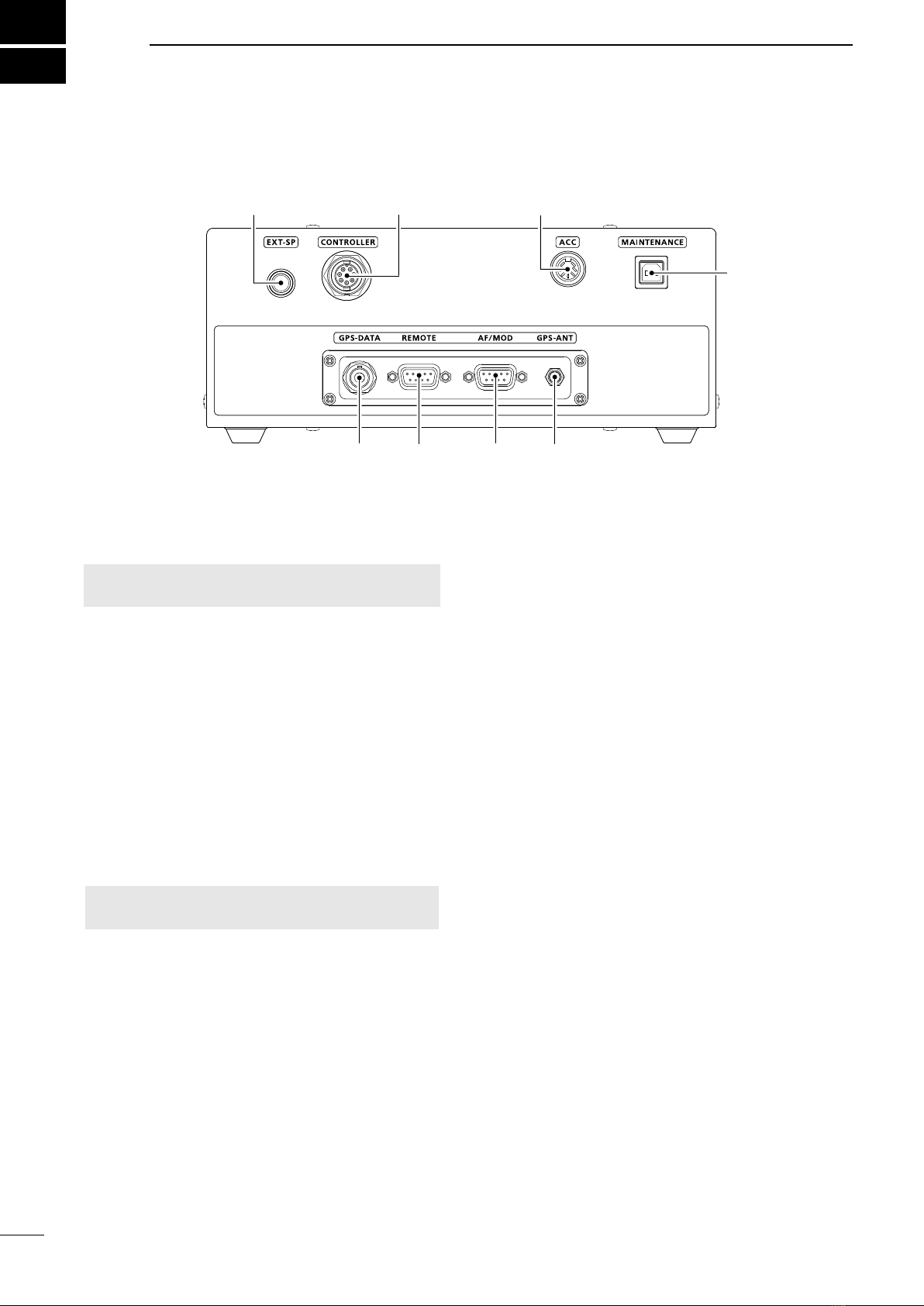
Main unit rear panel.........................3
Remote Controller front panel..........4
Optional HM-214M...........................5
Software Keys..................................5
DSelecting a Software Key function
..5
DFunctions.....................................6
Function display (Main screen)........7
DStatus area..................................7
DTask area.....................................7
DInformation area ..........................7
DChannel area...............................7
DSoftware Key area.......................8
DPosition and Time area ...............8
3 PREPARATION......................... 9
Entering the MMSI code ..................9
4 MENU SCREEN...................... 10
Menu Construction.........................10
Selecting the item .......................... 11
5 BASIC OPERATION ............... 12
Selecting a channel or Group ........12
DUsing the channel and group
selector......................................12
DUsing the Keypad keys .............12
DChannel and Channel Group list
..12
Receiving and transmitting ............13
DReceiving ..................................13
DTransmitting...............................13
DSC Scan......................................13
CW operation.................................14
DConnecting a CW key ...............14
FSK operation................................14
DConnecting an FSK terminal unit
..14
e-mail operation.............................15
DOperation ..................................15
De-mail Filter ...............................15
6 OTHER FUNCTIONS AND
OPERATIONS......................... 16
Backlight function...........................16
Scan...............................................16
DCH and CH Resume .................16
DProgram ....................................17
Using the Voice Recorder..............17
DPlayback the recorded voice.... 17
Other functions ..............................18
Setting a temporary operating
frequency.......................................20
Setting a User channel, an ITU
Simplex channel, or an e-mail
channel ..........................................21
Assigning a function.......................22
DAssigning a Software Key function
to a Software Key
.......................22
DAssigning a Software Key function
to [VOL]
......................................23
DAssigning a Software Key
function to [P] on the HM-214H
.............................23
7 DSC OPERATION................... 24
DSC address ID.............................24
DEntering an Individual or Group ID
..................................................24
DDelete an entered ID .................25
Entering the position data and time
..26
DSC Task mode (Single) ...............27
DSoftware Key functions .............27
DUnread List................................27
DSC Task mode (Multiple).............28
DSoftware Key functions .............28
DTask List ....................................28
Sending DSC calls (Distress) ........29
DSimple call.................................29
DRegular call ...............................30
DResending a Distress call..........31
DDistress Cancel call...................32
DSending a Distress Relay
Acknowledgment.......................34
Sending DSC calls (other) .............35
DSending an Individual call .........35
DSending an Individual
Acknowledgment.......................36
DSending a Group call.................37
DSending a Geographical Area call
..................................................39
DSending a Test call ....................42
DSending a Test call
Acknowledgment.......................43
Receiving DSC calls (Distress)......44
DReceiving a Distress call ...........44
DReceiving a Distress
Acknowledgment.......................45
DReceiving a Distress Cancel call
..45
DReceiving a Distress Relay call
..46
DReceiving a Distress Relay
Acknowledgment.......................47
Receiving DSC calls (other)...........48
DReceiving an Individual call.......48
DReceiving an Individual
Acknowledgment.......................49
DReceiving a Group call ..............50
DReceiving a Geographical Area
call.............................................51
DReceiving a Test call .................52
DReceiving a Test Acknowledgment
..................................................53
DSC Log ........................................54
DReceived DSC Log....................54
DTransmitted DSC Log................54
DSC Settings .................................55
DDSC Frequency.........................55
DScanning Receiver ....................56
DAuto ACK...................................57
DCH Auto Switch .........................58
DNMEA Data Output....................58
DAlarm Status..............................58
DSelf Check Test .........................60
DProcedure..................................60
8 MENU ITEMS.......................... 61
Menu items ....................................61
GPS Information ............................62
.................................62
Radio Settings ...............................65
Radio Information ..........................67
9 CONNECTIONS AND
INSTALLATION....................... 68
Supplied accessories.....................68
Connections...................................68
DConnecting the microphone ......68
DConnecting the remote control
cable..........................................69
DFront panel connections............69
DRear panel connections ............70
Ground connection ........................71
Power source.................................71
Antenna .........................................72
DMN-100/MN-100L
..................................72
DAT-130/AT-120/AH-3
.........................72
DNon-Icom Tuner ........................72
DAT-140
........................................72
Mounting........................................73
DMounting location ......................73
DMounting the remote controller
..73
DMounting the Main unit..............73
MB-75 installation ..........................74
Transceiver dimensions.................75
Fuse replacement..........................76
DCircuitry fuse .............................76
DDC power cable fuses ...............77
Connector information ...................78
10 SPECIFICATIONS AND
OPTIONS ................................ 80
11 TROUBLESHOOTING............ 82
TABLE OF CONTENTS
TEMPLATE ..................................83
INDEX...........................................85

1
1
1
OPERATING RULES
NOTE: Before transmitting, monitor the channel you
want to use to avoid interrupting communications
already in progress.
zCALL PROCEDURE
Calls must be properly identied and the time limit
must be respected.
1. Give your call sign each time you call another ship
or Coast Guard station. If you have no call sign,
identify the station by giving your ship name and
the name of the licensee.
2. Give your call sign at the end of each transmission
that lasts more than 3 minutes.
3. You must break and give your call sign at least
once every 15 minutes during long ship-to-shore
calls.
4. Keep your unanswered calls short, less than 30
seconds. Do not repeat a call for 2 minutes.
5. Unnecessary transmissions are not allowed.
zPRIORITIES
1. Read all rules and regulations pertaining to
priorities and keep an up-to-date copy handy.
Safety and Distress calls take priority over any
other calls.
2. False or fraudulent Distress signals are prohibited
and punishable by law.
zPRIVACY
1. Information overheard, but not intended for you,
cannot lawfully be used in any case.
2. Indecent or profane language is prohibited.
zLOGS
1. All Distress, Emergency and Safety calls must
be recorded in complete details. Log data activity
is usually recorded for 24 hours. Universal Time
Coordinated (UTC) is frequently used.
2. Keep adjustments, repairs, channel frequency
changes and authorized modifications affecting
electrical operation of the equipment in the
maintenance log. The entries requires signatures
by the authorized licensed technician performing
or supervising the work.
zRADIO LICENSES
(1) SHIP RADIO STATION LICENSE
You need a current ship radio station license before
using the transceiver. It is unlawful to operate a ship
radio station which is not licensed, but required to be.
If required, contact your dealer or the appropriate
government agency for a Ship-Radiotelephone license
application. This government-issued license states the
call sign which is your craft’s identication for radio
communication purposes.
(2) OPERATOR’S LICENSE
A Restricted Radiotelephone Operator Permit is
the license most often held by small vessel radio
operators when a radio is not required for safety
purposes.
If required, the Restricted Radiotelephone Operator
Permit must be posted, or kept with the operator. If
required, only a licensed radio operator may operate a
transceiver.
However, non-licensed individuals may talk over a
transceiver if a licensed operator starts, supervises,
ends the call, and makes the necessary log entries.
A current copy of the applicable government rules and
regulations is only required to be on hand for vessels
in which a radio telephone is compulsory. However,
even if you are not required to have these on hand it
is your responsibility to be thoroughly acquainted with
all pertinent rules and regulations.

2
2
PANEL DESCRIPTION
1SPEAKER JACK [EXT-SP] (p. 69)
Connects to the optional SP-24 or an external
speaker.
NOTE: When an external speaker is connected,
the internal speaker is automatically muted.
2CONTROLLER CONNECTOR [CONTROLLER]
(p. 69)
Connects to the supplied remote controller.
3ACCESSORY CONNECTOR [ACC] (pp. 14, 78)
Connects to a CW keyer or an FSK terminal unit.
4MAINTENANCE PORT [MAINTENANCE]
Connects to a USB cable for programming the
transceiver.
LThis connector is only used by your dealer.
5GPS ANTENNA CONNECTOR [GPS-ANT] (p. 69)
Connects to the supplied GPS antenna.
NOTE: Install the GPS antenna where it has a
clear view to receive signals from satellites.
6MODEM CONNECTOR [AF/MOD] (pp. 69, 79)
Connects to an e-mail modem, NBDP (Narrow
Band Direct Printing) or FAX system through an
RS-232C cable (D-sub 9-pin).
7REMOTE CONNECTOR [REMOTE] (pp. 69, 79)
Connects to a PC through an RS-232C cable
(D-sub 9-pin) for remote control.
8GPS JACK [GPS-DATA] (pp. 69, 79)
Connects to a GPS receiver to input position and
UTC data for DSC operations. (NMEA0183 ver. 4.10
format)
LAn NMEA ver. 4.10 (sentence formatter: GGA,
GLL, GNS, RMC, VTG) compatible GPS receiver
is required. Ask your dealer about suitable GPS
receivers.
■Main unit front panel
1 2 3
567
8
4

3
PANEL DESCRIPTION 2
2
1TUNER CONTROL SOCKET (pp. 70, 71, 78)
Connects to the control cable of the supplied
AT-140 . A female
connector kit is supplied to connect the AT-140.
2GROUND TERMINAL (p. 71)
Connects to the vessel’s ground.
3ANTENNA CONNECTOR (p. 70, 71)
Connects to a dipole antenna, or an automatic
transmitting any calls and receiving any calls, other
than Distress calls.
RWARNING! NEVER connect the antenna
directly to this connector.
4DSC ANTENNA CONNECTOR (p. 70, 71)
This antenna is used for receiving Distress calls.
NOTE: To receive a Distress call, BE SURE
antenna connector. Otherwise, you cannot receive
any Distress calls.
5DC POWER SOCKET (p. 70, 78)
Connects to 13.6 V DC through the supplied DC
power cable.
■Main unit rear panel
1 2 3 4 5

4
2PANEL DESCRIPTION
1DISTRESS KEY [DISTRESS]
(p. 29)
2LEFT AND RIGHT KEYS [◄]/[►]
zPush to scroll the Software Key functions. (p. 5)
zIn the Character or Number Entry mode, push to
select a character or number in the table.
3UP AND DOWN KEYS [▲]/[▼]
zPush to select an operating channel, menu
items, menu settings, and so on.
4ENTER KEY [ENT]
Push to set the entered data, selected item, and so on.
5KEYPAD KEYS
Push to enter numbers, letters, or symbols.
6TUNE KEY [TUNE]
zPush to start manual tuning, or to bypass the
tuning circuit.
z
L“TUNE” is displayed after tuning is completed.
L
antenna.
When an other antenna tuner is connected:
zPush to start manual tuning.
7POWER KEY [ ]
or OFF.
8VOLUME DIAL [VOL]
zRotate to adjust the speaker volume level.
zPush 1 ~ 5 times to display the setting screens.
Pushing once The Volume Setting window is
displayed.
Pushing twice The NB Level Setting window is
displayed.
Pushing 3 times The S-SQL Level Setting window
is displayed.
Pushing 4 times The RF Gain Setting window is
displayed.
Pushing 5 times The Backlight Settings window is
displayed.
9RX/TX KEY [RX/TX]
Push to set a temporary operating frequency. (p. 20)
DSC SCAN KEY [D-SCAN]
Push to start a DSC scan. (p. 13)
CLEAR KEY [CLR]
Push to cancel the entered data, or to return to the
previous screen.
CHANNEL/GROUP SELECTOR [CH/GRP]
zPush to select the Channel Select mode or the
Group Select mode. (p. 12)
zPush to set the entered data, selected item, and
so on.
zRotate to select the operating channel, menu
items, menu settings, and so on.
MENU KEY [MENU]
Push to enter or exit the Menu screen.
■Remote Controller front panel
1 2 3
6
7
8
9
SPEAKER FUNCTION DISPLAY (p. 7)
SOFTWARE KEYS (p. 5)MICROPHONE
CONNECTOR
(pp. 68, 78)
5
423

5
PANEL DESCRIPTION 2
2
■Optional HM-214M
1PTT SWITCH
2UP/DOWN KEYS [▲]/[▼]
Push to select an operating channel or group.
3PROGRAMMABLE KEY [P]
Push to activate the preset Software Key function.
Ask your dealer for details.
LYou can reassign some Software Key functions to the
key. (p. 23)
4DSC SCAN KEY [D-SCAN]
Push to start the DSC scan. (p. 13)
1
2
3
4
MICROPHONE
■Software Keys
Various often-used functions are assigned to the
Software Keys for easy access. The function’s icons
are displayed above the Software Keys, as shown
below.
DSelecting a Software Key function
functions that are assigned to the Software Keys.
Push the Software Key under the function’s icon to
select the function.
Soft Key 4Soft Key 3Soft Key 2Soft Key 1
Soft Key 5 Soft Key 8Soft Key 7Soft Key 6
Soft Key 12
Soft Key 11
Soft Key 10Soft Key 9
Soft Key 13 Soft Key 14 Soft Key 15 Soft Key 16
Soft Key 17 Soft Key 18 Soft Key 19 Soft Key 20
L
transceiver version or presetting.

6
2PANEL DESCRIPTION
■Software key function
DFunctions
You can use various Software Key functions that are
assigned to the Software Keys, as described below.
Compose Distress
Push to compose a Distress call. (pp. 29 ~ 34)
Compose Other
Push to compose DSC calls other than Distress calls.
(pp. 35 ~ 43)
Unread List
Push to check unread DSC messages. (p. 27)
Task List
Push to check the held DSC tasks. (p. 28)
Emergency FREQ
Push to use the Distress Voice frequency. (p. 18)
e-mail
Push to use the e-mail channel. (p. 15)
e-mail Filter
e-mail channel.
(p.15)
Mode
Push to select the USB, AM, LSB, AFSK, FSK, or CW
operating mode.
Scan
Push to start or stop a scan. (pp. 16 ~ 17)
NB
Push to turn the Noise Blanker (NB) function ON or
OFF. (p. 18)
NB Level
Push to adjust the Noise Blanker (NB) level. (p. 18)
SQL
Push to turn the Squelch function ON or OFF. (p. 18)
S-SQL Level
Push to adjust the S-meter Squelch (S-SQL) level.
(p. 18)
RF Gain
Push to adjust the Radio Frequency (RF) gain level.
(p. 18)
TX power
Push to select the transmit (TX) power level. (p. 18)
Clarity
Push to turn the Clarity Control function ON or OFF.
(p. 19)
Voice Scrambler
Push to turn the Voice Scrambler function ON or OFF.
(p. 19)
RX Play
Push to replay the recorded audio data. (p. 17)
TX FREQ Monitor
Push to check and monitor the transmit frequency.
(p. 19)
Speaker Output OFF
Push to turn the speaker output ON or OFF. (p. 19)
AGC OFF
Push to turn the Automatic Gain Control (AGC)
function ON or OFF. (p. 19)
Backlight
Push to change the brightness of the backlight.
(p. 16)
DSC Log
Push to check the received DSC calls. (p. 54)
TIP: You can reassign the function’s place to meet
your needs between Soft Key 1 and Soft Key 20.
See page 22 for details.
L
and cannot be reassigned.
LWhen the MMSI code is not set, the Software Keys for
DSC function are not displayed.

7
PANEL DESCRIPTION 2
2
■Function display (Main screen)
DStatus area
The current status is displayed in the Status area.
Indicator Description
SQL
Displayed when the Squelch function is ON.
NB
Displayed when the Noise Blanker function
is ON.
Displayed when the AGC function is OFF.
NR Displayed when the Noise Reduction
function is ON.
• Displayed when the received audio is
recorded. (p. 17)
• Displayed
when recording the received
audio is stopped
. (p. 17)
SCRM Displayed when the Voice Scrambler
function is ON.
Tune Displayed when the Tune function is ON.
Scan Displayed during a scan.
• Displayed when the volume is set to 1
to 20.
• Displayed when the volume is set to 0.
DTask area
The current mode is displayed in the Task area.
Indicator Description
STBY
Displayed while in the Standby mode.
RT
Displayed while in the Radio Telephone (RT)
mode.
LReturns to the Standby mode if no operation
occurs during the preset of time.
DSC/
DSC (1)
Displayed after making or receiving a DSC
call.
LIf the transceiver is in the Multiple Task
mode, the number of the DSC task is
displayed by the indicator.
DInformation area
The 9 digit MMSI (Maritime Mobile Service Identity:
DSC self ID) code and the following indicators are
displayed in the information area.
Indicator Description
Displayed when receiving a signal, or
when the squelch is open.
Displayed while transmitting.
Low/
Mid-L/
Mid-H
• Displayed when the TX power is set to
each level.
• If no indicator is displayed, the TX
• Displayed when the GPS receiver is
activated, and valid position data is
received.
• Blinks while invalid position data is
being received.
• Displayed when there is an unread DSC
message.
• Blinks when there is a new DSC message.
DSC setting is set to an option except
“Accept after 10 sec.”
Displayed when the internal speaker is
OFF.
DChannel area
The selected operating channel number, channel
name, and the following indicators are displayed in the
Channel area.
Indicator Description
Displayed when the Channel Select mode
is selected.
Displayed when the Group Select mode is
selected.
Displayed when the Clarity function is
ON. The number displays the added or
subtracted frequency.
Displayed when the e-mail channel is
selected.
LThe Filter setting is also displayed.
Displayed when the Emergency FREQ
channel is selected.
• When receiving, the S meter displays
the relative signal strength.
• When transmitting, the RF meter
displays the output power level.
SIMP Displayed when a Simplex channel is
selected.
DUP Displayed when a Duplex channel is
selected.
USB/
AM/LSB/
AFSK/
FSK/CW
Displays the selected operating mode.
Information areaTask area
Status area
Position data
and Time area
Channel areaSoftware Key area

8
2PANEL DESCRIPTION
■Function display
DSoftware Key area
The Key function for each Software Key is displayed.
See page 5 for details.
DPosition and Time area
Position area
The current position is displayed when valid GPS data
is received, or when you manually enter your position.
Indicator Description
No
Position
Displayed when a GPS receiver is not
connected, and the position data has not
been manually entered.
??
Blinks every 2 seconds instead of the
position when the GPS position data is
invalid.
LThe last position is held for only 23.5 hours.
After that, “No Position” will be displayed.
Blinks every 2 seconds instead of the
position after 4 hours have passed since
you manually entered the position data.
LThe manually entered data is held for only
23.5 hours. After that, “No Position” will be
displayed.
Date and Time area
• The current time is displayed when valid GPS data
is received, the time is manually entered.
• The date information is displayed when the RMC
GPS sentence formats are included in the GPS
signal.
Indicator Description
No Time
Displayed when a GPS receiver is not
connected and the time has not been
manually entered.
Local
Manual Displayed when the time is manually
entered.
??
Blinks every 2 seconds instead of the time
when the GPS current time is invalid.
LAfter 23.5 hours has passed, “No Time” will
be displayed.
Blinks every 2 seconds instead of the
time after 4 hours have passed since you
manually entered the time.
LThe manually entered time is held for only
23.5 hours. After that, “No Time” will be
displayed.

9
2
3
3
PREPARATION
■Entering the MMSI code
The Maritime Mobile Service Identity (MMSI: DSC self
ID) code consists of 9 digits. You can only enter the
code when turning ON the transceiver for the rst time.
This initial code can be entered only once.
After entering, it can be changed only by your dealer
or distributor.
If your MMSI code has already been entered, doing
the steps below is not necessary.
1. Hold down [ ] to turn ON the transceiver.
• Three short beeps sound, and then “Push [ENT] to
Register your MMSI” is displayed.
2. Push [ENT] to start entering the MMSI code.
• The “MMSI” screen is displayed.
LTo skip the entry, push [CLR] twice.
If you skip the entry, you cannot make a DSC call. To
enter the code after skipping, turn OFF the power, and
then turn it ON again.
3. Enter the MMSI code.
4. Repeat step 3 to enter all 9 digits.
5. Push the software key below to set the
entered code.
• The “MMSI CONFIRMATION” screen is displayed.
6. Enter your MMSI code again to confirm.
7. Push to set the confirmation code.
• When your MMSI code is successfully entered, “MMSI
Successfully Registered” is briey displayed, and then
the Main screen opens.
LYour MMSI code is also displayed on the opening screen.
+
Push
Rotate
+
Push
Rotate

10
4
MENU SCREEN
■Menu Construction
The Menu screen is used to set items, select options,
and so on for the transceiver’s functions.
The Menu screen is constructed in a tree structure.
You can go to the next tree level by pushing [ENT],
or [►], and go back a level by pushing [CLR], or [◄].
See the next page for details.
LThe displayed menu items may dier, depending on the
transceiver version or presetting.
Compose Distress
Nature of Distress
Position
• Latitude
• Longitude
• UTC
Mode
Attempt
Compose Non-Distress
Message Type
Address
Area
• Latitude
• Longitude
• Radius
• Height
• Width
Category
Call Frequency
• RX Frequency
• TX Frequency
Mode
Voice Frequency
• RX Frequency
• TX Frequency
GPS Information
Source
Latitude
Longitude
UTC
SOG
COG
Conguration
Display
• Backlight
• Day Mode
• Night Mode
• Mode
• Night Mode Time
• Start
• End
Key Beep
Key Assignment
• Softkey Assignment
• Volume Dial
Assignment
• P Key Assignment
MIC Key Lock
UTC Oset
Inactivity Timer
• Not DSC Related
• DSC Related
• RT Related:
USB/AM/LSB/AFSK/
FSK/CW/e-mail
GPS
• Internal GPS
• GPS
• GLONASS
• SBAS
• External GPS
• Baud Rate
• NMEA Data Output
Remote
• Interface
• MOD
• Baud Rate
DSC Log
Received Call Log
• Distress
• Others
Transmitted Call Log
Radio Settings
User CH
MAX User CH
e-mail CH
ITU Simplex CH
Auto Tune
External Tuner
Noise Reduction
Scan
• Type
• Speed
• Program Scan FREQ
• Start Frequency
• End Frequency
Voice Scrambler Code
Voice SQL
IF Filter
• AFSK Filter
• FSK Filter
FSK
• ITU FSK CH
• Mark Frequency
• Shift Frequency
• Polarity
CW break-in
Instant Replay
• Function
• Recording Time
• Play Time
DSC Setting
Position Input
Individual ID
Group ID
DSC Frequency
Scanning Receiver
• Distress
• Routine
Auto ACK
• Individual ACK
• Test ACK
CH Auto Switch
NMEA Data Output
Alarm Status
• Safety/Routine/
Warning/Self-
Terminate/Discrete/
MAX Distance 2-Tone
Self Check Test
Procedure
Radio Information
MMSI
Serial No.
Main
Sub
FPGA
GPS
To select an item, rotate [CH/GRP], or push [▲] and [▼].
or
Push
[▲]/[▼]
Rotate

11
MENU SCREEN 4
4
■Selecting the item
Follow the procedures described below to select a
Menu screen.
Example: Turning ON the Voice Squelch function.
1. Open “Voice SQL.”
[MENU] > Radio Settings > Voice SQL
2. Select “On.”
• Returns to the Radio Settings screen.
3. Push [MENU], or to return to the Main
screen.
+
Push
Rotate
+
Push
Rotate
+
Push
Rotate

12
5
BASIC OPERATION
■Selecting a channel or Group
DUsing the channel and group selector
1. Push [CH/GRP] to toggle between the Channel
Select mode and the Group Select mode.
• or is displayed.
2. Rotate [CH/GRP] to select a channel or group.
LWhen selecting the Group Select mode, the
User channels change in 20 channel steps.
NOTE: See the Channel and Channel Group list below.
[ENT]
Keypad
keys
[ENT]
[CLR]
[CH/GRP]
• Channel Select mode • Group Select mode
DUsing the Keypad keys
• When selecting a User channel, an ITU duplex
channel, or an ITU FSK channel
1. Push the Keypad keys to enter the channel number.
2. Push [ENT] to set.
Example:
Selecting CH 1: [1] → [ENT]
Selecting CH 41: [4] → [1] → [ENT]
Selecting CH 101: [1] → [0] → [1] → [ENT]
Selecting CH 1815:
[1] → [8] →[1] → [5] → [ENT]
Selecting CH 22026:
[2] → [2] →[0] → [2] → [6]
→ [ENT]
NOTE:
• See the Channel and Channel Group list below.
• Pushing [CLR] clears the entered digits and
returns to the previous channel.
• When selecting an ITU simplex channel
1. Push the Keypad keys to select a frequency band.
2. Push the left most Software Key to enter a “–” (dash).
3. Push the Keypad keys to enter the channel number.
4. Push [ENT] to set.
Example:
Selecting CH 4-1: [4] → → [1] →
[ENT]
Selecting CH 25-9: [2] → [5] → → [9]
→[ENT]
DChannel and Channel Group list
Channel No. Description
1 ~ 160
401 ~ 429
4-1 ~ 4-9
601 ~608
6-1 ~ 6-9
801 ~ 837
8-1 ~ 8-9
1201 ~ 1241
12-1 ~ 12-9
1601 ~ 1656
16-1 ~ 16-9
1801 ~ 1815
18-1 ~ 18-9
2201 ~ 2253
22-1 ~ 22-9
User CH
4 MHz ITU duplex CH
4 MHz ITU simplex CH
6 MHz ITU duplex CH
6 MHz ITU simplex CH
8 MHz ITU duplex CH
8 MHz ITU simplex CH
12 MHz ITU duplex CH
12 MHz ITU simplex CH
16 MHz ITU duplex CH
16 MHz ITU simplex CH
18 MHz ITU duplex CH
18 MHz ITU simplex CH
22 MHz ITU duplex CH
22 MHz ITU simplex CH
Channel No. Description
2501 ~ 2510
25-1 ~ 25-9
C1-1 ~ C1-21
C2-1 ~ C2-31
4001 ~ 4013
6001 ~ 6014
8001 ~ 8015
12001 ~ 12092
16001 ~ 16031
18007 ~ 18020
22013 ~ 22026
25 MHz ITU duplex CH
25 MHz ITU simplex CH
C1 channels
C2 channels
4 MHz ITU FSK CH
6 MHz ITU FSK CH
8 MHz ITU FSK CH
12 MHz ITU FSK CH
16 MHz ITU FSK CH
18 MHz ITU FSK CH
22 MHz ITU FSK CH
LWhen selecting the Group Select mode, the User
channels change in 20 channel steps.
Other manuals for IC-M803
2
Table of contents
Other Icom Transceiver manuals

Icom
Icom IC-A24 User manual

Icom
Icom IC-E90 User manual

Icom
Icom IC-706 User manual

Icom
Icom IC-F9511S User manual

Icom
Icom IC-25A User manual

Icom
Icom IC-M1V User manual

Icom
Icom IC-7800 Installation and operating instructions

Icom
Icom IC-F610 User manual

Icom
Icom IC-F2000 series User manual

Icom
Icom IC-706MKII User manual
Popular Transceiver manuals by other brands

Delta Electronics
Delta Electronics LCP-1250RJ3SR-L Specification sheet

Baofeng
Baofeng UV-5RV2+ operating manual

MFJ
MFJ MFJ-9406 instruction manual

Advanced Wireless Communications
Advanced Wireless Communications Mini 3 quick start guide

Microhard Systems
Microhard Systems pMDDL2450 operating manual

Vertex Standard
Vertex Standard VX-6000L Service manual