Icom IC-F25SR User manual

INSTRUCTION MANUAL
PMR446 FM TRANSCEIVER
iF25SR
!IC-F25SR-0.qxd 06.10.5 6:31 PM Page A (1,1)

i
IMPORTANT
READ ALL INSTRUCTIONS carefully and completely be-
fore using the transceiver.
SAVE THIS INSTRUCTION MANUAL— This instruc-
tion manual contains important operating instructions for the IC-
F25SR
PMR
446
FM TRANSCEIVER
.
EXPLICIT DEFINITIONS
WORD DEFINITION
RWARNING Personal injury, fire hazard or electric shock
may occur.
NOTE If disregarded, inconvenience only. No risk
of personal injury, fire or electric shock.
CAUTION Equipment damage may occur.
Icom, Icom Inc. and the logo are registered trademarks of Icom Incorpo-
rated (Japan) in the United States, the United Kingdom, Germany, France, Spain,
Russia and/or other countries.
All other products or brands are registered trademarks or trademarks of their re-
spective holders.
!IC-F25SR-0.qxd 06.10.5 6:31 PM Page i (1,1)

ii
PRECAUTIONS
RCAUTION! NEVER hold the transceiver so that the an-
tenna is very close to, or touching exposed parts of the body, espe-
cially the face or eyes, while transmitting. The transceiver will
perform best if the microphone is 5 to 10 cm away from the lips and
the transceiver is vertical.
RCAUTION! NEVER operate the transceiver with a head-
set or other audio accessories at high volume levels.
RCAUTION! NEVER short the terminals of the battery
pack.
DO NOT push [PTT] when not actually desiring to transmit.
AVOID using or placing the transceiver in direct sunlight or in
areas with temperatures below –25°C or above +55°C.
The basic operations, transmission and reception of the transceiver
are guaranteed within the specified operating temperature range.
DO NOT modify the transceiver for any reason.
Optional unit installation should be done at an authorized Icom ser-
vice center only.
KEEP the transceiver from heavy rain, and never immerse it in
the water. The transceiver construction is water resistant, not wa-
terproof.
The use of non-Icom battery packs/chargers may impair transceiver
performance and invalidate the warranty.
!IC-F25SR-0.qxd 06.10.5 6:31 PM Page ii (1,1)

iii
DOC
CE versions of the IC-F25SR which display the
“CE” symbol on the serial number seal, comply with
the essential requirements of the European Radio
and Telecommunication Terminal Directive
1999/5/EC.
DECLARATION
OF CONFORMITY
We Icom Inc. Japan
1-1-32, Kamiminami, Hirano-ku
Osaka 547-0003, Japan
Kind of equipment:
UHF PMR TRANSCEIVER
Type-designation: iC-
f25sr
Signature
Authorized representative name
Place and date of issue
Declare on our sole responsibility that this equipment complies with the
essential requirements of the Radio and Telecommunications Terminal
Equipment Directive, 1999/5/EC, and that any applicable Essential Test
Suite measurements have been performed.
Version (where applicable):
This compliance is based on conformity with the following harmonised
standards, specifications or documents:
i) EN 60950-1 2001
ii) EN 300 296-2 (March 2001)
iii) EN 301 489-1 V1.4.1 (August 2002)
iv) EN 301 489-5 V1.3.1 (August 2002)
v)
vi)
vii)
H. Ikegami
General Manager
14th Jul. 2006
0168
!IC-F25SR-0.qxd 06.10.5 6:31 PM Page iii (1,1)

iv
TABLE OF CONTENTS
IMPORTANT …………………………………………………………………… i
EXPLICIT DEFINITIONS ……………………………………………………… i
PRECAUTIONS ………………………………………………………………… ii
DOC……………………………………………………………………………… iii
TABLE OF CONTENTS ……………………………………………………… iv
1 ACCESSORIES ………………………………………………………… 1–4
‘Supplied accessories …………………………………………………… 1
‘Accessory attachments ………………………………………………… 2
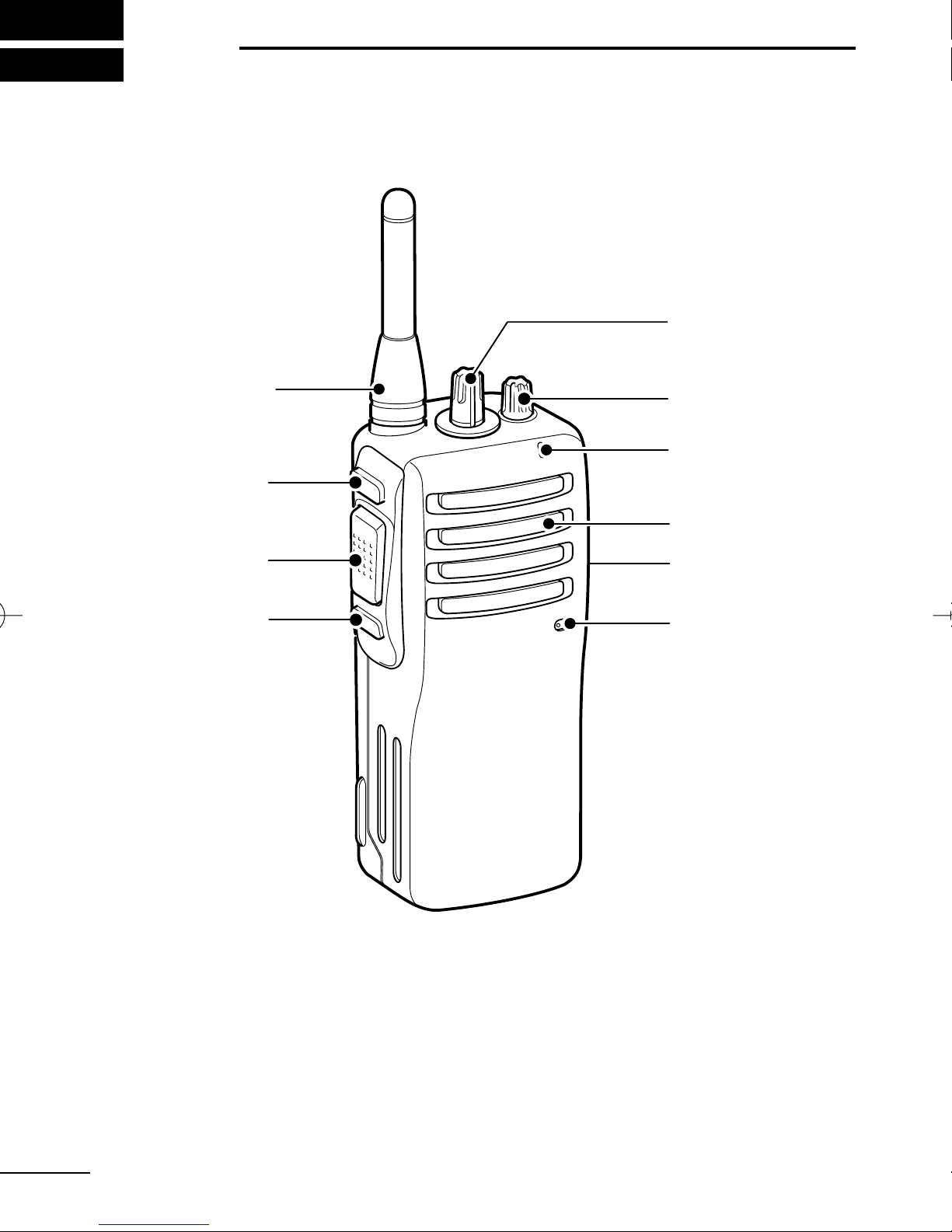
2 PANEL DESCRIPTION ………………………………………………… 5–8
‘Front, top and side panels ……………………………………………… 5
‘LED indicator …………………………………………………………… 7
‘Programmable function keys …………………………………………… 8
3 BASIC OPERATION ………………………………………………… 9–17
‘ Receiving and transmitting …………………………………………… 9
‘ Setting the squelch level ……………………………………………… 11
‘ Auto scan function …………………………………………………… 11
‘ Battery type selection ………………………………………………… 12
‘ Setting the group code number ……………………………………… 13
‘ Find scan operation …………………………………………………… 17
4 RINGER FUNCTION ………………………………………………… 18–20
‘Call-Ring operation …………………………………………………… 18
‘Smart-Ring operation ………………………………………………… 19
5 OTHER FUNCTIONS………………………………………………… 21–23
‘Monitor audible function ……………………………………………… 21
‘Time-Out Timer ………………………………………………………… 21
‘Power save function …………………………………………………… 22
‘Low battery indication ………………………………………………… 22
‘Scrambler function……………………………………………………… 23
‘All reset function ……………………………………………………… 23
6 BATTERY CHARGING ……………………………………………… 24–32
‘Caution ………………………………………………………………… 24
‘Battery chargers………………………………………………………… 27
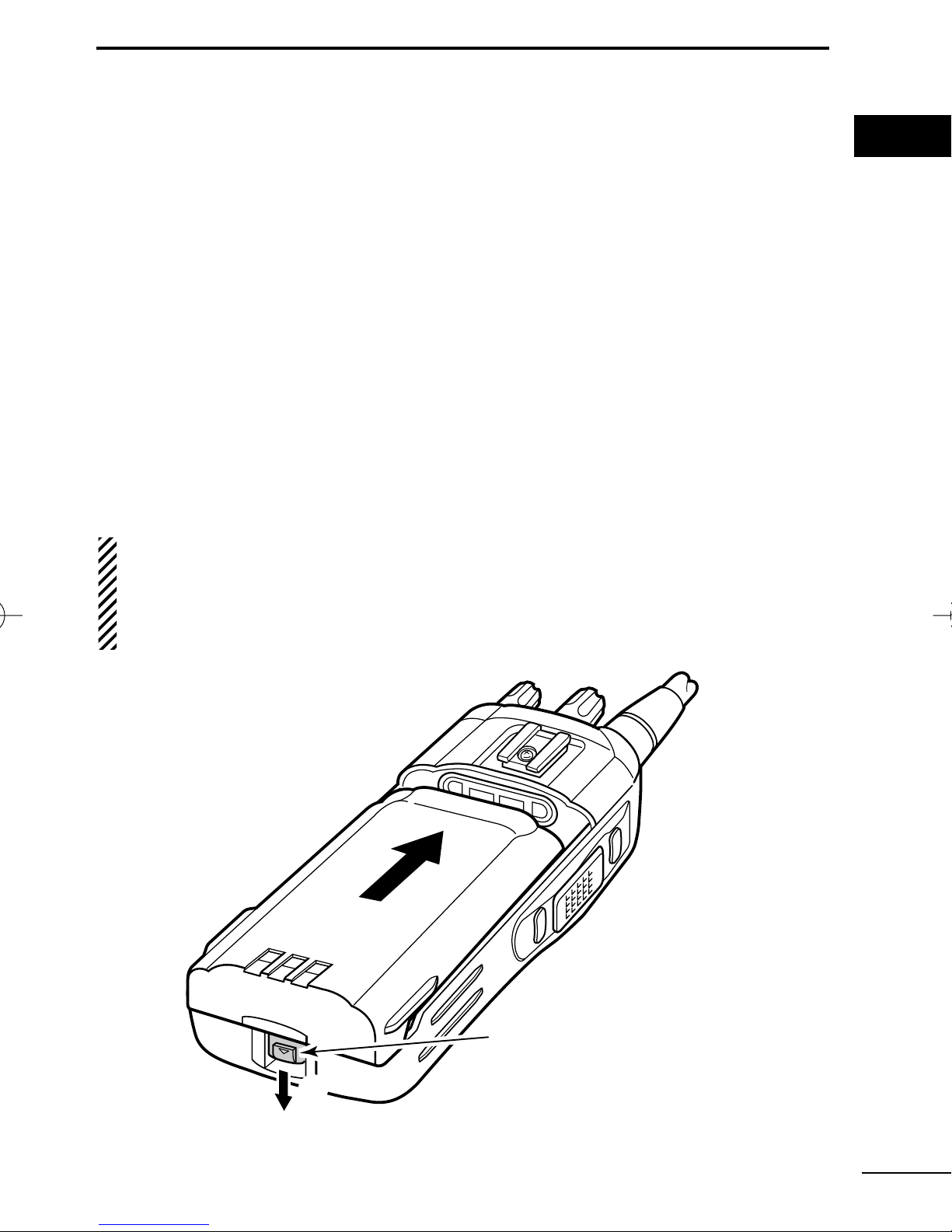
7 BATTERY CASE……………………………………………………… 33–34
‘Optional battery case (BP-240) ……………………………………… 33
8 SWIVEL BELT CLIP ………………………………………………… 35–38
‘MB-93 contents ………………………………………………………… 35
‘Attaching ………………………………………………………………… 35
‘Detaching ……………………………………………………………… 37
9 OPTIONS ……………………………………………………………… 39–40
10 SPECIFICATIONS …………………………………………………… 41–42
!IC-F25SR-0.qxd 06.10.5 6:31 PM Page iv (1,1)

1
1ACCESSORIES
■Supplied accessories
Battery pack
Belt clip Jack cover
(with screws)
AC adapter*1
(for the battery charger)
Battery charger
Unit cover*2
(double-sided tape)
Depends on version.
Use the unit cover as a spare.
Ask your dealer for details.
*1
*2
!IC-F25SR-0.qxd 06.10.5 6:31 PM Page 1 (1,1)

2
1
ACCESSORIES
1
■Accessory attachments
ïBattery pack
To attach the battery pack:
Slide the battery pack in the direction of the arrow (q), then lock it
with the battery release button.
•Slide the battery pack until the battery release button makes a ‘click’
sound.
To release the battery pack:
Push the battery release button in the direction of the arrow (w).
Then slide the battery pack in the direction opposite to the arrow
(q).
NEVER release or attach the battery pack when the transceiver
is wet or soiled. This may result in water or dust getting into the
transceiver/battery pack and may result in the transceiver being
damaged.
q
w
Battery release button
!IC-F25SR-0.qxd 06.10.5 6:31 PM Page 2 (1,1)

3
1ACCESSORIES
DBelt clip
To attach the belt clip:
qRelease the battery pack if it is attached.
wSlide the belt clip in the direction of the arrow until the belt clip is
locked and makes a ‘click’sound.
To detach the belt clip:
qRelease the battery pack if it is attached.
wPinch to lift the clip (q), and slide the belt clip in the direction of
arrow (w).
q
w
!IC-F25SR-0.qxd 06.10.5 6:31 PM Page 3 (1,1)

4
1
ACCESSORIES
1
ïJack cover
Attach the jack cover when the optional speaker-microphone or
headset is not used.
CAUTION!: Use the supplied screws only.
w
q
q
q
w
[MIC/SP] jack
Jack cover
To attach the jack cover:
qAttach the jack cover to the
[MIC/SP] jack.
wTighten the screws using a
Phillips screwdriver.
To detach the jack cover:
qUnscrew the screws using a
Phillips screwdriver.
wDetach the jack cover for the
optional speaker-microphone
or headset connection.
!IC-F25SR-0.qxd 06.10.5 6:31 PM Page 4 (1,1)

5
2PANEL DESCRIPTION
■Front, top and side panels
qCHANNEL SELECTOR [CH selector]
Rotate to select the pre-programmed memory channels.
wVOLUME CONTROL [VOL]
Rotate to turn the power ON/OFF and adjust the audio level.
r
w
y
u
e
Microphone
Speaker
t
Antenna
q
!IC-F25SR-0.qxd 06.10.5 6:31 PM Page 5 (1,1)

6
2
PANEL DESCRIPTION
2
eLED INDICATOR (p. 7)
➥Lights red while transmitting.
➥Lights green while receiving a signal, or when the squelch is
open.
➥Blinks orange after transmitting/receiving a Smart-Ring call.
➥Blinks green to indicate the low battery condition.
rEXTERNAL MICROPHONE/SPEAKER JACK [MIC/SP]
Connect an optional speaker-microphone or headset.
tPROGRAMMABLE KEY [Lower]
The desired function can be assigned. (p. 8)
yPTT SWITCH [PTT]
Push and hold to transmit; release to receive.
uPROGRAMMABLE KEY [Upper]
The desired function can be assigned. (p. 8)
Jack cover
NOTE: Attach the jack cover
when optional equipment is
not used.
See page 4 for details.
!IC-F25SR-0.qxd 06.10.5 6:31 PM Page 6 (1,1)

7
2PANEL DESCRIPTION
‘‘LED indicator
The LED indicator indicates the information as
follows;
(Ref.; R=Red, G=Green, O=Orange)
R R R R
O O
G G G G
G G
G
G G
RR
R (O)*
•TX: Turns Red while transmitting a signal.
•RX: Turns Green while receiving a signal.
•Call LED (Blink): Transmitting or receiving the Smart-Ring.
•Auto/Find scan: Blinks while Auto/Find scan is activated.
•Low BATT1: You should charge the battery. (blinks slowly)
•Low BATT2: You must charge the battery. (blinks fast)
•TX low BATT1: Low BATT1 was detected during TX mode.
•TX low BATT2: Low BATT2 was detected during TX mode.
* During the alkaline battery operation.
!IC-F25SR-0.qxd 06.10.5 6:31 PM Page 7 (1,1)

8
2
PANEL DESCRIPTION
2
‘‘Programmable function keys
The desired key function can be assigned to [Upper] and [Lower]
in following way.
qTurn power OFF in advance.
wRotate [CH selector] to select channel 16.
eRotate [VOL] to turn power ON while pushing and holding the
desired key, [Upper] or [Lower], to be assigned.
•The beep is emitted depending on the selected function as below.
rTurn power OFF.
tRepeat steps eand runtil the desired key function is assigned.
NULL KEY
No function.
SMART RING/RINGER KEY
➥Push to send a Smart-Ring call.
➥Push and hold for 1 sec. to send a Call-Ring.
MONITOR KEY
➥Push to mute the CTCSS (or DTCS) squelch mute.
➥Push and hold for 1 sec. to release the CTCSS (or DTCS)
squelch mute.
➥Open any squelch/deactivate any mute while pushing and hold-
ing this key.
VOICE SCRAMBLER FUNCTION KEY
➥Push to turn the voice scrambler function OFF.
➥Push and hold for 1 sec. to turn the voice scrambler function ON.
[Smart Ring/Ringer]
[Moni]
[Scrambler]
[Null]
1 high beep is emitted.
2 high beeps are emitted.
3 high beeps are emitted.
1 high beep is emitted for 1 sec.
!IC-F25SR-0.qxd 06.10.5 6:31 PM Page 8 (1,1)

9
3BASIC OPERATION
■Receiving and transmitting
Prior to using the transceiver for the first time, the battery pack
must be fully charged for optimum life and operation. (P. 24)
Receiving:
qRotate [VOL] clockwise to turn power
ON.
wRotate [CH selector] to select the de-
sired operating channel.
•Set your group code number if required.
(pgs. 13–16)
•Scan starts automatically when channel
16 is selected. (p. 11)
eListen for a transmission and adjust
[VOL] to a comfortable listening level.
•The LED indicator turns green, when
the received signal contains the same
CTCSS tone or DTCS code.
•When no transmission is heard, push
and hold [MONI] while adjusting [VOL].
rThe transceiver is now set to receive desired calls on the se-
lected channel.
Transmitting:
Wait for the channel to become clear to avoid interference.
qWhile pushing and holding [PTT], speak into the microphone at
a normal voice level.
•The LED indicator turns red.
wRelease [PTT] to return to receive.
IMPORTANT!: To maximize the readability of your signal;
1. Pause briefly after pushing [PTT].
2. Hold the microphone 5 to 10 cm from your lips, then speak
into the microphone at a normal voice level.
[VOL]
[CH selector]
Microphone
!IC-F25SR-0.qxd 06.10.5 6:31 PM Page 9 (1,1)

10
3
BASIC OPERATION
3
DDFrequency channel/CTCSS tone list (default)
*1All operating channel frequencies cannot be changed.
*2CTCSS tones can be programmed. You can use DTCS (Digital Tone
Code Squelch) instead of CTCSS. (p. 15)
Frequency (MHz)*1
446.006250
446.018750
446.031250
446.043750
446.056250
446.068750
446.081250
446.093750
446.006250
446.018750
446.031250
446.043750
446.056250
446.068750
446.081250
Auto Scan
Tone (Hz)*2
No setting
No setting
No setting
107.2
110.9
114.8
118.8
123.0
127.3
131.8
136.5
141.3
146.2
151.4
156.7
—
CH
1
2
3
4
5
6
7
8
9
10
11
12
13
14
15
16
!IC-F25SR-0.qxd 06.10.5 6:31 PM Page 10 (1,1)

11
3BASIC OPERATION
‘‘Setting the squelch level
The squelch circuit mutes the received audio signal depending on
the signal strength.
qTurn power OFF in advance.
wWhile pushing and holding [PTT]
and [Lower], rotate [VOL] to
turn power ON to enter the
squelch adjustment mode.
•A beep (Pi) is emitted.
ePush [Upper] to increase the
squelch level (tight squelch) or
[Lower] to decrease the squelch
level (loose squelch).
•Squelch level will be fixed after 1
sec.
rTurn power OFF, then ON again.
‘‘Auto scan function
Auto scan function proceeds from lower channel to higher channel
numbers in sequence. Scanning searches for signals automatically
and makes it easier to locate new stations for contact or listening
purposes.
qRotate [CH selector] to select
channel 16.
wScan starts automatically.
•The LED indicator blinks green
slowly.
•When receiving a signal, scan
pauses until the signal disap-
pears.
[Upper]
[VOL]
[Lower]
[PTT]
[CH selector]
!IC-F25SR-0.qxd 06.10.5 6:31 PM Page 11 (1,1)

12
3
BASIC OPERATION
3
‘‘Battery type selection
The battery type MUST be selected according to the type of bat-
tery attached when turning the transceiver ON.
Ask your dealer for details.
NOTE: When the selected battery type is not matched to the at-
tached battery, the transceiver does not work correctly.
qTurn power OFF in advance.
wWhile pushing and holding [PTT],
rotate [VOL] to turn power ON.
eAfter the transceiver is powered
ON, you should hold [PTT] for 5
sec. to toggle the attached battery
type.
•When the Lithium-Ion battery type is
selected, a beep (Pi) is emitted after
a 5 sec. count.
•When the Alkaline battery type is
selected, 2 beeps (PiPi) are emitted
after a 5 sec. count.
In this case, the LED indicator turns
orange while transmitting a signal.
[VOL]
[PTT]
!IC-F25SR-0.qxd 06.10.5 6:31 PM Page 12 (1,1)

13
3BASIC OPERATION
‘‘Setting the group code number
DDCTCSS tone setting
The transceiver is equipped with 50 CTCSS tones and OFF. CTCSS
operation provides communication with silent standby since you will
only receive calls from group members using the same CTCSS tone.
qTurn power OFF in advance.
wWhile pushing and holding [PTT], [Upper] and [Lower], rotate
[VOL] to turn the power ON.
eRotate [CH selector] to select the desired channel (1 to 15) that
you want to assign the CTCSS tone to.
rPush and hold [Upper] until a long beep is emitted.
tPush [PTT] the necessary number of times to choose the 10
digit of the desired CTCSS tone number (grey column) from the
list at right.
yPush [Upper].
•Confirmation beep(s) is (are) emitted. (See the Confirmation beep
list at right.)
uPush [PTT] the necessary number of times to choose the 1 digit
of the desired CTCSS tone number (grey column) from the list at
right.
iPush [Upper] to complete the setting.
•Confirmation beep(s) is (are) emitted. (See the Confirmation beep
list at right.)
oTurn power OFF, then ON again.
[Example]: Tone No. 28 (162.2 Hz) assignment to channel 4
qTurn power OFF in advance.
wWhile pushing and holding [PTT], [Upper] and [Lower], rotate
[VOL] to turn the power ON.
eRotate [CH selector] to select channel 4, then push and hold
[Upper] until a long beep is emitted.
!IC-F25SR-0.qxd 06.10.5 6:31 PM Page 13 (1,1)

14
3
BASIC OPERATION
3
rPush [PTT] twice to choose the 2 (10 digit) of the tone number
28.
tPush [Upper] (2 short beeps are emitted,) then push [PTT] eight
times to choose the 8 (1 digit) of the tone number 28.
yPush [Upper] to complete the setting.
•A long beep and 3 short beeps are emitted.
uTurn power OFF, then ON again.
• Available CTCSS tone list (Hz)
• Confirmation beep list
●: Short beep : Long beep
Push [PTT] Confirmation beep
●
●
●●
●●●
●●●●
Push [PTT] Confirmation beep
●●●●●
●
●●
●●●
●●●●
No push
1 (Once)
2 (Twice)
3 (Third)
4 (Fourth)
5 (Fifth)
6 (Sixth)
7 (Seventh)
8 (Eighth)
9 (Ninth)
Freq.
67.0
69.3
71.9
74.4
77.0
79.7
82.5
85.4
88.5
91.5
No.
01
02
03
04
05
06
07
08
09
10
Freq.
94.8
97.4
100.0
103.5
107.2
110.9
114.8
118.8
123.0
127.3
No.
11
12
13
14
15
16
17
18
19
20
Freq.
131.8
136.5
141.3
146.2
151.4
156.7
159.8
162.2
165.5
167.9
No.
21
22
23
24
25
26
27
28
29
30
Freq.
171.3
173.8
177.3
179.9
183.5
186.2
189.9
192.8
196.6
199.5
No.
31
32
33
34
35
36
37
38
39
40
Freq.
203.5
206.5
210.7
218.1
225.7
229.1
233.6
241.8
250.3
254.1
OFF
No.
41
42
43
44
45
46
47
48
49
50
00
!IC-F25SR-0.qxd 06.10.5 6:31 PM Page 14 (1,1)

15
3BASIC OPERATION
DDDTCS code setting
This transceiver is equipped with 84 DTCS codes and OFF.
DTCS operation provides communication with silent standby since
you will only receive calls from group members using the same
DTCS code.
qTurn power OFF in advance.
wWhile pushing and holding [PTT], [Upper] and [Lower], rotate
[VOL] to turn the power ON.
eRotate [CH selector] to select the desired channel (1 to 15) that
you want to assign the DTCS code to.
rPush and hold [Lower] until a long beep is emitted.
tPush [PTT] the necessary number of times to choose the 10
digit of the desired DTCS code number (grey column) from the
list at right.
yPush [Upper].
•Confirmation beep(s) is (are) emitted. (See the Confirmation beep
list on p. 14.)
uPush [PTT] the necessary number of times to choose the 1 digit
of the desired DTCS code number (grey column) from the list at
right.
iPush [Upper].
•Confirmation beep(s) is (are) emitted. (See the Confirmation beep
list on p. 14.)
oIf you want to use Inverse mode, push [PTT] once more.
*You can skip this step, if you want to use Normal mode.
!0 Push [Upper] to complete the setting.
•A short beep is emitted.
!1 Turn power OFF, then ON again.
[Example]: Code No. 16 (114) with Inverse mode assignment to
channel 5
qTurn power OFF in advance.
wWhile pushing and holding [PTT], [Upper] and [Lower], rotate
[VOL] to turn the power ON.
!IC-F25SR-0.qxd 06.10.5 6:31 PM Page 15 (1,1)
Other manuals for IC-F25SR
1
Table of contents
Other Icom Transceiver manuals

Icom
Icom IC-F5061/D User manual

Icom
Icom UHF IC-F60 User manual

Icom
Icom IC-M304 User manual

Icom
Icom IC-FR4000 Series User manual

Icom
Icom IC-7851 User manual

Icom
Icom IC-746 Installation guide

Icom
Icom IC-04A User manual

Icom
Icom IC-F7000 User manual

Icom
Icom IC-04A User manual

Icom
Icom IC-2300H Installation and operating instructions

Icom
Icom VHF IC-F50 User manual

Icom
Icom IC-745 User manual

Icom
Icom IC-701 User manual

Icom
Icom IC-718 Installation and operating instructions

Icom
Icom IC-M502AW User manual

Icom
Icom IC-M504 User manual

Icom
Icom IC-229A User manual

Icom
Icom IC-2200H User manual

Icom
Icom IC-M801E User manual

Icom
Icom IC-M88 User manual