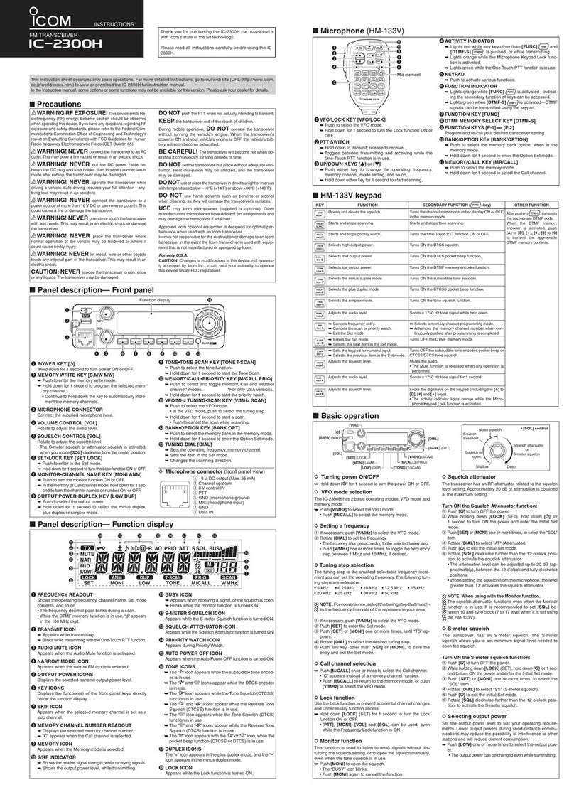
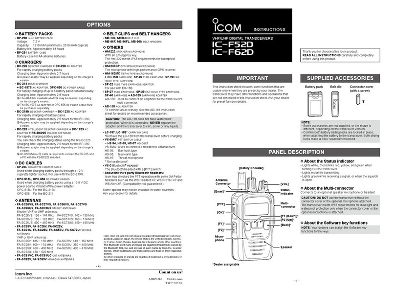
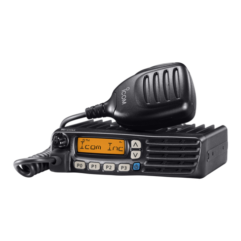
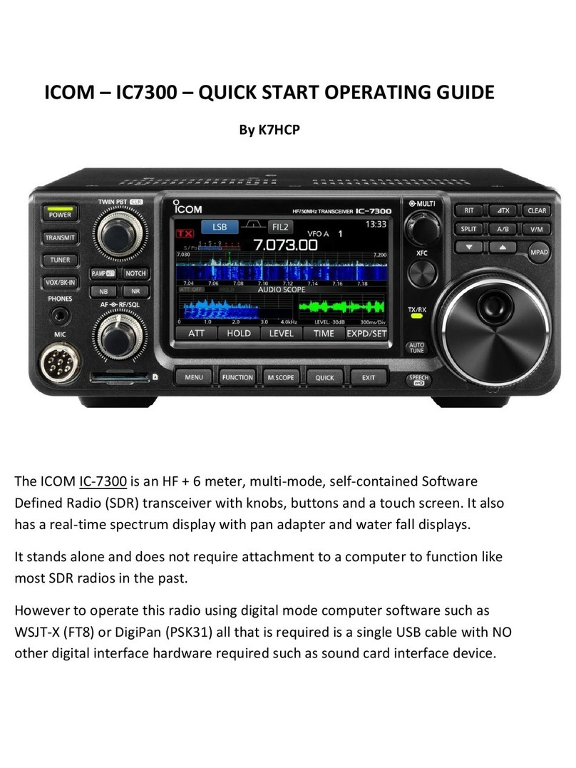
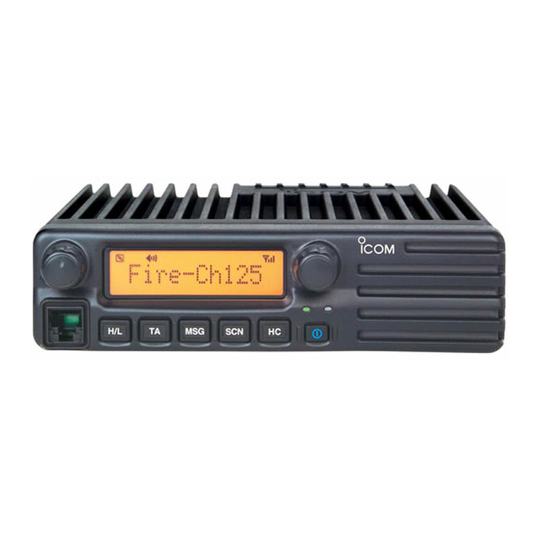
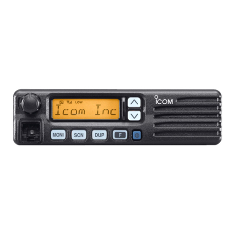
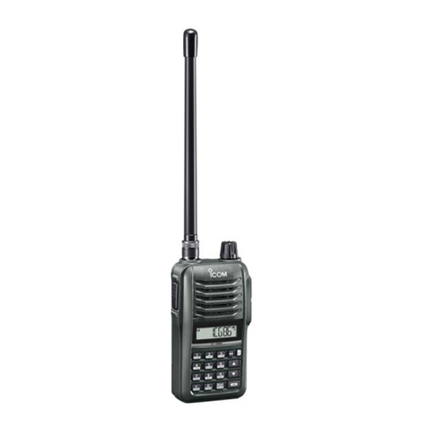
Icom IC-208H Guide


6
1 PREPARATION
When adjusting IC-208H, need to enter adjustment mode and the JIG cable is required.
■REQUIRED TEST EQUIPMENT
DC power supply
RF power meter
(terminated type)
Frequency counter
Standard signal
generator (SSG)
FM deviation meter
Oscilloscope
Audio generator
Attenuator
EQUIPMENT GREDE AND RANGE EQUIPMENT GREDE AND RANGE
IC-208H ADJUSTMENT PROCEDURES
Output voltage : 13.8 V DC
Current capacity : 12 A or more
Measuring range : 0.1–100 W
Frequency range : 1.8–600 MHz
Impedance : 50 Ω
SWR : Less than 1.2 : 1
Frequency range : 0.1–600 MHz
Frequency accuracy : ±1 ppm or better
Sensitivity : 100 mV or better
Frequency range : 0.1–1200 MHz
Output level : 0.1 µV–32 mV
(–127 to –17 dBm)
Frequency range : 0–600 MHz
Measuring range : 0 to ±5 kHz
Frequency range : DC–600 MHz
Measuring range : 0.01–10 V
Frequency range : 300–3000 Hz
Measuring range : 1–500 mV
Power attenuation : 50 or 60 dB
Capacity : 150 W or more
■ENTERING THE ADJUSTMENT MODE
qTurn the transceiver’s power OFF..
wConnect the JIG cable to the [MIC] jack.
ePush and hold the [SET] and [BAND] keys, and then turn power ON.
NOTE:Exiting from the adjustment mode when the transciever’s power is OFF.
■OPERATING ON THE ADJUSTMENT MODE
•Change the adjustment value : [DIAL]
•Verifying the adjustment value : [M/CALL] key
•Forward the adjustment item : [SET/LOCK] key
•Go back the adjustment item : [S.MW/MW] key
•Store the adjustment value in the memory : [BAND] key
CAUTION:Need to push the [BAND] key when storing the adjustment value in the memory. Otherwise, the transceiver is not
adjusted properly.
NOTE: *Need to adjust about manually adjustment items (shown pages 3, 4 and 5)
ADJUSTMENT ITEMS
FREQUENCY
REFERENCE VOLATGE
PROTECT TIME
PROTECT TEMPERATURE
FAN TEMPERATURE
*DTCS
SIGNAL OUTPUT
*S-METER
*SQUELCH LEVEL (WIDE)
*SQUELCH LEVEL (NARROW)
DISPLAY
[Fr1]–[Fr8]
[rE–], [rE+]
[PT]
[PCV], [PCU]
[FT]
[DTA], [DTB]
[DT], [CT]
[SL]
[SqW]
[SqN]
CAUTION!: DO NOT adjust following adjusment items (Because they are adjusted automatically when other
adjustments are adjusted). Otherwise, the transceiver do not work properly.
7
2 SOFTWARE ADJUSTMENT
REFERENCE
FREQUENCY
[Fr]
REFERENCE
VOLTAGE
[rE]
VHF
OUTPUT
POWER
(High)
[POH]
(Middle)
[POM]
(Low)
[POL]
UHF
OUTPUT
POWER
(High)
[POH]
(Middle)
[POM]
(Low)
[POL]
TRANSMIT
MINIMUM
VOLTAGE
[PL]
PROTECT
VOLTAGE
[PV]
1
1
1
2
3
1
2
3
1
2
3
1
2
•Operating frequency : 445.0 MHz
•Loosely couple a frequency counter to the antenna
connector on the rear panel.
•Transmitting
•Operating frequency : 445.0 MHz
•Receiving
•Operating frequency : 146.0 MHz
•Connect an RF power meter to the antenna connector.
•Transmitting
•Transmitting
•Transmitting
•Operating frequency : 445.0 MHz
•Connect an RF power meter to the antenna connector.
•Transmitting
•Transmitting
•Transmitting
•Operating frequency : 440.0 MHz
•Connect an RF power meter to the antenna connector.
•Transmitting
•Operating frequency : 445.0 MHz
•Transmitting
•Operating frequency : 450.0 MHz
•Transmitting
•Operating frequency : 146.0 MHz
•[High]/[Middle]/[Low] swtich : High
•Connect an RF power meter to the antenna connector.
•Transmitting
•Operating frequency : 445.0 MHz
•Transmitting
•Turn the [DIAL] to set to 445.0000 MHz.
•Push the [BAND] key.
•Turn the [DIAL] to set the VHF high power to 55 W.
•Push the [BAND] key.
•
Turn the [DIAL] to set the VHF middle power to 15 W.
•Push the [BAND] key.
•Turn the [DIAL] to set the VHF low power to 5 W.
•Push the [BAND] key.
•Turn the [DIAL] to set the UHF high power to 55 W.
•Push the [BAND] key.
•
Turn the [DIAL] to set the UHF middle power to 15 W.
•Push the [BAND] key.
•Turn the [DIAL] to set the UHF low power to 5 W.
•Push the [BAND] key.
•Turn the [DIAL] to set to 1 W.
•Push the [BAND] key.
•Turn the [DIAL] to set to 1 W.
•Push the [BAND] key.
•Turn the [DIAL] to set to 1 W.
•Push the [BAND] key.
ADJUSTMENT ADJUSTMENT CONDITION OPERATION

8
SOFTWARE ADJUSTMENT-Continued
FREQUENCY
DEVIATION
(VHF band)
[DE]
(UHF band)
[DE]
DTCS WAVE
FORM
(VHF band)
[DE]
(UHF band)
[DE]
TRACKING
(Low band)
[Tr]
(Middle1
band)
[Tr]
1
2
3
4
1
2
1
2
3
4
5
6
7
8
•Operating frequency : 144.0 MHz
•Connect an audio generator to the [MIC] jack and set
as : +20 dB
•Connect an FM deviation meter to the antenna con-
nector and set as :
HPF : 50 Hz
LPF : 20 kHz
De-emphasis : OFF
Detector : (P–P)/2
•Transmitting
•Operating frequency : 148.0 MHz
•Transmitting
•Operating frequency : 440.0 MHz
•Transmitting
•Operating frequency : 450.0 MHz
•Transmitting
•Operating frequency : 146.0 MHz
•No audio signal is applied to the [MIC] jack.
•DTCS code : 007
•Set an FM deviation meter as:
HPF : OFF
LPF : 20 kHz
De-emphasis : OFF
Detector : (P–P)/2
•Transmitting
•Operating frequency : 445.0 MHz
•Transmitting
•Operating frequency : 118.1 MHz
•Connect an SSG to the antenna connector and set as
Level : 1 µV* (–107 dBm)
Modulation : 1 kHz
Deviation : ± 3.5 kHz
•Receiving
•Operating frequency : 146.1 MHz
•Receiving
•Operating frequency : 160.1 MHz
•Receiving
•Operating frequency : 173.9 MHz
•Receiving
•Operating frequency : 230.1 MHz
•Connect an SSG to the antenna connector and set as
Level : 1 µV* (–107 dBm)
Modulation : 1 kHz
Deviation : ± 3.5 kHz
•Receiving
•Operating frequency : 260.1 MHz
•Receiving
•Operating frequency : 380.1 MHz
•Receiving
•Operating frequency : 399.9 MHz
•Receiving
•Turn the [DIAL] to set to ±4.6 kHz.
•Push the [BAND] key.
•Turn the [DIAL] to set to ±4.6 kHz.
•Push the [BAND] key.
•Turn the [DIAL] to set to ±4.6 kHz.
•Push the [BAND] key.
•Turn the [DIAL] to set to ±4.6 kHz.
•Push the [BAND] key.
•Turn the [DIAL] to set to flat wave form as shown
below.
•Push the [BAND] key.
•Turn the [DIAL] to set to flat wave form as same as
VHF band.
•Push the [BAND] key.
ADJUSTMENT ADJUSTMENT CONDITION OPERATION
*This output level of a standard signal generator (SSG) is indicated as SSG’s open circuit.
Set to square wave
form

9
SOFTWARE ADJUSTMENT-Continued
TRACKING
(Middle2
band)
[Tr]
(High band)
[Tr]
S-METER
[SL]
9
10
11
12
13
14
15
1
2
3
4
•Operating frequency : 400.1 MHz
•Connect an SSG to the antenna connector and set as
Level : 1 µV* (–107 dBm)
Modulation : 1 kHz
Deviation : ± 3.5 kHz
•Receiving
•Operating frequency : 429.9 MHz
•Receiving
•Operating frequency : 480.1 MHz
•Receiving
•Operating frequency : 549.9 MHz
•Receiving
•Operating frequency : 810.1 MHz
•Connect an SSG to the antenna connector and set as
Level : 1 µV* (–107 dBm)
Modulation : 1 kHz
Deviation : ± 3.5 kHz
•Receiving
•Operating frequency : 905.1 MHz
•Receiving
•Operating frequency : 999.9 MHz
•Receiving
•Operating frequency : 146.1 MHz
•Connect an SSG to the antenna connector and set as
Level : 1 µV* (–107 dBm)
Modulation : 1 kHz
Deviation : ± 3.5 kHz
•Receiving
•Operating frequency : 445.1 MHz
•Receiving
•Operating frequency : 435.9 MHz
•Receiving
•Operating frequency : 810.1 MHz
•Set an SSG as
Level : 5.6 µV* (–92 dBm)
Modulation : 1 kHz
Deviation : ± 3.5 kHz
•Receiving
•Push the [BAND] key.
ADJUSTMENT ADJUSTMENT CONDITION OPERATION
*This output level of a standard signal generator (SSG) is indicated as SSG’s open circuit.

10
SOFTWARE ADJUSTMENT-Continued
SQUELCH
LEVEL
(Wide)
[SqW]
(Narrow)
[SqN]
TEMP.
CORRECTION
<High power>
(VHF –10˚C)
[HP–]
(VHF +60˚C)
[HP–]
<Mid. power>
(VHF –10˚C)
[MP–]
(VHF +60˚C)
[MP–]
<Low power>
(VHF –10˚C)
[LP–]
(VHF +60˚C)
[LP–]
1
2
3
4
5
6
7
8
1
2
3
4
5
6
•Operating frequency : 146.1 MHz
•Connect an SSG to the antenna connector and set as
Level : 0.079 µV* (–129 dBm)
Modulation : 1 kHz
Deviation : ± 3.5 kHz
•Receiving
•Operating frequency : 445.1 MHz
•Receiving
•Operating frequency : 435.1 MHz
•Set an SSG as:
Level : 0.1 µV* (–127 dBm)
•Receiving
•Operating frequency : 810.1 MHz
•Set an SSG as:
Level : 0.25 µV* (–119 dBm)
•Receiving
•Operating frequency : 146.1 MHz
•Connect an SSG to the antenna connector and set as
Level : 0.071 µV* (–130 dBm)
Modulation : 1 kHz
Deviation : ± 3.5 kHz
•Receiving
•Operating frequency : 445.1 MHz
•Receiving
•Operating frequency : 435.1 MHz
•Set an SSG as:
Level : 0.1 µV* (–127 dBm)
•Receiving
•Operating frequency : 810.1 MHz
•Set an SSG as:
Level : 0.25 µV* (–119 dBm)
•Receiving
•Operating frequency : 146.0 MHz
•Receiving
•Operating frequency : 146.0 MHz
•Receiving
•Operating frequency : 146.0 MHz
•Receiving
•Operating frequency : 146.0 MHz
•Receiving
•Operating frequency : 146.0 MHz
•Receiving
•Operating frequency : 146.0 MHz
•Receiving
•Push the [BAND] key.
•Turn the [DIAL] to set to “F9”on the display.
•Push the [BAND] key.
•Turn the [DIAL] to set to “F9”on the display.
•Push the [BAND] key.
•Turn the [DIAL] to set to “F9”on the display.
•Push the [BAND] key.
•Turn the [DIAL] to set to “F9”on the display.
•Push the [BAND] key.
•Turn the [DIAL] to set to “F9”on the display.
•Push the [BAND] key.
•Turn the [DIAL] to set to “F9”on the display.
•Push the [BAND] key.
ADJUSTMENT ADJUSTMENT CONDITION OPERATION
*This output level of a standard signal generator (SSG) is indicated as SSG’s open circuit.

11
SOFTWARE ADJUSTMENT-Continued
TEMP.
CORRECTION
<High power>
(UHF –10˚C)
[HP–]
(UHF +60˚C)
[HP–]
<Mid. power>
(UHF –10˚C)
[MP–]
(UHF +60˚C)
[MP–]
<Low power>
(UHF –10˚C)
[LP–]
(UHF +60˚C)
[LP–]
PROTECT
SCALE
(VHF)
[PM]
(UHF)
[PM]
PROTECT
POWER
(VHF)
[PP]
(UHF)
[PP]
1
2
3
4
5
6
1
2
1
2
•Operating frequency : 445.0 MHz
•Receiving
•Operating frequency : 445.0 MHz
•Receiving
•Operating frequency : 445.0 MHz
•Receiving
•Operating frequency : 445.0 MHz
•Receiving
•Operating frequency : 445.0 MHz
•Receiving
•Operating frequency : 445.0 MHz
•Receiving
•Operating frequency : 146.0 MHz
•Receiving
•Operating frequency : 445.0 MHz
•Receiving
•Operating frequency : 146.0 MHz
•Receiving
•Operating frequency : 445.0 MHz
•Receiving
•Turn the [DIAL] to set to “F9”on the display.
•Push the [BAND] key.
•Turn the [DIAL] to set to “07”on the display.
•Push the [BAND] key.
•Turn the [DIAL] to set to “00”on the display.
•Push the [BAND] key.
•Turn the [DIAL] to set to “00”on the display.
•Push the [BAND] key.
•Turn the [DIAL] to set to “00”on the display.
•Push the [BAND] key.
•Turn the [DIAL] to set to “00”on the display.
•Push the [BAND] key.
•Turn the [DIAL] to set to 130 % on the display.
•Push the [BAND] key.
•Turn the [DIAL] to set to 140 % on the display.
•Push the [BAND] key.
•Turn the [DIAL] to set to 5 W on the display.
•Push the [BAND] key.
•Turn the [DIAL] to set to 5 W on the display.
•Push the [BAND] key.
ADJUSTMENT ADJUSTMENT CONDITION OPERATION
Other manuals for IC-208H
3
This manual suits for next models
1
Table of contents
Other Icom Transceiver manuals
Popular Transceiver manuals by other brands

evertz
evertz 7707IT manual

Microwave Data Systems
Microwave Data Systems MDS 2710D Installation & operation guide

Standard Horizon
Standard Horizon QUANTUM GX6500E owner's manual

Kenwood
Kenwood Nexedge NX-820H Service manual

ATC Technology
ATC Technology ATC-2000WF user manual

Vertex Standard
Vertex Standard GX1600 Alignment Guide

Semtech
Semtech SX1261 user guide

Super Star
Super Star 360 owner's manual

Kenwood
Kenwood NX-3000 series user guide

General Lee
General Lee Full Channel AM/FM Amateur Mobile... owner's manual

NavCom Technology
NavCom Technology NavComm SL30 user guide

QRPGuys
QRPGuys Digital DSB II Transceiver Kit instructions