manuals.online logo
Brands
  1. Home
  2. •
  3. Brands
  4. •
  5. Icom
  6. •
  7. Transceiver
  8. •
  9. Icom IC-7100 User manual

Icom IC-7100 User manual

1
Quick-Start Guide
for the IC-7100
prepared by KN3U
Version 5.1
4/4/2019
Figure 1
A. On/Off/Volume/Squelch
The knob at the top left of the front panel (in Figure 1) is the volume control. Press it
to turn the radio on. Press and hold to turn the radio off.
The ring around the volume control knob (in Figure 1) serves as the squelch control on
2 m / 70 cm FM, and as the RF gain control on HF and 6 m. The manual describes a
number of special functions that this control can perform based on menu settings. To
avoid confusion, it would be best to stick with the default behavior. For a radio that must
be used by a number of different operators, it’s really important to keep things simple and
consistent.
2
Figure 2
B. Menu Selection
The first thing to understand about the radio is that it has a touch screen. There are five
soft keys (virtual buttons) across the bottom of the screen, providing access to a menu of
special functions. The functions of the soft keys change depending on which menu or
sub-menu you are in. The menu that is being displayed in Figure 2 is Menu-1, as
indicated by the M-1 indication just above the left-most soft key.
To scroll through the various menus, press the MENU button repeatedly. As seen in
Figure 1, it is a “real” button, located just below the left corner of the display.
3
C. Frequency Selection
Note the primary frequency display in Figure 2. The frequency is displayed down to a
resolution of 1 Hz. (There is a menu option to hide the least significant digit and only
display frequency to the nearest 10 Hz.)
If the frequency can’t be changed. Look for the SPEECH/LOCK button, located under
the tuning dial. Press and hold for 1 second to unlock the front panel. When in the middle
of an operation, if may be helpful to lock the front panel (same way as you unlock it) so
that you don’t inadvertently tune off frequency.
Tuning using the tuning dial. The MHz digits, kHz digits, and Hz digits are three
different touch zones. Here is how to use them.
•Touch the MHz digits to select the band of operation. A popup screen lets you
make a choice. Touch and hold the MHz digits for 1 second to set the tuning rate
to 1 MHz/step if you need to quickly tune across the band.
•Touch the kHz digits to enable coarse tuning mode. Touch and hold the kHz
digits to select the coarse tuning step size. The choices are 1 kHz to 100 kHz per
step. 5 kHz is customary on 2m, and 25 kHz is customary on 70 cm. On HF,
pick a tuning step that is convenient.
•When operating on HF, touch the Hz digits to access fine tuning. Touch and hold
the Hz digits to select the fine tuning step size. The choices are 1 Hz per step or
10 Hz per step.
Direct frequency entry. The radio has provision for direct frequency entry, but it’s very
well hidden!
•Touch the MHz digits to select the band of operation. While the popup screen is
active, one of the buttons is labeled F-INP. Press that button to obtain the direct
entry screen.
•On the virtual keypad, enter the desired frequency in Mhz. In other words, use a
decimal point between the MHz and kHz digits. Or skip the decimal point and
enter sufficient trailing zeroes to put the significant digits where you want them.
•The direct entry screen has a few other tricks that we won’t go into here. See the
manual for details.
4
D. Operating Mode
The current mode of operation (FM, LSB, USB, etc.) is displayed at the top edge of the
screen. Touch the mode indicator to access a popup screen to change the operating mode.
On the popup screen, there are a number of soft keys for selecting the various modes.
•Pressing the SSB button toggles between USB and LSB.
•Press FM for operation on 2m or 70 cm.
•For Winlink operation, pressing the DATA button on the mode select popup
screen rotates through four possible data modes. When accessing a local RMS
Gateway on 2m or 70 cm, choose the FM DATA mode (FM-D is what shows on
the screen). For HF Winlink, you would choose the USB DATA mode regardless
of which HF band you are using. However, note that we don’t intend to operate
HF at Holy Cross-Germantown, given our antenna situation.
The difference between “regular” FM and FM-DATA mode is that the microphone audio
is muted in FM DATA mode. So, if you can’t get through on a voice channel and you
hear a report that “someone is transmitting an unmodulated carrier, touch the mode
indicator and the data button to exit FM DATA mode.
You can run Winlink using the “regular” FM mode, but background noise in the room
may be picked up by the microphone and corrupt the audio from the TNC.
5
E. VFOs and Memories; Repeater Operations
The radio has two VFOs, labeled A and B. In addition, there are 495 “regular” memories
plus a handful of special memories. The memories are organized in five banks of 99
memories each, called Bank A through Bank E. So the numbering scheme for memories
is as follows: A00 ~ A99, B00 ~ B99, etc.
In addition to these memories, there are two Call Channels on the 2m band, labeled 144C1
and 144C2,and two Call Channels on 70 cm, labeled 430C1 and 430C2. (This sounds
incredibly non-intuitive to me, but that’s how they did it.)
1
VFO Operation. Push the MENU button
repeatedly to access Menu-1. Touch the V/M
soft key to switch between VFO and Memory
mode. You will see the mode displayed
above the channel number. You can also
touch the channel number or VFO/MEMO
icon to toggle back and forth if you don’t
happen to be in Menu 1.
While in VFO mode, touch the A/B button to
toggle between VFO-A and VFO-B. Touch
and hold the A/B button to equalize both
VFOs to the currently displayed frequency.
Memory Operation. While in memory mode,
use the memory channel selector knob,
located below the volume knob, to select the
desired memory. The ring around the
memory channel selector knob is used to
select one of the five memory banks.
When you select a memory channel, the radio chooses the saved frequency, repeater shift,
operating mode, transmit power, tone or digital squelch encode/decode parameters, and
(on HF) filter settings. You can change any of these settings, but reselecting the same
memory a second time will restore the original (saved) settings.
Repeater Shift. The radio automatically selects the appropriate repeater shift, in
accordance with the ARRL Band Plan, when tuned to a repeater output frequency. This
setting can be overridden using the DUP (duplex) soft key found in Menu-2.
Listen on the Input. When operating on a repeater, you can temporarily reverse the
repeater input and output frequencies by holding down the XFC (Xmit Frequency Check)
1
There are also a handful of memories that are used to set limits for scanning, but we won’t go into those.
The scanning memories are labeled 1A, 1B, 2A, 2B, 3A, and 3B. Just don’t confuse memory A01 (a
regular memory channel) with memory 1A (used only with the scanning feature).
Figure 3
6
button, located below the tuning dial. This is useful for determining if you are within
simplex range of another station.
Preamp. The radio has both a receiver preamp and an attenuator on the HF bands from
160 through 15 m. On the 17, 10, and 6 m bands, there are two preamps to choose from.
On 2 m and 70 cm, there is one preamp that can be switched in and out. In general, use
the least amount of pre-amplification necessary. Excess pre-amplification can contribute
to interference from strong nearby signals. The PREAMP/ATTEN switch, located below
the display, cycles through the available options on a given band.
Transmit Power. To adjust the transmit power, press the MIC/RF POWER button
(located under the display). This brings up a popup menu where the microphone gain and
transmit power may be adjusted using the Memory Select knob and the outer ring,
respectively. Please do not adjust the microphone gain (unless you are using a different
microphone). The RF Power setting is expressed in percentage of maximum output
power, which is 100 W on HF and 6m, and 50 W on 2m and 70 cm.
If you do need to adjust the microphone gain because you are using a different
microphone or headset, be sure to restore the setting to 50% when switching back to the
factory microphone. Be kind to the operator who follows you!
CTCSS (PL) Tones. When using a repeater that requires a sub-audible tone for access,
use the MENU button to access Menu-2. Touching the TONE soft key in this menu
toggles the CTCSS encoder mode on and off. Touching and holding the TONE soft key
brings up a submenu that lets you select the frequency of the sub-audible tone.
DTMF. If you need to send a DTMF string, here’s how to do it using a virtual DTMF
keypad on the radio’s display (another extremely non-intuitive arrangement). Press the
MENU button repeatedly to get to the Menu-3 screen. Touch the DTMF soft key, then
touch the SEND soft key to open the DTMF send window. Touch “Direct Input” to
display the “DTMF DIRECT INPUT” screen. Key in the DTMF sequence, then touch
TX to transmit it.
Call Channel Operation. To access the four special call channels, select either the 2m or
70 cm. band and press the TUNER/CALL button located in the lower left corner of the
front panel. Rotate the memory select knob to access the other call channel. The Call
Channels are also available when you are in Memory Channel mode and have Bank A
selected. That’s probably the easiest way to get to them.
Here are the channel assignments:
Channel
Frequency
CTCSS
Power
Use
144C1
147.00 (-)
none
25%
Ashton 2 m Repeater
144C2
146.955 (-)
156.7
25%
MARC 2 m Repeater
430C1
443.150 (+)
none
25%
Ashton 70 cm Repeater
430C2
443.900 (+)
none
25%
MC ACS repeater (WA3YOO)
7
Channel
Frequency
CTCSS
Power
Use
A01
146.565 (S)
none
100%
MC ACS preferred simplex
A02
145.770 (S)
none
100%
Winlink via WN3R-10
A03
A04
A05
A06
A07
A08
A09
A10
A11
A12
A13
A14
A15
Programming a Memory Channel. Bank A is reserved for frequently-used frequencies
and settings used in emergency operations. If you have personal preferences for
frequencies and/or preferences that you wish so save for future use, you may use Banks B
through E for that purpose. Please do not overwrite any of the settings in the Call
Channels or Bank A memories.
While memory channels may be programmed in memory mode, it may be less confusing
to use the VFO mode to program a memory channel.
Touch the channel number or VFO/MEMO icon on the right side of the touch screen to
select VFO A or B. Set the desired contents into the VFO as described earlier in this
Quick-Start Guide.
When the radio is configured as desired, press the MENU button repeatedly until you
reach the Menu-1 screen. Rotate the BANK (outer) and/or M.CH (inner) knob on the left
side of the front panel to select the desired storage location. Touch the MW soft key for 1
second to program the selected memory channel.
If you wish to assign an alphanumeric name to your memory channel, you can do this
after you have programmed the VFO information into the channel. Please refer to Page
11-10 of the IC-7100 Advanced Instructions manual for details.
8
F. Winlink VHF Operation —Hardware Setup
The information in this section is for reference only. The radio is set up for Winlink
using the Timewave PK-96 TNC, and you should not need to access these settings in
normal operation.
The TNC is connected to the radio’s DATA2 connector. See Figure 4.
Figure 4
Several configuration parameters affect the TNC performance. These are found in the SET
mode under the Connectors and Function menus. The IC-7100 User Guide is a little
fuzzy on the details. By experimentation, here is what I found.
Parameter
Setting
Explanation
Connectors Menu
DATA OFF MOD
MIC
Sets the source of transmitted audio when in FM mode
DATA MOD
ACC
Sets the source of transmitted audio when in FM-D (data)
mode.
DATA MOD Level
50%
Sets the transmitted audio level coming from the DATA2 or
ACC connector
ACC/USB AF Level
35%
Sets the level of received audio sent to the ACC, USB, and
DATA2 outputs. Note: the received audio is unsquelched
and independent of the radio’s front-panel volume control.
ACC/USB Output
Select
AF
Set to IF when using an external Digital Radio Mondiale
decoder; otherwise, set to AF.
FUNCTION Menu
RF/SQL Control
Auto
Knob functions as a conventional RF Gain control in CW and
SSB modes, and as a conventional squelch control (with RF
gain fixed at maximum) in AM and FM modes.
9
G. Winlink VHF Operation —Laptop Setup (Windows)
We are currently operating in the BYOL (bring your own laptop) mode. We are working
on having a computer set up at the hospital with the software installed and configured.
Even if we are successful, you might want to have the software installed on your
Windows laptop (or tablet) computer as a backup.
To use the Winlink VHF mode, you will need to download and install the latest version
of the Winlink Express program on your laptop. Here’s where to get it.
https://winlink.org/WinlinkExpress
While you are there, set up a user account at Winlink.org. Be sure to create a password
and record it in a safe place (with your Intellicentrics
2
login credentials!). The software is
under active development, with frequent upgrades, so please run the Winlink program
frequently to keep it up to date.
The setup at HCGH includes a USB-to-serial converter using the FTDI chipset. On many
Windows computers, this driver is pre-installed. If you need to install a driver, look here:
https://www.ftdichip.com/Drivers/VCP.htm
Another potential stumbling block is figuring out what COM port was assigned to your
serial port by Windows. You will need this information to configure the Winlink Express
software. Plugging the same USB-to-serial converter into different USB ports on your
laptop causes Windows to assign a different COM port number, so don’t assume that it
will always be the same. You can install a simple utility called TWCOMDetect that lists
all of the active COM ports on your computer. It’s a lot easier to use than the Windows
Device Manager. You can get it here (or Google it):
http://timewave.com/support/utilities/
H. Winlink Express Operation
There are lots of guides to using Winlink Express on the Internet. So I’ll just share a few
helpful tips here that are specific to our installation.
•There is no need to initialize the COM port parameters in Windows before
running the Winlink Express program. Winlink Express takes care of that for
you. Winlink Express also initializes the TNC for you. So, once you have the
TNC connected to your laptop and determine which COM port is being used, you
are ready to go.
2
Intellicentrics is a credentials program used by registered volunteers at Holy Cross. If you have not signed
up as a hospital volunteer, disregard.
10
•It is very important that operating mode of the IC-7100 be set to FM-D when in
packet radio mode on VHF/UHF. If the received packet signal is noisy, it might
help to turn the receiver preamp (P.AMP) on. On the other hand, you need to exit
the FM DATA mode when you go back to suing voice. Please leave the radio in
FM voice mode when closing the station.
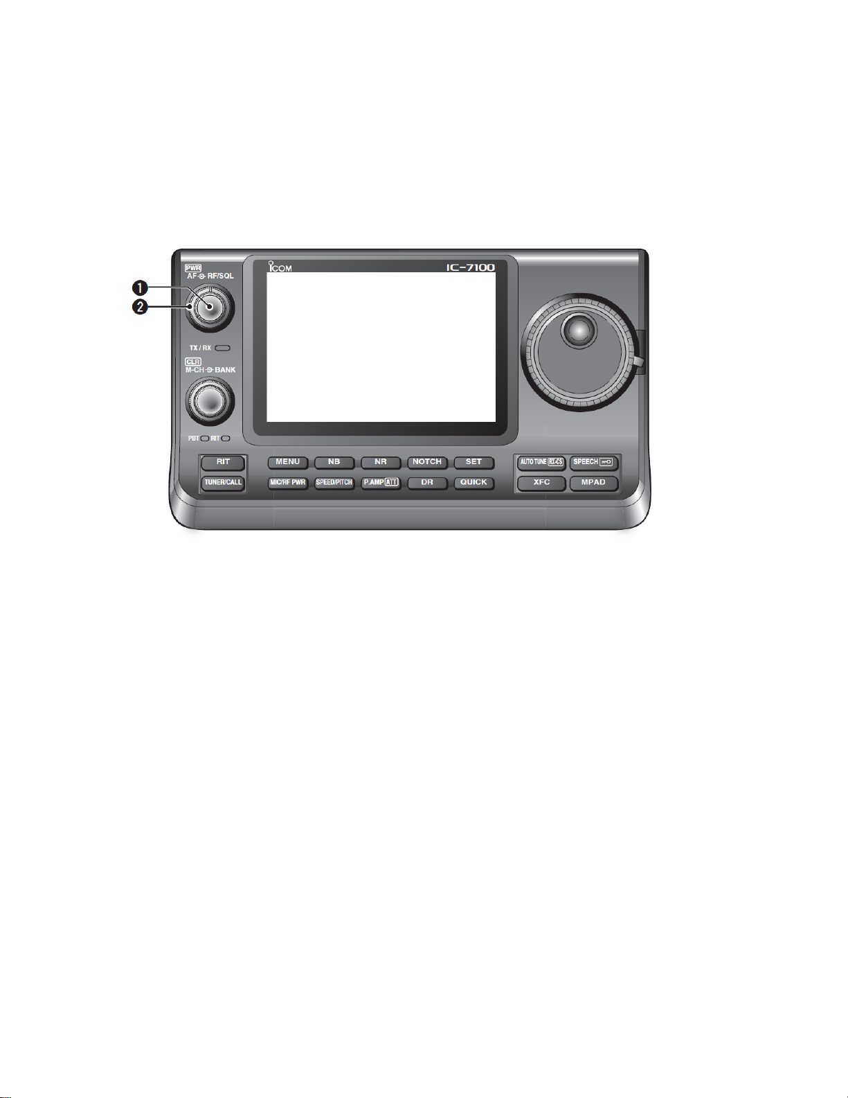
•The IC-7100 Notch Filter must be turned off during digital mode operation on any
band. (Look for the dedicated button under the display screen.) If it is
inadvertently left on, the DSP notch filter algorithm will very effectively tune out
the AFSK signal you are trying to receive, making packet connections impossible.
(Shame on Icom for not disabling this feature automatically when the radio is in
data mode, or FM mode for that matter!)
•The IF passband filter width is fixed in FM, WFM, and FM-D modes. Touching
the filter icon changes the setting, but this has no effect on the received signal.
Similarly, the noise blanker has no effect in FM mode.
•The manual is unclear about the effect of the NR (noise reduction) algorithm in
FM mode. I would recommend leaving NR off for packet operation, just to be
safe.
The first time you run Winlink Express, you will have to configure some settings. Start
the program and choose Files .. Winlink Express Setup from the menu. Enter your
callsign (with no suffix) and the password you created when you registered at
Winlink.org. While it is optional, I recommend filling in your contact information and
grid square as well. (The grid square of the hospital is FM19je.) If you have Internet
access, the program will use your grid square to provide a list of local gateway stations.
Leave the Service Code as PUBLIC. (I’m not aware of any EMCOMM gateways
operating in the local area.)
Now, you are ready to tell Winlink Express what TNC you are using. Using the dropdown
in the menu bar, select the session type as PACKET W2K and click on Open Session. This
brings up a new session window. The first time you run the program, you will probably see
an error message, which you can ignore. Click on Setup.
For the TNC Type, choose “AEA/Timewave.” The TNC Model should be “PK-96.” Select
the COM port that you previously identified, and leave the baud rate at 9600. The other
parameters can be left at default.
When you click on the Update button, the program will attempt to initialize the TNC. On
my computer, this takes almost 20 seconds, so be patient. If successful, you will see a
“Ready” message. Otherwise, you’ll have to do some troubleshooting.
Now, you are ready to make a connection. From Holy Cross - Germantown, we typically
use the WN3R-10 gateway (145.77 MHz, on Catoctin Mountain) or the WA3YOO-10
11
gateway (145.75 MHz, just across the street at Hughes). Set the IC-7100’s frequency.
3
In
the Winlink Express session window, the connection type should be “Direct” (in other
words, we are not using digipeaters to reach the gateway since these gateways are within
simplex range of the hospital). Type the callsign into the connection box, and click Start.
After a few seconds, the radio should begin transmitting and establish a connection with
the Gateway. You are off to the races!
You can also try these other stations:
Call Sign
Frequency
Location
WA3SWJ-10
145.750
Potomac, MD (Bruce may be able to point
a beam antenna at the hospital upon
request)
WA3YOO-9
145.75
Ashton, MD
WA3YOO-10
145.75
Germantown, MD
W3LRC-10
145.750
Laurel, MD
W3PGC-10
145.750
Landover Hills, MD
W3AAC-10
145.010
Millersville, MD (AA Co)
N2LEE-10
145.730
Herndon, VA4
Unfortunately, the hospital is surrounded by substantial ridges in virtually all directions.
This makes simplex VHF/UHF communications a bit of a challenge. You may or may not
be successful in reaching the stations listed above, except for WA3YOO-10, which is
literally across the street from the hospital.
In a pinch, you should be able to establish a packet peer-to-peer (PTP) connection with
another local station to relay any critical message traffic. It is also possible to make a
Winlink connection over any of the RMS Gateway stations listed above, or even over a
conventional FM repeater. (You may need to increase the TxDelay setting to several
hundred milliseconds when operating over a voice repeater.) In an emergency, when the
MCACS station at the Montgomery County EOC is activated, you can contact WA3YOO
to request assistance in relaying Winlink messages.
Version
Date
Description
1.0
4/11/2015
First draft
1.1
4/11/2015
Corrected channel assignments chart and added instructions for programming
a memory
2.0
11/28/2015
Information added on Winlink operation
3.0
12/29/2017
Updated Winlink information
4.0
??
??
5.0
10/1/2018
Updated RMS gateway list
5.1
4/4/2019
Minor edits to Winlink and memory programming sections.
3
Note that the Winlink Express program does not tune the radio when you switch to a different gateway
station. This must be done manually.
4
If you cannot connect to N2LEE-10 directly, try digipeating through the RESTON digipeater.

Other manuals for IC-7100

10

Other Icom Transceiver manuals

Icom A25C SPORT 66 USA Parts list manual

Icom

Icom A25C SPORT 66 USA Parts list manual

Icom IC-G80 User manual

Icom

Icom IC-G80 User manual

Icom IC-9100 User manual

Icom

Icom IC-9100 User manual

Icom IC-F3200DEX User manual

Icom

Icom IC-F3200DEX User manual

Icom IC-7000 User manual

Icom

Icom IC-7000 User manual

Icom IC-U81T User manual

Icom

Icom IC-U81T User manual

Icom IC-M87 User manual

Icom

Icom IC-M87 User manual

Icom ic-80fx User manual

Icom

Icom ic-80fx User manual

Icom UHF IC-F60 User manual

Icom

Icom UHF IC-F60 User manual

Icom IC-F3210D Series User manual

Icom

Icom IC-F3210D Series User manual

Icom IC-V3500 User manual

Icom

Icom IC-V3500 User manual

Icom ic-2730A Owner's manual

Icom

Icom ic-2730A Owner's manual

Icom IC-F9511S User manual

Icom

Icom IC-F9511S User manual

Icom IC-M710 User manual

Icom

Icom IC-M710 User manual

Icom IC-M90E User manual

Icom

Icom IC-M90E User manual

Icom IC-F43GT User manual

Icom

Icom IC-F43GT User manual

Icom iF110 User manual

Icom

Icom iF110 User manual

Icom IC-F21 User manual

Icom

Icom IC-F21 User manual

Icom IC-F110 User manual

Icom

Icom IC-F110 User manual

Icom IC-738 User manual

Icom

Icom IC-738 User manual

Icom IC-756PROIII User manual

Icom

Icom IC-756PROIII User manual

Icom IC-2N User manual

Icom

Icom IC-2N User manual

Icom IC-F5011 User manual

Icom

Icom IC-F5011 User manual

Icom IC-F6121D-51B User manual

Icom

Icom IC-F6121D-51B User manual

Popular Transceiver manuals by other brands

ADTRAN T200 FNID Installation and Maintenance

ADTRAN

ADTRAN T200 FNID Installation and Maintenance

Microwave Data Systems MDS 4310 Installation, Operation & Field Maintenance

Microwave Data Systems

Microwave Data Systems MDS 4310 Installation, Operation & Field Maintenance

City Theatrical Multiverse Vero 7400-5903 user manual

City Theatrical

City Theatrical Multiverse Vero 7400-5903 user manual

Galaxy DX-55V owner's manual

Galaxy

Galaxy DX-55V owner's manual

Alinco DJ-V17TFH instruction manual

Alinco

Alinco DJ-V17TFH instruction manual

Azden pcs5000 instruction manual

Azden

Azden pcs5000 instruction manual

Kenwood TW-4100A Manual guide

Kenwood

Kenwood TW-4100A Manual guide

RFM HN-1510 user guide

RFM

RFM HN-1510 user guide

Fiberplex FOI-5402 user manual

Fiberplex

Fiberplex FOI-5402 user manual

Beyerdynamic Opus 300 operating instructions

Beyerdynamic

Beyerdynamic Opus 300 operating instructions

Kenwood Nexedge NX-5400 Service manual

Kenwood

Kenwood Nexedge NX-5400 Service manual

Kenwood TK-8150 Service manual

Kenwood

Kenwood TK-8150 Service manual

Kenwood FreeTalk UBZ-GR14 instruction manual

Kenwood

Kenwood FreeTalk UBZ-GR14 instruction manual

SMSC USB3250 Specifications

SMSC

SMSC USB3250 Specifications

Johnson Controls HomeLink R171HL3 user manual

Johnson Controls

Johnson Controls HomeLink R171HL3 user manual

Vertex Standard VX-2000U Service manual

Vertex Standard

Vertex Standard VX-2000U Service manual

Bodet Lockdown Alert System Installation and user manual

Bodet

Bodet Lockdown Alert System Installation and user manual

Yaesu FT-101B instruction manual

Yaesu

Yaesu FT-101B instruction manual

manuals.online logo
manuals.online logoBrands
  • About & Mission
  • Contact us
  • Privacy Policy
  • Terms and Conditions

Copyright 2025 Manuals.Online. All Rights Reserved.