Icom IC-M45A User manual

INSTRUCTION MANUAL
iM45A
VHF MARINE TRANSCEIVER

ii
FOREWORD
Thank you for purchasing this Icom product. The IC-M45A VHF
MARINE TRANSCEIVER is designed and built with Icom’s su-
perior technology and craftsmanship. With proper care this
product should provide you with years of trouble-free operation.
IMPORTANT
READ ALL INSTRUCTIONS carefully and com-
pletely before using the transceiver.
SAVE THIS INSTRUCTION MANUAL—This in-
struction manual contains important operating instructions for
the IC-M45A.
EXPLICIT DEFINITIONS
FEATURES
☞Durable, water-resistant construction
Built tough to withstand the punishing marine environ-
ment, the IC-M45A offers reliability you can count on.
☞Dual watch and tri-watch functions
Convenient functions which allow you to monitor the dis-
tress channel (ch 16) while receiving a channel of your
choice—dual watch; or monitor the distress channel and
another channel while receiving a channel of your
choice—tri-watch.
☞Large, easy-to-read LCD
With dimensions of 20(H) ×60(W) mm, the IC-M45A’s
function display is easy to read and shows operating con-
ditions at a glance. Backlighting and contrast can be ad-
justed to suit your preferences.
☞‘Smart’ microphone
Operating channel and transmit output power level set-
tings are easily selectable via the supplied microphone.
☞Simple operation
Ergonomic design with a minimum number of switches
and controls provides simple intuitive operation.
WORD DEFINITION
RWARNING Personal injury, fire hazard or electric
shock may occur.
CAUTION Equipment damage may occur.
NOTE If disregarded, inconvenience only. No risk
of personal injury, fire or electric shock.

iii
CAUTIONS
RWARNING! NEVER connect the transceiver to an
AC outlet. This may pose a fire hazard or result in an electric
shock.
RWARNING HIGH VOLTAGE! NEVER touch
the antenna or an internal antenna connector during trans-
mission. This may result in an electric shock or a burn.
NEVER connect the transceiver to a power source of more
than 16 V DC. This connection will ruin the transceiver.
AVOID using or placing the transceiver in direct sunlight or
in areas with temperatures below –20°C (–4°F) or above
+60°C (+140°F).
DO NOT operate the transceiver without running the ves-
sel’s engine. When your vessel’s engine is OFF and the
transceiver is transmitting, the vessel’s battery will soon be-
come exhausted.
KEEP the transceiver out of the reach of children.
KEEP the antenna cable and DC power cable as far away
as possible from electrical pumps, generators and other elec-
tronic instruments to prevent instrument malfunctions.
KEEP the transceiver and microphone at least 1 meter
away from your vessel’s magnetic navigation compass.
IN CASE OF EMERGENCY
If your vessel requires assistance, contact other vessels and
the Coast Guard by sending a distress call on channel 16.
❍USING CHANNEL 16
DISTRESS CALL PROCEDURE
1. “MAYDAY MAYDAY MAYDAY.”
2. “THIS IS ...........................” (name of vessel)
3. Your call sign or other indication of the ves-
sel.
4. “LOCATED AT .....................” (your position)
5. The nature of the distress and assistance re-
quired.
6. Any other information which might facilitate
the rescue.

iv
FOREWORD ....................................................................... ii
IMPORTANT ........................................................................ ii
EXPLICIT DEFINITIONS ..................................................... ii
FEATURES .......................................................................... ii
CAUTIONS ......................................................................... iii
IN CASE OF EMERGENCY ............................................... iii
TABLE OF CONTENTS ...................................................... iv
1 OPERATING RULES ...................................................... 1
2 PANEL DESCRIPTION ............................................... 2–4
■Front panel .................................................................. 2
■Microphone .................................................................. 3
■Function display .......................................................... 4
3 BASIC OPERATION ................................................. 5–10
■Power ON .................................................................... 5
■Channel selection ........................................................ 5
■Receiving ..................................................................... 7
■Transmitting ................................................................. 8
■Scan function ............................................................... 9
■Call channel programming ........................................ 10
■Display backlighting ................................................... 10
TABLE OF CONTENTS
4 SET MODE ............................................................. 11–12
■Entering SET mode ................................................... 11
■SET mode items ........................................................ 11
5 CONNECTIONS AND MAINTENANCE ................. 13–16
■Unpacking ................................................................. 13
■Antenna ..................................................................... 13
■Fuse replacement ...................................................... 13
■Cleaning .................................................................... 13
■Connections .............................................................. 14
■Mounting the transceiver ........................................... 15
■Dimensions ................................................................ 16
6 TROUBLESHOOTING .................................................. 17
7 VHF MARINE CHANNEL LIST .................................... 18
8 SPECIFICATIONS AND OPTIONS .............................. 19
■Specifications ............................................................ 19
■Options ...................................................................... 19

1
1
OPERATING RULES
DPriorities
• Read all rules and regulations pertaining to priorities and
keep an up-to-date copy handy. Safety and distress calls
take priority over all others.
• You must monitor channel 16 when you are not operating
on another channel.
• False or fraudulent distress calls are prohibited under law.
DPrivacy
• Information overheard but not intended for you cannot law-
fully be used in any way.
• Indecent or profane language is prohibited.
DRadio licenses
SHIP STATION LICENSE
When your craft is equipped with a VHF FM transceiver, you
must have a current radio station license before using the
transceiver. It is unlawful to operate a ship station which is not
licensed.
Inquire through your dealer or the appropriate government
agency for a Ship-Radiotelephone license. This license in-
cludes the call sign which is your craft’s identification for radio
purposes.
OPERATOR’S LICENSE
A restricted Radiotelephone Operator Permit is the license
most often held by small vessel radio operators when a radio
is not required for safety purposes.
The Restricted Radiotelephone Operator Permit must be
posted near the transceiver or be kept with the operator. Only
a licensed radio operator may operate a transceiver.
However, non-licensed individuals may talk over a transceiver
if a licensed operator starts, supervises, ends the call and
makes the necessary log entries.
A current copy of the applicable government rules and regu-
lations is only required to be on hand for vessels in which a
radio telephone is compulsory. However, even if you are not
required to have these on hand it is your responsibility to be
thoroughly acquainted with all pertinent rules and regulations.
NOTE: Even though the IC-M45A is capable of operation
on VHF marine channels 3, 21, 23, 61, 64, 81, 82 and 83,
according to FCC regulations these channels cannot be
lawfully used by the general public in USA waters.

2
2PANEL DESCRIPTION
■Front panel
qCHANNEL UP/DOWN SWITCHES [YUP]/[ZDN]
Push to select an operating channel. (p. 6)
• Push and hold to ‘speed’ scroll up or down through the available
channels.
wSCAN SWITCH [SCAN • TAG]
➥Push to start/stop scanning. (p. 9)
• Scan type can be selected in SET mode. (p. 12)
➥Push for 1 sec. to toggle the tag setting for the displayed
channel. (p. 9)
eHIGH/LOW POWER SWITCH [H/L • DIM]
➥Toggles between high and low output powers. (p. 8)
➥While pushing, push the [UP]/[DN] switches to adjust the
display backlighting. (p. 10)
➥While pushing, push [SCAN] for 3 sec. to clear all tag
channels. (p. 9)
rCHANNEL SWITCH [CH/WX • DUAL]
➥Push to toggle between regular channel mode and
weather channel mode. (p. 6)
• While in regular channel mode, push [H/L] + [CH/WX] to
change channel groups.
VHF MARINE iM45
PWR
SQUELCH
OFF
D
CH WX
9
UAL
U
DIM
TAG
H
U
D
N
P
SCAN
L
IC
VOL
16
qwe rty u

3
2
PANEL DESCRIPTION
■Microphone
qCHANNEL UP/DOWN SWITCHES [Y]/[Z]
Select an operating channel in the selected channel group.
• These switches can be used instead of the transceiver’s
[UP]/[DN] switches.
wHIGH/LOW POWER SWITCH [HI/LO]
The same function as the transceiver’s [H/L] switch—tog-
gles between high and low output powers.
• Pushing this key at power ON turns the microphone keys
ON/OFF.
HI/LO
➊
➋
➥Push for 1 sec. to start/stop dual (tri) watch. (p. 7)
• Use SET mode to select dual or tri-watch in advance. (p. 12)
tCHANNEL 16 SWITCH [16 •9]
➥Push to select channel 16. (p. 5)
➥Push for 1 sec. to select the call channel (channel 9 by
default). (p. 5)
• Each group can have it’s own call channel pro-
grammed.
➥Push for 3 sec. (when a call channel is selected) to enter
call channel write mode. (p. 10)
• Channel indication flashes.
ySQUELCH CONTROL [SQUELCH]
Rotate clockwise to eliminate audio noise. (p. 7)
uPOWER/VOLUME CONTROL [PWR/VOL]
Turns power ON and OFF and adjusts the audio output
level.

4
2PANEL DESCRIPTION
■Function display
qTRANSMIT INDICATOR
Appears while transmitting. (p. 8)
wBUSY INDICATOR
Appears when receiving a signal or when [SQUELCH] is
rotated too far clockwise. (p. 7)
eCHANNEL INDICATOR
Shows the operating channel (pgs. 5, 6)
rTAG CHANNEL INDICATOR
Appears when the selected channel is set as a tag chan-
nel. (p. 9)
tDUALWATCH INDICATOR
Appears and flashes during dualwatch operation. (p. 7)
yTRI-WATCH INDICATOR
Appears and flashes during tri-watch operation. (p. 7)
uSCAN INDICATOR
Appears and flashes during scan operation. (p. 9)
iDUPLEX INDICATOR
Appears when the selected channel is a duplex channel.
(p. 6)
oCALL CHANNEL INDICATOR
Appears when the call channel is selected. (p. 5)
!0 WEATHER ALERT INDICATOR
“ALT” appears when a weather alert function is turned ON.
(pgs. 6, 12)
!1 MODE INDICATORS (p. 5, 6)
➥“USA” shows that USA channels are selected.
➥“CAN” shows that Canadian channels are selected.
➥“INT” shows that international channels are selected.
➥“WX” shows that weather channels are selected.
!2 LOW POWER INDICATOR
Shows that low output power is selected. (p. 8)
LOW CALL
CANUSA
INT
WX ALT
TX
TAG
DUAL
SCAN
DUP
TRI
BUSY
wq erty
u
i
o
!2
!1
!0
5
3
BASIC OPERATION
■Power ON
➀Rotate [PWR/VOL] clockwise to turn power ON.
➁Operate the transceiver as indicated in the following sec-
tions.
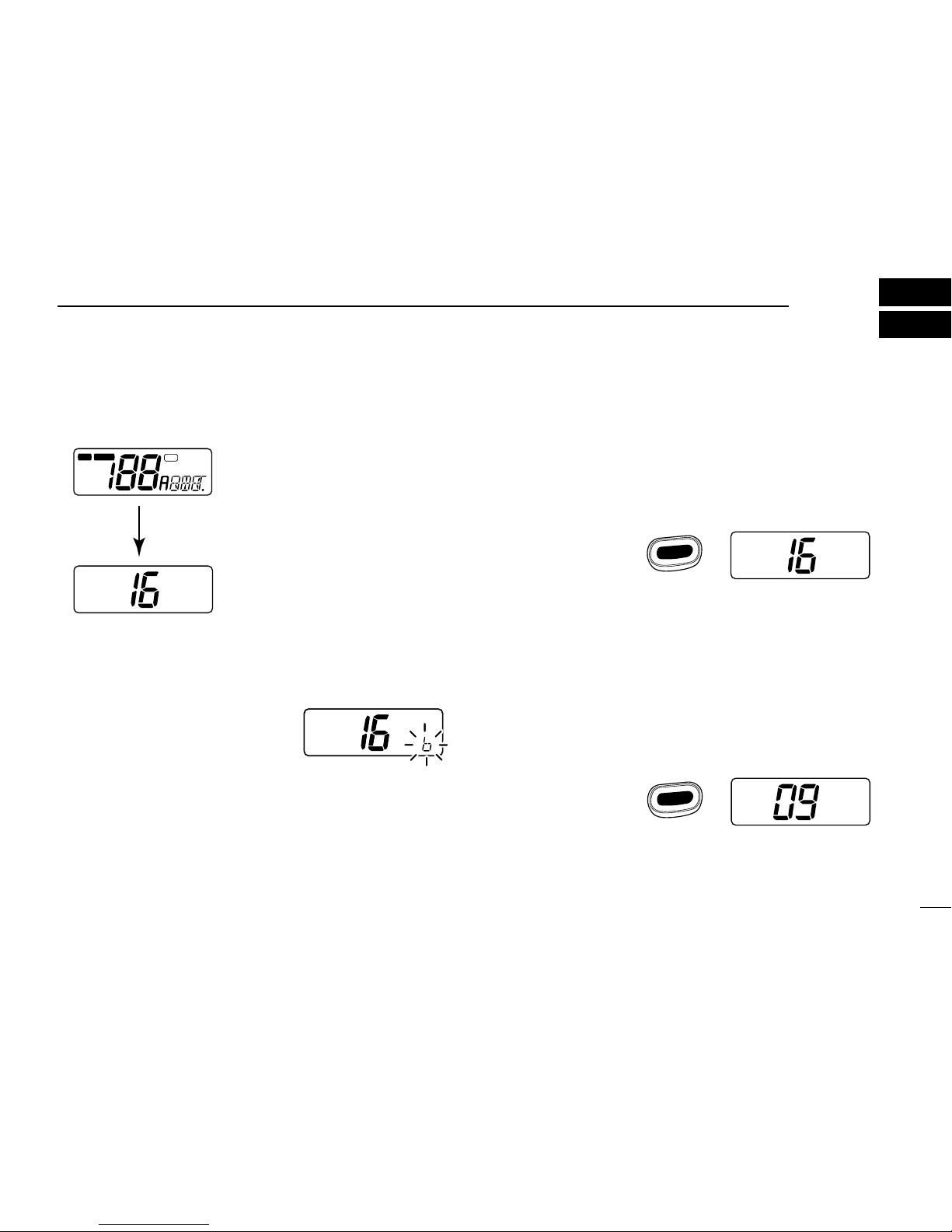
DLow voltage indicator
When “b” appears and flashes as
shown at right, there is a DC power
source problem. In this case, check
your vessel’s battery and DC power
cable.
USA
All display indications
appear briefly.
Channel 16 is automatically
selected.
LOW CALL
CANUSA
INT
ALTWX
TX
TAG
DUAL
SCAN
DUP ACK RCV
SCRM
TRI
BUSY
■Channel selection
DChannel 16
Channel 16 is the distress channel. It is used for establishing
initial contact with another station and for emergency com-
munications. Channel 16 is monitored during dual/tri-watch.
While standing by you are required to monitor channel 16.
DCall channel
The call channel is used to store your most often-used chan-
nel for quick recall. In addition, the call channel is monitored
during tri-watch. The default setting for the call channel is
channel 9 which is for leisure boat use. A separate call chan-
nel can be set for each channel group (USA, CAN and INT).
USA
USA
USA
Push
or hang the microphone
on the microphone hanger.
16
Push
for 1 sec. “CALL”indicates that the
call channel is selected.
16
9
CALL
USA
6
3BASIC OPERATION
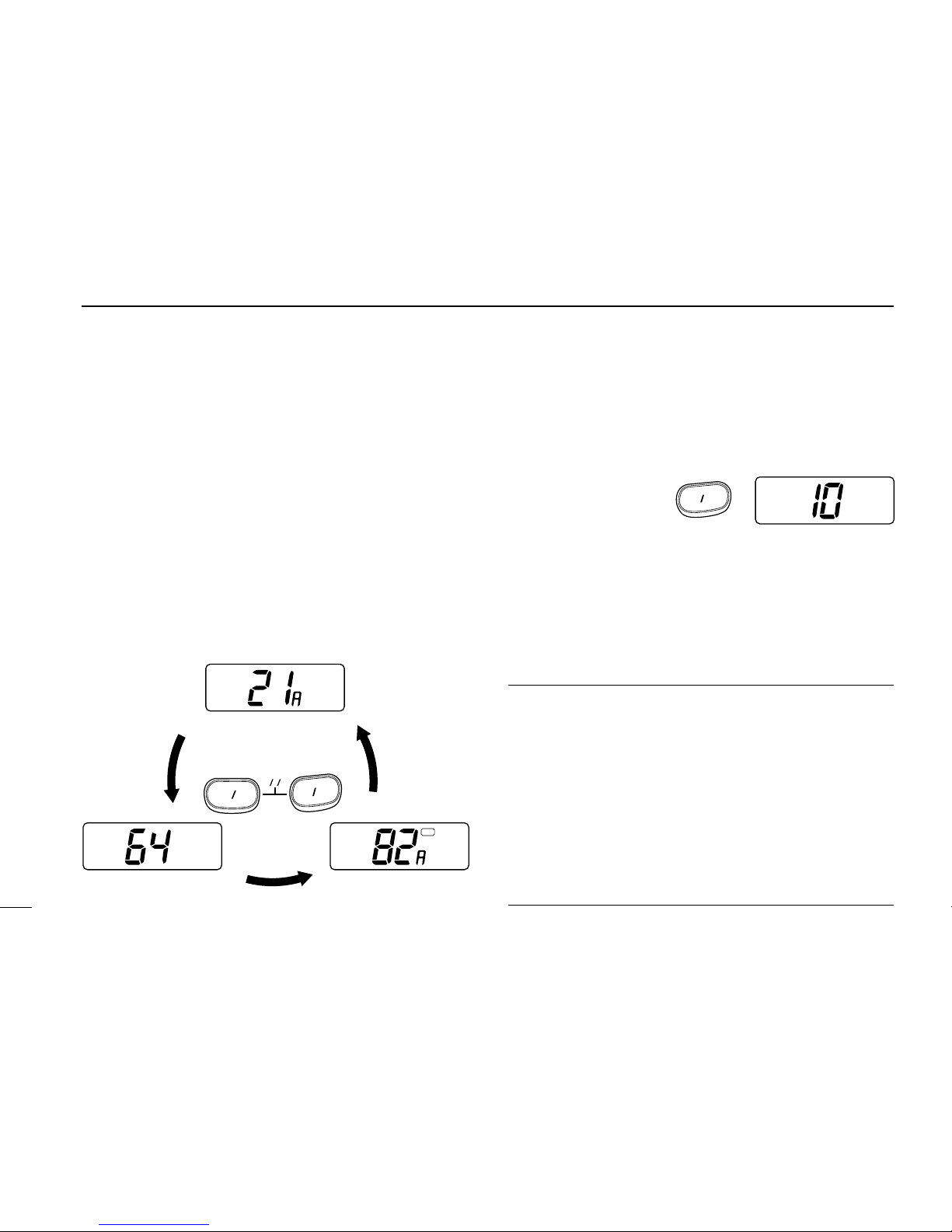
DUSA, Canadian and international channels
There are 57 USA, 57 Canadian and 57 international chan-
nels. These channel groups may be specified for the operat-
ing area.
➀Push [CH/WX] to select a regular channel.
•If regular channels (USA, CAN or INT) are already selected, this
step is not necessary.
➁Push [UP]/[DN] to select a channel.
•“DUP”appears for duplex channels.
➂To change the channel group, while push and hold [H/L]
push [CH/WX] simultaneously.
•USA, Canadian and international channels can be selected in se-
quence.
USA
INT
DUP
CAN
TAG
U.S.A. channels
Push simultaneously
International channels Canadian channels
CH WX
U
HL
IC
DWeather channels
There are 10 weather channels. These are used for monitor-
ing NOAA (National Oceanographic and Atmospheric Admin-
istration) weather broadcasts.
✔CONVENIENT
Weather alert function: NOAA broadcast stations transmit a
weather alert tone before important weather announcements.
•When the weather alert function is turned ON the “ALT”in-
dicator appears on the display.
•When the alert signal is received “ALT”flashes with an alert
tone and then weather announcements start.
This function is activated when a weather channel is selected
or during any scan. See “SET mode items”on p. 12.
Push
WX
CH WX
Table of contents
Other Icom Transceiver manuals

Icom
Icom D-STAR ID-31A; D-STAR ID-31E User manual

Icom
Icom IC-A14IC-A14S User manual

Icom
Icom IC-F14 User manual

Icom
Icom IC-2000 User manual

Icom
Icom IC-718 User manual

Icom
Icom iF3102D User manual

Icom
Icom IC-H16 User manual

Icom
Icom IC-E90 User manual

Icom
Icom IC-706MKIIG User manual

Icom
Icom IC-M402A User manual


