Icom IC-M710RT User manual

INSTRUCTION MANUAL
MF/HF MARINE TRANSCEIVER
iM710RT
IC-M710RT.qxd 02.1.9 9:03 Page A

ii
IMPORTANT
READ THIS INSTRUCTION MANUAL CAREFULLY
before attempting to operate the transceiver.
SAVE THIS INSTRUCTION MANUAL—This manual
contains important safety and operating instructions for
the IC-M710RT MF/HF MARINE TRANSCEIVER.
EXPLICIT DEFINITIONS
The explicit definitions described below apply to this
instruction manual.
☞NOTE: The IC-M710RTGMDSS version has a
high-stability crystal oscillator unit. This unit draws a
slight current even when power to the transceiver
is OFF. To prevent battery exhaustion when dock-
ing your vessel for extended periods, unplug the
DC cable from the DC power receptacle.
PRECAUTIONS
WORD DEFINITION
RWARNING Personal injury, fire hazard or electric
shock may occur.
CAUTION Equipment damage may occur.
NOTE If disregarded, inconvenience only. No risk
of personal injury, fire or electric shock.
RWARNING! NEVER connect the transceiver to an
AC outlet directly. This may pose a fire hazard or re-
sult in an electric shock.
RWARNING! NEVER mount the transceiver over-
head. The weight of the transceiver is approximately 8
kg., but its apparent weight will increase several fold
due to wave shocks and vibration. The transceiver
must be mounted on a flat hard surface only.
NEVER connect a power source of more than 16 V DC
such as a 24 volt battery. This connection will ruin the
transceiver.
NEVER place the transceiver where normal operation
of the ship or vehicle may be hindered or where it
could cause bodily injury.
Place unit in a secure place to avoid inadvertent use
by children.
NEVER expose the transceiver to rain, snow or any
liquids.
There are two types of grounding systems available for
the IC-M710RT—Negative Ground and Floating
Ground—NEVER install the negative ground type to a
plus-grounding ship. Such a connection might blow
fuses and is not usable.
DO NOT use chemical agents such as benzene or al-
cohol when cleaning, as they can damage the trans-
ceiver’s surfaces.
In maritime mobile operation, KEEP the transceiver
and microphone as far away as possible (at least 1 m)
from the magnetic navigation compass to prevent er-
roneous indications.
USE an Icom microphone and/or handset only (sup-
plied or optional). Other brands may have different pin
assignments and may damage the transceiver.
AVOID using or placing the transceiver in areas with
temperatures below –20°C (–4°F) or above +60°C
(+140°F).
AVOID connecting the transceiver to a power source
using reverse polarity. This connection will not only
blow fuses but may also damage the transceiver.
AVOID placing the transceiver in excessively dusty en-
vironments or in direct sunlight.
AVOID placing the transceiver against walls or putting
anything on top of the transceiver. This will obstruct
heat dissipation.
IC-M710RT.qxd 02.1.9 9:03 Page ii

iii
IN CASE OF EMERGENCY (for maritime operation)
VERSIONS
If your vessel requires assistance, contact other ves-
sels and the Coast Guard by sending a distress call on
2182 kHz.
Or, transmit your distress call using digital selective
calling on 2187.5 kHz.
The following versions are available for the
IC-M710RT:
❍USING 2182 kHz WITH VOICE
➀Push [2182kHz] to select the emergency fre-
quency.
➁Push [ALARM] and [TX FREQ] for 1 sec. to trans-
mit a 2-tone alarm signal for at least 30 sec.
• The transceiver automatically stops the alarm after 50
sec.
➂Push [ALARM] to turn the alarm transmission off,
then push and hold the PTT switch on the micro-
phone and send the following information:
1. “MAYDAY, MAYDAY, MAYDAY.”
2. “THIS IS . . . . . . . . . . . ” (name of vessel)
3. “LOCATED AT . . . . . . . ” (vessel’s position)
4. Give the reason for the distress call.
5. Explain what assistance you need.
6. Give additional information:
• Vessel type
• Vessel length
• Vessel color
• Number of people onboard.
❍USING DIGITAL SELECTIVE CALLING
(Only for GMDSS versions with an optional GM-
110DSC
DSC TERMINAL UNIT
)
When immediate help is needed
➀Push and hold [EMERGENCY] on the GM-
110DSC for 5 sec., until the short beeps become
one long beep, to send the distress call.
➁After 2182 kHz is automatically selected, transmit
the appropriate information as at left using voice.
When a potential problem exists
➀Push [SEL] on the GM-110DSC, then select “all
ships call” with [ENT] and the DATA SELECTOR.
➁Push and hold [CALL] on the GM-110DSC for 5
sec., until short beeps become one long beep, to
use the “all ships call” function.
➂After the pre-selected frequency is selected,
transmit the appropriate information using voice.
• DSC equipped ships may monitor your transmission.
Version
GMDSS
Marine
General
Ground type
Negative ground
and
Floating ground
Negative ground
and
Floating ground
Negative ground
only
Description
Corrosion-resistant exterior.
High stability crystal and FSK narrow filter built-in.
Optional DSC terminal unit can be connected.
2182 kHz 2-tone alarm is built-in.
FSK/CW narrow filter is optional.
All SSB/FSK ITU channels available.
2182 kHz 2-tone alarm is optional.
FSK/CW narrow filter is optional.
ITU channels are optional.
IC-M710RT.qxd 02.1.9 9:03 Page iii

iv
TABLE OF CONTENTS
IMPORTANT . . . . . . . . . . . . . . . . . . . . . . . . . . . . . . ii
EXPLICIT DEFINITIONS . . . . . . . . . . . . . . . . . . . . . ii
PRECAUTIONS . . . . . . . . . . . . . . . . . . . . . . . . . . . . ii
IN CASE OF EMERGENCY . . . . . . . . . . . . . . . . . . iii
VERSIONS . . . . . . . . . . . . . . . . . . . . . . . . . . . . . . . iii
TABLE OF CONTENTS . . . . . . . . . . . . . . . . . . . . . iv
1 OPERATING RULES AND GUIDELINES . . . . . . 1
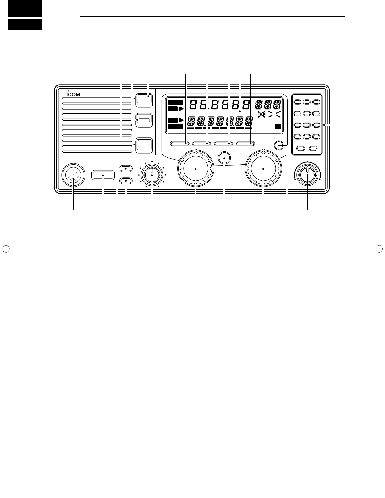
2 PANEL DESCRIPTION . . . . . . . . . . . . . . . . . . 2–5
■Front panel . . . . . . . . . . . . . . . . . . . . . . . . . . . . 2
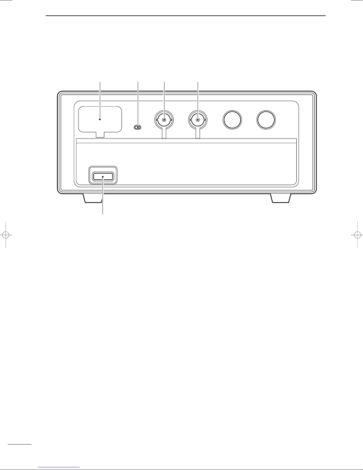
■Main unit . . . . . . . . . . . . . . . . . . . . . . . . . . . . . . 4
DHM-120 microphone keys . . . . . . . . . . . . . . . . . . . 4
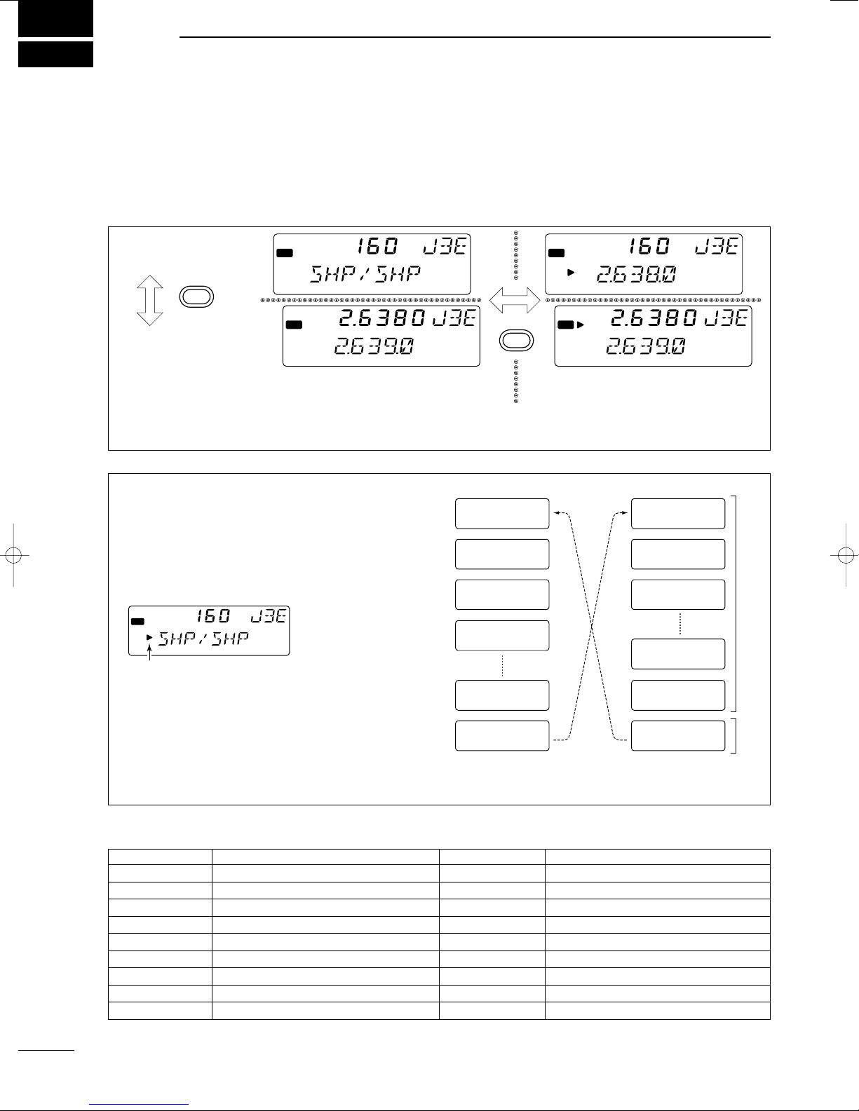
■Display . . . . . . . . . . . . . . . . . . . . . . . . . . . . . . . 5
3 SELECTING A CHANNEL/FREQUENCY . . . . 6–8
■Selecting a channel . . . . . . . . . . . . . . . . . . . . . 6
DUsing the channel selector . . . . . . . . . . . . . . . . . . 6
DUsing the keypad . . . . . . . . . . . . . . . . . . . . . . . . . . 7
DScan functions . . . . . . . . . . . . . . . . . . . . . . . . . . . . 7
■Selecting a frequency . . . . . . . . . . . . . . . . . . . . 8
DUsing the channel selector . . . . . . . . . . . . . . . . . . 8
DUsing the keypad . . . . . . . . . . . . . . . . . . . . . . . . . . 8
4 RECEIVE AND TRANSMIT . . . . . . . . . . . . . . 9–11
■Basic voice receive and transmit . . . . . . . . . . . 9
■Functions for transmit . . . . . . . . . . . . . . . . . . . . 9
DTransmit frequency check . . . . . . . . . . . . . . . . . . . 9
DTransmit power selection . . . . . . . . . . . . . . . . . . . . 9
■Functions for receive . . . . . . . . . . . . . . . . . . . 10
DSquelch function . . . . . . . . . . . . . . . . . . . . . . . . . 10
DNoise blanker . . . . . . . . . . . . . . . . . . . . . . . . . . . . 10
DAGC off function . . . . . . . . . . . . . . . . . . . . . . . . . . 10
DRF gain setting . . . . . . . . . . . . . . . . . . . . . . . . . . . 10
DClarity control . . . . . . . . . . . . . . . . . . . . . . . . . . . . 10
■CW operation . . . . . . . . . . . . . . . . . . . . . . . . . 11
■FSK operation . . . . . . . . . . . . . . . . . . . . . . . . . 11
■Cross channel operation . . . . . . . . . . . . . . . . . 11
5 USER CHANNEL PROGRAMMING . . . . . . . . . 12
■Programming a frequency . . . . . . . . . . . . . . . 12
DReceive frequency . . . . . . . . . . . . . . . . . . . . . . . . 12
DTransmit frequency . . . . . . . . . . . . . . . . . . . . . . . 12
DChannel names . . . . . . . . . . . . . . . . . . . . . . . . . . 12
6 SET MODE . . . . . . . . . . . . . . . . . . . . . . . . . . 12–15
■Set mode operation . . . . . . . . . . . . . . . . . . . . 12
■Set mode contents . . . . . . . . . . . . . . . . . . . . . 12
7 CONNECTIONS AND INSTALLATION . . . . 16–25
■Supplied accessories . . . . . . . . . . . . . . . . . . . 16
■Attaching 1 remote controller . . . . . . . . . . . . . 16
■Attaching 2 remote controllers . . . . . . . . . . . . 17
DSet ID number . . . . . . . . . . . . . . . . . . . . . . . . . . . 17
DIntercom operation . . . . . . . . . . . . . . . . . . . . . . . . 17
■Attaching 2 remote controllers and a PC . . . . 18
■Notes for remote control . . . . . . . . . . . . . . . . . 18
■Connections on rear panel . . . . . . . . . . . . . . . 19
■Connector information . . . . . . . . . . . . . . . . . . 20
■Ground connection . . . . . . . . . . . . . . . . . . . . . 22
■Power source . . . . . . . . . . . . . . . . . . . . . . . . . 22
■Antenna . . . . . . . . . . . . . . . . . . . . . . . . . . . . . 23
DMN-100/MN-101L . . . . . . . . . . . . . . . . . . . . . . . . 23
DAT-130 . . . . . . . . . . . . . . . . . . . . . . . . . . . . . . . . . 23
DNon-Icom tuner . . . . . . . . . . . . . . . . . . . . . . . . . . 23
■Mounting . . . . . . . . . . . . . . . . . . . . . . . . . . . . . 24
DMounting location . . . . . . . . . . . . . . . . . . . . . . . . . 24
DMounting example . . . . . . . . . . . . . . . . . . . . . . . . 24
DTransceiver dimensions . . . . . . . . . . . . . . . . . . . . 24
■Installing internal options . . . . . . . . . . . . . . . . 25
DOpening the case . . . . . . . . . . . . . . . . . . . . . . . . . 25
DInstalling an optional filter and alarm unit . . . . . . 25
■Fuse replacement . . . . . . . . . . . . . . . . . . . . . . 25
8 TROUBLESHOOTING . . . . . . . . . . . . . . . . . . . . 26
9 SPECIFICATIONS AND OPTIONS . . . . . . . . . . 27
■Specifications . . . . . . . . . . . . . . . . . . . . . . . . . 27
■Options . . . . . . . . . . . . . . . . . . . . . . . . . . . . . . 27
IC-M710RT.qxd 02.1.9 9:03 Page iv

1
1
OPERATING RULES AND GUIDELINES
❑CALL PROCEDURES
Calls must be properly identified and time limits must
be respected.
➀Give your call sign each time you call another vessel
or coast station. If you have no call sign, identify
your vessel name and the name of the licensee.
➁Give your call sign at the end of each transmission
that lasts more than 3 min.
➂You must break and give your call sign at least once
every 15 min. during long ship-to-shore calls.
➃Keep your unanswered calls short, less than 30 sec.
Do not repeat a call for 2 min.
➄Unnecessary transmissions are not allowed.
❑PRIORITIES
➀Read all rules and regulations pertaining to priorities
and keep an up-to-date copy handy. Safety and dis-
tress calls take priority over all others.
➁False or fraudulent distress calls are prohibited and
punishable by law.
❑PRIVACY
➀Information overheard but not intended for you can-
not be lawfully used in any way.
➁Indecent or profane language is prohibited.
❑LOGS
➀All distress, emergency and safety calls must be
recorded in complete detail. Log data activity is usu-
ally recorded in 24 hour time. Universal Time (UTC)
is frequently used.
➁Adjustments, repairs, channel frequency changes
and authorized modifications affecting electrical op-
eration of the equipment must be kept in the main-
tenance log; entries must be signed by the
authorized licensed technician performing or super-
vising the work.
❑RADIO LICENSES
(1) SHIP STATION LICENSE
You must have a current radio station license before
using the transceiver. It is unlawful to operate a ship
station which is not licensed.
Inquire through your dealer or the appropriate govern-
ment agency for a Ship-Radiotelephone license appli-
cation. This government-issued license states the call
sign which is your craft’s identification for radio pur-
poses.
(2) OPERATOR’S LICENSE
A Restricted Radiotelephone Operator Permit is the li-
cense most often held by small vessel radio operators
when a radio is not required for safety purposes.
The Restricted Radiotelephone Operator Permit must
be posted or be kept with the operator. Only a licensed
radio operator may operate a transceiver.
However, non-licensed individuals may talk over a
transceiver if a licensed operator starts, supervises,
and ends the call, and makes the necessary log en-
tries.
Keep a copy of the current government rules and reg-
ulations handy.
IC-M710RT.qxd 02.1.9 9:03 Page 1

2
2PANEL DESCRIPTION
■Front panel (controller)
qMICROPHONE CONNECTOR (p. 20)
Accepts the supplied microphone or an optional
handset.
☞NOTE: No audio is output via the speaker when the
microphone or handset is not connected.
wPOWER SWITCH [POWER]
Turns power on and off.
eSPEAKER SWITCH [SPEAKER]
Turns the built-in speaker on and off.
•“è” appears in the display while the speaker is turned
off.
• Any external speaker connected to the rear panel is not
turned off.
rDISPLAY INTENSITY SWITCH [DIMMER]
➥Toggles the display backlight on and off.
➥While pushing, rotate [CHANNEL] to adjust the
backlighting to one of 4 levels.
➥While pushing, rotate [GROUP] to adjust the dis-
play contrast to one of 10 levels.
tVOLUME CONTROL [VOLUME]
Adjusts the audio output level.
• Audio does not come from the speaker when:
➟A microphone is not connected.
➟The [SQL] switch is turned on and no signal is being
received.
yGROUP CHANNEL SELECTOR [GROUP]
Selects groups in 20 channel steps and ITU marine
channel groups.
☞NOTE: Some versions have no ITU channels.
uANTENNA TUNE SWITCH [TUNE] (p. 9)
Tunes the connected tuner to the antenna.
• Activates only when an optional antenna tuner such as
Icom’s AT-130/E is connected.
☞NOTE: When selecting “automatic tuning” in set
mode, pushing this switch is not necessary to tune
the antenna. (p. 13)
iCHANNEL SELECTOR [CHANNEL] (p. 6)
➥Selects an operating channel within the selected
channel group such as ITU channels.
• User channels can be selected from 1 to 160 (max.)
in sequence regardless of the channel group.
➥Changes the operating frequency* after [CE] is
pushed (while “s” appears).
• The changed frequency is not programmed in this
way.
oFUNCTION SWITCH [FUNC]
After pushing, activates the secondary functions of
these switches:
[RESET] . . Deactivates external control such as
from a DSC terminal unit when con-
nected.
[SQL] . . . . . Starts and stops scan (p. 7).
[SPEAKER] Activates intercom function (p. 17).
[RX] . . . . . . Sets RF gain (p. 10).
[TX] . . . . . . Selects transmit power (p. 9).
[CE] . . . . . . Reprograms the channel name (p.
12).
☞NOTE: Function availability depends on version.
!0 CLARITY CONTROL [CLARITY] (p. 10)
Shifts the receive frequency ±150 Hz for clear re-
ception of an off frequency signal.
TUNE DUP SIMP STANDBY
TX
RX
DSC FSCAN
SQL N B
AGC
AGC
A43210
ALM
MICROPHONE
POWER
VOLUME
ALARM
TX FREQ
2182KHz
RESET
MODE
TUNE
MF/HF MARINE TRANSCEIVER
AGC SQL FUNC
CLARITY
NB
SPEAKER
[ALARM] [TX FREQ]+
FOR ALARM TX
DIMMER
GROUP CHANNEL
123
456
789
CE
RX TX
0–
CH/FREQ
iM 710
q w e r t y u i !0
!1
o
!2!3!4!5 !6!7!8!9
IC-M710RT.qxd 02.1.9 9:03 Page 2

3
2
PANEL DESCRIPTION
!1 KEYPAD
➥Enters the selected channel number (or fre-
quency*) for direct channel selection. (p. 7)
➥Stores a receive frequency into a user chan-
nel or ITU simplex channel when:
•pushing [CE] (“s”appears)
•entering the desired frequency via the keypad
•pushing and holding [RX] (p. 12)
➥Adjusts the RF gain after pushing [FUNC] to
reduce the receiver sensitivity. (p. 10)
➥Stores a transmit frequency into a user chan-
nel (except General versions) when:
•pushing [TX] (“$”flashes)
•pushing [CE] (“s”appears)
•entering the desired frequency via the keypad
•pushing and holding [TX] (p. 12)
➥Selects the transmitter channel for cross
channel operation (Europe versions only)
when:
•pushing [TX] (“$”flashes)
•entering the desired channel number via the key-
pad
➥Selects the transmit output power after push-
ing [FUNC]. (p. 9)
➥Toggles the channel number input and fre-
quency input.* (p. 8)
•“s”appears when frequency input* is selected.
•The channel selector and keypad changes the
frequency while “s”appears.
➥Clears the entered digit and retrieves the pre-
vious channel (or frequency*) while entering
numbers. (p. 7)
➥Enters the name programming condition,
after pushing [FUNC], for changing the chan-
nel name. (p. 12)
➥Toggles the channel and frequency indica-
tions. (p. 6)
➥Enters “–” for ITU simplex channels. (p. 7)
➥Enter channel number with up to 4 or 5 digits
when “s”does not appear. (p. 7)
➥Enter the frequency with up to 6 digits* when
“” appears. (p. 8)
!2 SQUELCH SWITCH [SQL] (p. 10)
➥Activates the voice squelch function to reject un-
desired background noise while no signal is
being received.
•The squelch opens only when the received signal
contains no voice or FSK components.
➥Starts and stops the scan function after pushing
[FUNC]. (p. 7)
!3 NOISE BLANKER SWITCH [NB] (p. 10)
Turns the noise blanker function on to remove
pulse-type noise such as engine ignition noise.
•“NB”appears when the function is turned on.
0
9
to
–
CH/FREQ
CE
TX
RX
!4 AGC OFF SWITCH [AGC] (p. 10)
Deactivates the AGC function to receive weak sig-
nals blocked by strong adjacent signals.
•“ê”appears when the [AGC] switch is turned on
(stands for AGC deactivated).
!5 MODE SWITCH [MODE] (p. 9)
Selects an operating mode temporarily. Available
modes differ with version.
•J3E (USB), H3E, J2B (AFSK), FSK, R3E and A1A (CW)
modes are available.
•The temporary mode is cleared and the previous mode
appears when changing a channel.
!6 OVEN INDICATOR (GMDSS version only)
Internal high-stability crystal oscillator unit contains
a temperature-compensating oven heater. This
high-stability crystal oscillator improves frequency
stability.
•“STANDBY”appears when power to the main unit is
turned off.
!7 TRANSMIT FREQUENCY SWITCH [TX FREQ]
(p. 9)
Displays the transmit frequency and opens the
squelch to check and monitor the transmit fre-
quency.
!8 2182 kHz SELECTION SWITCH
[2182kHz •
RESET
] (p. iii)
➥Selects channel 0 (2182 kHz; distress call fre-
quency).
•The channel selector does not function when select-
ing channel 0.
➥Ignores external control and gives the front panel
control priority when an external controller
(NMEA format) is connected.
!9 ALARM SWITCH [ALARM] (p. iii)
➥Emits a distress alarm signal from the speaker.
➥Transmits a distress alarm or alarm testing signal
when pushed together with the [TX FREQ]
switch.
☞NOTE: General versions are not equipped with this
[ALARM] switch.
*Some versions do not have frequency selection and fre-
quency indication.
IC-M710RT.qxd 02.1.9 9:03 Page 3

qRS-232C CONNECTOR (p. 18)
Connects the IC-M710RT to a PC via an RS-232C
cable for remote control of transceiver function
using the optional RS-710RT software.
wPOWER INDICATOR
Appears while power is turned on.
eCONTROLLER CONNECTOR
Connects the main body of the IC-M710RT to the
front panel (controller) when detached from the
main body.
rCONTROLLER CONNECTOR (pgs. 16, 17)
Same as above.
tPOWER SWITCH
Same function as the power switch ([POWER]) on
the front panel.
•Only available on the Europe and GMDSS versions.
4
2PANEL DESCRIPTION
q
t
wer
■Main unit (controller detached)
DHM-120 microphone keys
The “P”key on the HM-120
HAND MICROPHONE
can be
set to function as the [MODE], [NB], [AGC], [SQL] or
[TUNE] keys on the remote controller. (The YZ keys
function the same as the [CHANNEL] selector). Also,
using set mode (p. 15) these keys can be deactivated
if desired.
While pushing [P] on the microphone and the switch
on the remote controller whose function you want to
assign (see above), turn power ON.
•Repeat this to assign a different key.
IC-M710RT.qxd 02.1.9 9:03 Page 4

5
2
PANEL DESCRIPTION
■Display
qALARM INDICATOR (p. iii)
Appears when the alarm function is activated such
as for an alarm test or distress alarm transmission.
•Not available in General version.
wRECEIVE INDICATOR (p. 10)
Appears while receiving and when the squelch is
open.
eTUNE INDICATOR (p. 9)
Flashes while the connected antenna tuner, such as
Icom’s AT-130, is being tuned.
•Tuning starts when transmitting on a new frequency or
pushing the [TUNE] switch.
rTRANSMIT INDICATOR
➥Appears when transmitting. (p. 9)
➥Flashes when the [TX] key is pushed for transmit
frequency programming. (p. 12)
tDSC INDICATOR (p. iii)
Appears when an optional GM-110DSC
DSC TERMI
-
NAL UNIT
controls transceiver functions.
•The GM-110DSC can be connected to GMDSS versions
only.
yS/RF METER
➥Shows the relative received signal strength while
receiving.
➥Shows output power while transmitting.
➥Shows antenna current level when an optional
AT-130E
HF ANTENNA TUNER
is connected (Europe
versions only).
uCHANNEL/VFO INDICATOR
➥Shows the pre-programmed channel name (al-
phanumeric) during channel indication. (p. 6)
•Some versions have no channel name function and
show receive frequency instead.
➥Shows the transmit frequency during frequency
indication. (p. 6)
➥Shows transmit channel number during cross
channel operation (Europe versions only). (p. 11)
TUNE DUP SIMP
TX
RX
DSC FSCAN
SQL N B
AGC
AGC
A43210
ALM
q
w
e
r
t
yu io!0
!1
!2
!3!4!5!6!7
iSQUELCH INDICATOR (p. 10)
Appears when the squelch is on.
oSCAN INDICATOR (p. 7)
Appears when the scan function is in use.
•The scan function is not available on some versions.
•Pushing [FUNC] then [SQL] starts and stops scan.
!0 FUNCTION INDICATOR
Appears when the [FUNC] switch is pushed.
!1 NOISE BLANKER INDICATOR (p. 10)
Appears when the [NB] switch is turned on.
!2 AGC OFF INDICATOR (p. 10)
Appears when the [AGC] switch is pushed to indi-
cate the AGC function is deactivated.
!3 MODE READOUT
Shows the selected operating mode (type of emis-
sion).
!4 SPEAKER OFF INDICATOR
Appears when the [SPEAKER] switch is pushed to
indicate the front panel speaker is deactivated.
!5 CHANNEL READOUT
➥Shows the selected channel number during
channel indication. (p. 6)
➥Shows the receive frequency during frequency in-
dication. (p. 9)
!6 SIMPLEX/DUPLEX INDICATORS
These appear to show whether the selected chan-
nel is simplex or duplex.
!7 FREQUENCY INDICATORS (p. 8)
Appear when the frequency entry condition* is se-
lected for frequency selection.
•The [CE] key toggles the indicator ON and OFF.
* Some versions have no frequency entry condition.
IC-M710RT.qxd 02.1.9 9:03 Page 5

6
3SELECTING A CHANNEL/FREQUENCY
■Selecting a channel
The transceiver has 160 user channels and ITU chan-
nels. However, the number of user channels can be
optionally restricted and ITU channels are not available
with some versions.
☞NOTE: When channel 0 and/or 2182 kHz is se-
lected with the [2182KHz] switch, channel selection
is NOT possible. In such cases, push [2182KHz] in
advance.
DUP
TX
RX
DSC F
AGC
ALM
DUP
TX
RX
DSC F
AGC
ALM
DUP
TX
RX
DSC F
AGC
ALM
DUP
TX
RX
DSC F
AGC
ALM
CHANNEL INDICATION
FREQUENCY INDICATION
CHANNEL SELECTION MODE
Channel can be selected
FREQUENCY SELECTION MODE
Frequency can be changed
CH/FREQ
CE
DUsing the channel selector
The transceiver has two large controls for group se-
lection and channel selection. The [GROUP] selector
changes channels in 20 channel increments and se-
lects ITU channel groups*; and the [CHANNEL] se-
lector selects each channel.
➀Make sure no “s”indicator appears on the display.
➁Rotate the [GROUP] selector to select the desired
channel group as shown at right and/or below.
➂Rotate the [CHANNEL] selector to select the de-
sired channel.
[EXAMPLE]: Selection with the [GROUP] selector
*All ITU channels are not available with some versions and ITU
FSK channels can be hidden using set mode. (p. 13)
1 J3E
WWV
21 J3E
KMI
41 J3E
WOM
61 J3E
WOO
121 J3E
FAX
141 J3E
SHP/SHP
401 J3E
4.357.0
4-1 J3E
4A LTD
601 J3E
6.501.0
2501 J3E
26.145.0
25-1 J3E
FAX
4001 FSK
4.210.5
ITU FSK
channels*
ITU SSB channels*
DUP
TX
RX
DSC F
AGC
ALM
If appears, push [CE] to delete it.
☞NOTE: Channel name (alphanumeric) may not
appear during channel indication depending on
set mode settings (p. 14).
CHANNEL GROUPS
CHANNEL NO. DESCRIPTION
1 to 160 User channels*1
401 to 427 4 MHz ITU duplex channels
4-1 to 4-9 4 MHz ITU simplex channels
601 to 608 6 MHz ITU duplex channels
6-1 to 6-9 6 MHz ITU simplex channels
801 to 832 8 MHz ITU duplex channels
8-1 to 8-9 8 MHz ITU simplex channels
1201 to 1241 12 MHz ITU duplex channels
12-1 to 12-9 12 MHz ITU simplex channels
CHANNEL NO. DESCRIPTION
1601to 1656 16 MHz ITU duplex channels
16-1 to 16-9 16 MHz ITU simplex channels
1801 to 1815 18 MHz ITU duplex channels
18-1 to 18-9 18 MHz ITU simplex channels
2201 to 2253 22 MHz ITU duplex channels
22-1 to 22-9 22 MHz ITU simplex channels
2501 to 2510 25 MHz ITU duplex channels
25-1 to 25-9 25 MHz ITU simplex channels
4001 to 25040 ITU FSK duplex channels*2
*1[GROUP] selector changes in 20 channels steps.
*2SITOR use—no group separation.
IC-M710RT.qxd 02.1.9 9:03 Page 6

7
3
SELECTING A CHANNEL/FREQUENCY
DUsing scan functions
(Some versions do not have these functions)
The transceiver has automatic channel or frequency
change capability (scan function). There are 3 types
of scan functions available to suit your needs.
Channel scan and channel resume scan increase
channels within a 5 channel range such as ch 1 to ch
5, ch 156 to ch 160, etc. in user channels; or all chan-
nels in the group of ITU channels.
Programmed scan (optional) changes frequencies
within the frequency range between user channels
159 and 160.
Scan selection is available in set mode. See p. 14 for
scan selection.
SCAN OPERATION
➀Select your desired channel group with the
[GROUP] and [CHANNEL] selector.
•Or use the keypad and [CE] key for direct selection.
•This operation is not necessary for programmed scan.
➁Push [SQL] to turn OFF the squelch function if pro-
grammed scan is selected.
➂Push [FUNC] then [SQL] to start the scan.
➃To stop the scan, repeat step ➂again.
•[CHANNEL] rotation and some other switches also stop
the scan.
Channel scan
ch 1
ch 2 ch 3
ch 4
ch 5
scan is
cancelled
when
transmitting
Channel resume scan
ch 1
ch 2 ch 3
ch 4
ch 5
scan pauses
for 30 sec.,
then resumes
after
transmitting
DUsing the keypad
Direct channel selection via the keypad is available
for quick channel selection.
➀Make sure “s”does not appear on the display.
•If it appears, push [CE] to delete it.
➁Enter the desired channel number via the keypad.
•A user channel is selected when channel 1–160 is input
(max. number may be optionally restricted).
•An ITU SSB channel is selected when channel num-
bers higher than 401 are input (not available for some
versions).
•An ITU FSK channel is selected when channel numbers
higher than 4001 are input (not usable according to set
mode setting).
•The “–” key can be used for selecting an ITU simplex
channel.
➂Push [RX] to select the entered channel.
[EXAMPLE]: Selecting channel 153
DUP
TX
RX
DSC F
AGC
ALM
DUP
TX
RX
DSC F
AGC
ALM
DUP
TX
RX
DSC F
AGC
ALM
DUP
TX
RX
DSC F
AGC
ALM
DUP
TX
RX
DSC F
AGC
ALM
1
5
3
RX
Programmed scan (optional)
ch 159 ch 160
Scans the frequency range
between the programmed
frqeuencies on channels
159 and 160.
Scans fast when squelch is
closed and slowly when
squelch is open.
IC-M710RT.qxd 02.1.9 9:03 Page 7

8
3SELECTING A CHANNEL/FREQUENCY
■Selecting a frequency
The transceiver has 0.5 to 30.0 MHz general coverage
receive capability with 100 Hz resolution. The receive
frequency can be changed instantly, independent of
the transmit frequency.
☞NOTE: The selected frequency is used for tempo-
rary receiving (transmitting is not available). This
frequency is cleared once the channel is changed.
If you want to program a frequency, refer to p. 12.
DUsing the keypad
☞CAUTION: A frequency can be entered into a
user channel or ITU simplex channel by pushing
the [RX] key. However, when pushing and hold-
ing the [RX] key after entering a frequency, the
previously programmed contents are erased and
cannot be retrieved. Therefore, keypad entry
should be used only on spare channels.
➀Select the memory channel to be used for general
coverage use.
➁Push [CE] to select frequency selection mode.
➂Enter the desired frequency with 5 or 6 digits.
➃Push [RX] to input the frequency.
•Do not hold [RX] for more than 0.5 sec., otherwise the
frequency will be programmed into the channel.
[EXAMPLE]: Setting 12.3450 MHz
DUsing the channel selector
➀Select a channel which is programmed near the
frequency you want to receive.
➁Push the [CE] key to select frequency selection
mode.
•“s”appears on the display.
➂Rotate the [CHANNEL] selector to change the fre-
quency.
➃To return to the previous frequency, push [CE].
•“s”disappears and the previous frequency or channel
name appears.
TX
RX
DSC F
AGC
ALM
No frqeuency programmed channel for general
coverage use.
(mode and channel name do not appear)
DUP
TX
RX
DSC F
AGC
ALM
DUP
TX
RX
DSC F
AGC
ALM
No “≈”indicator shows that the channel will
be changed when rotating [CHANNEL].
“≈”and frequency show that the frequency
will be changed.
CE
TX
RX
DSC F
AGC
ALM
TX
RX
DSC F
AGC
ALM
TX
RX
DSC F
AGC
ALM
TX
RX
DSC F
AGC
ALM
TX
RX
DSC F
AGC
ALM
TX
RX
DSC F
AGC
ALM
TX
RX
DSC F
AGC
ALM
Select non frqeuency
programmed channel.
After temporarily receiving.
1
5
3
RX
2
4
0
CE
CE
(momentarily)
IC-M710RT.qxd 02.1.9 9:03 Page 8

4
RECEIVE AND TRANSMIT
9
■Basic voice receive and transmit
➀Check the following in advance:
➥Microphone is connected.
➥[SPEAKER] switch is turned off.
➥[SQL] switch is turned off.
➥[CLARITY] control is set to the center position.
➁Select the desired channel to be received with the
[GROUP] and [CHANNEL] selectors.
•When receiving a signal, the S-meter shows the signal
strength.
➂Adjust [VOLUME] to the desired audio level when
receiving a signal.
➃Push [MODE] to select the desired operating mode,
if the received signal is in a different mode.
➄Push [TUNE] to tune the antenna tuner, if con-
nected.
•This operation is not necessary when “automatic tuning”
is selected in set mode (p. 13).
➅To transmit on the channel, push and hold the PTT
switch on the microphone.
•“TUNE”flashes for 1 to 2 sec. for the first transmission
on a channel when an antenna tuner is connected.
➆After the flashing stops, speak into the microphone
at your normal voice level.
•The RF meter shows the output power according to your
voice level.
➇Release the PTT switch to return to receive.
microphone
connector
[SQL]
[SPEAKER] [CLARITY]
■Functions for transmit
DTransmit frequency check
When “DUP”appears on the display such as for a
ship-to-shore channel, the transmit frequency differs
from the receive frequency.
In such cases, the transmit frequency should be mon-
itored before transmitting to prevent interference to
other stations.
Push and hold [TX FREQ] to monitor the transmit fre-
quency.
•The display shows the transmit frequency.
TX FREQ
DTransmit power selection
The transceiver has 3 selectable output powers.*
High power allows longer distance communications
and low power reduces power consumption.
*Only 2 selectable output powers are available with some
versions. In this case, level 1 stands for 60 W (the same as
level 2).
☞NOTE: Low power setting affects all channels ex-
cept the 2182 kHz emergency channel.
☞NOTE: Although power selection appears possi-
ble with GMDSS versions, only high power is
available.
➀Push [FUNC] then [TX] to call up the following dis-
play.
➁Rotate the [CHANNEL] selector to select high or
low output power.
3 : high power (150 W PEP)
2 : middle power (60 W PEP)
1 : low power (20 W PEP)
➂Push [FUNC] or [CE] to return to the previous dis-
play.
TX
RX
DSC F
AGC
ALM
IC-M710RT.qxd 02.1.9 9:03 Page 9

10
4RECEIVE AND TRANSMIT
■Functions for receive
DSquelch function
The squelch function detects signals with voice com-
ponents and squelches (mutes) unwanted signals
such as unmodulated beat signals. This provides
quiet standby.
When you need to receive weak signals, the squelch
should be turned off.
Push [SQL] to toggle the function on and off.
•“SQL”appears when the squelch function is turned on.
DUP
TX
RX
DSC F
SQL
AGC
ALM
DNoise blanker
The noise blanker function reduces pulse type noise
such as that coming from engine ignitions.
The noise blanker may distort reception of strong sig-
nals. In such cases, the noise blanker should be
turned off.
Push [NB] to toggle the function on and off.
•“NB”appears when the noise blanker function is turned
on.
DUP
TX
RX
DSC F
NB
AGC
ALM
DAGC off function
The receiver gain is automatically adjusted according
to received signal strength with the AGC (Automatic
Gain Control) function to prevent distortion from
strong signals and to obtain a constant output level.
When receiving weak signals with adjacent strong
signals or noise, the AGC function may reduce the
sensitivity. In this situation, the AGC function should
be deactivated.
Push [AGC] to toggle the function on and off.
•“ê”appears when the AGC function is deactivated.
TX
RX
DSC F
AGC
AG
AG
C
ALM
DRF gain setting
The receiver gain can be reduced with the RF gain
setting. This may help to remove undesired weak sig-
nals while monitoring strong signals.
Usually, the AGC function reduces the RF gain ac-
cording to the receive signal strength and these weak
signals are remove. However, during no signal recep-
tion, these weak signals may not be heard.
In such cases, the RF gain may be useful for setting a
minimum level at which to hear signals.
➀Push [FUNC] then [RX] to call up the following dis-
play.
➁Rotate the [CHANNEL] selector to set the desired
minimum cutting level.
•“0”to “9”are available.
•S-meter shows the minimum permitted level.
➂Push [FUNC] or [CE] to exit the RF gain display.
TX
RX
DSC F
AGC
ALM
DClarity control
Voice signals received from other stations may be dif-
ficult to receive. This may sometimes happen if a sta-
tion is transmitting slightly off frequency. In such
cases, compensate the receive frequency only, using
the [CLARITY] control.
Adjust [CLARITY] to improve the audio signal.
[CLARITY]
IC-M710RT.qxd 02.1.9 9:03 Page 10

11
4
RECEIVE AND TRANSMIT
■CW operation
The transceiver has the following CW keying features
selectable in set mode as described on page 15.
➥Full break-in (receiving is possible while transmitting)
➥Delay keying (automatic transmission with keying)
➥Off (manual transmission is necessary before keying)
➀Connect a CW keyer or an external electronic
keyer to the ACC(1) socket as shown at right.
➁Select the desired channel to operate CW mode.
➂When the selected channel is not in A1A mode,
push [MODE] one or more times to select “A1A.”
➃Operate the CW keyer to transmit a CW signal.
☞NOTE: CW mode is not available in some ver-
sions and CW narrow can be selected in set mode
(p. 14) when an optional filter is installed (already
built-in to the GMDSS versions).
CW key connection
2
8
45
13
67
ACC(1) socket
pin 1
pin 2
CW key
■FSK operation
The transceiver has FSK and J2B modes for FSK op-
eration—use FSK when using the built-in oscillator;
use J2B when using an AFSK terminal unit.
➀Connect an FSK terminal unit as shown at right.
➁Select the desired channel.
•FSK ITU channel group, ch 4001 to ch 25040, are avail-
able depending on version.
➂Push [MODE] one or more times to select the type
of emission, “FSK”or “J2B.”
➃Operate the FSK terminal unit.
☞NOTE:
➥FSK shift frequency and FSK polarity can be
adjusted in set mode (p. 14).
➥Some transceivers my operate 1.7 kHz higher
than the IC-M710RT’s J2B mode even when
the same displayed frequencies are in use.
FSK terminal unit connection
2
8
45
13
67
ACC(1) socket
FSK terminal unit
FSK keying
AF input
Tx/Rx control
Ground
pin 3
pin 4
pins 2, 5
■Cross channel operation*
Cross channel operation is available with some ver-
sions to operate different channels for receive and
transmit.
➀Select the desired channel for receive.
•ITU simplex channels cannot be used.
➁Push [TX], then select the desired channel for
transmit.
•“$”flashes after pushing [TX].
➂Push [TX] again to stop the blinking.
➃Operate the transceiver normally.
➄Change the channel to clear the cross channel set-
ting.
*This function is available for Europe versions only.
Cross channel operation example
DUP
TX
RX
DSC F
AGC
A43210
ALM
DUP
TX
RX
DSC F
AGC
A43210
ALM
While receiving
While transmitting
IC-M710RT.qxd 02.1.9 9:03 Page 11

12
5USER CHANNEL PROGRAMMING
■Programming a frequency
The IC-M710RT has up to 160 user-programmable
channels each with channel name capability of up to 7
alphanumeric characters.
☞NOTE: ITU simplex channels can be programmed
as well as user channels. However, transmit fre-
quencies cannot be programmed as it is not neces-
sary.
DReceive frequency
➀Select the desired channel to be programmed.
•Channels 1 to 160 (maximum) are programmable.
➁Push [CE] to select frequency selection mode.
•“s”and frequency appear on the display.
➂Enter the desired frequency via the keypad—5 or
6 digits.
•Or rotate the [CHANNEL] selector to change the fre-
quency.
➃To change the operating mode (type of emission),
push [MODE] one or more times.
➄Push and hold [RX] for 1 sec. to program the user
channel.
DTransmit frequency
(Not applicable for General versions)
➀Select the desired user channel to be programmed.
➁Push [TX].
•“$”flashes.
➂Push [CE] to select frequency selection mode.
•“s”and frequency appear on the display.
➃Enter the desired frequency via the keypad with 5
or 6 digits.
•The [CHANNEL] selector cannot be used.
➄Push and hold [TX] for 1 sec. to program.
➅Push [TX] to stop “$”from flashing.
DChannel names
➀Select the desired user channel to be programmed.
➁Push [CH/FREQ] to select channel indication.
➂Push [FUNC] then [CE].
•The channel name (alphanumeric) readout flashes.
➃Rotate the [GROUP] selector for cursor position
and the [CHANNEL] selector for name content.
•To return to the previous message, push [CE].
➄Push and hold [RX] to program the name.
•Flashing stops.
DUP
TX
RX
DSC F
AGC
ALM
DUP
TX
RX
DSC F
AGC
ALM
DUP
TX
RX
DSC F
AGC
ALM
Push [CE]
Frequency and “≈”appear.
Set frequency
Use keypad or channel selector.
Push and hold [RX]
Programming is completed.
DUP
TX
RX
DSC F
AGC
ALM
DUP
TX
RX
DSC F
AGC
ALM
DUP
TX
RX
DSC F
AGC
ALM
Push [TX]
“$”flashes.
Push [CE]
Push and hold [TX]
after entering a
frqeuency
DUP
TX
RX
DSC F
AGC
ALM
DUP
TX
RX
DSC F
AGC
ALM
DUP
TX
RX
DSC F
AGC
ALM
Push [FUNC]
then [CE]
“$”flashes.
Rotate [GROUP]
and [CHANNEL]
to select cursor and
character
Push [RX]
IC-M710RT.qxd 02.1.9 9:03 Page 12

13
6
SET MODE
■Set mode operation
Set mode operation is used for programming infre-
quently changed values or conditions of functions.
✍NOTE: Some of the set mode items described in
this section are not available on some transceiver
versions.
➀Push [POWER] to turn power off, if necessary.
➁While pushing [FUNC] + [1], push [POWER] to turn
power on and enter set mode.
➂Rotate the [GROUP] selector to select the desired
item.
➃Rotate the [CHANNEL] selector to set the values or
conditions for the selected item.
➄Turn power off and on again to exit set mode.
TX
RX
DSC F
AGC
ALM
[POWER] [FUNC] [1]
Condition
Item
■Set mode contents
(2) Connected antenna tuner
The transceiver has several tuner control systems for
use with an optional Icom antenna tuner. Select the
condition depending on the connected antenna tuner.
☞NOTE: Internal switch selection may be required
when using a non-Icom tuner (p. 23).
AT-130
(default)
AT-120
AH-3
(3) Automatic tuning condition
When the optional AT-130 or AT-130E automatic an-
tenna tuner is connected, tuning can be started auto-
matically without the [TUNE] switch, for instant
operation.
If manual tuning is required, this automatic operation
can be deactivated.
Tuning starts when pushing
[PTT] on a new frqeuency.
Tuning starts only when
[TUNE] is pushed.
(default)
TX
RX
DSC F
AGC
ALM
TX
RX
DSC F
AGC
ALM
(1) FSK ITU channels
FSK ITU channels appear as a group between the
ITU 25 MHz band and user channels. This FSK chan-
nel group can be hidden for voice communication
only.
FSK channels don’t appear
(no SITOR operation).
(default)
FSK channels appear (for
SITOR operation).
IC-M710RT.qxd 02.1.9 9:03 Page 13

14
6SET MODE
(5) Scan speed
This item adjusts the scan speed (rate at which chan-
nels are searched). The scan speed can be set from
1 to 10 with “1”being the fastest and “10”being the
slowest.
Fastest scan speed
Slowest scan speed
(default: 4)
TX
RX
DSC F
AGC
ALM
TX
RX
DSC F
AGC
ALM
(6) Channel name and frequency
The lower half of the display can be set to display a
programmable channel name or a receive frequency
according to operator needs.
Channel number
and channel name
—alphanumeric
(default)
Channel number
and frequency
(7) CW/FSK narrow filter
This item selects the passband width for A1A (CW),
FSK or J2B mode.
✍NOTE: When “on”is selected without optional fil-
ter installation, the Marine and General versions
do not function in these modes. The GMDSS ver-
sions can use “on”as standard.
(8) FSK shift frequency
Several shift frequencies (the difference between the
mark and space frequency) are used for FSK opera-
tion. This item allows you to select a shift frequency
for almost any FSK system.
Passband:
2.3 kHz/–6 dB
(default)
Passband:
500 Hz/–6 dB (Gene/Marine)
350 Hz/–6 dB (GMDSS)
TX
RX
DSC F
AGC
ALM
TX
RX
DSC F
AGC
ALM
Shift frequency:
170 Hz
(default)
Shift frequency:
425 Hz
Shift frequency:
850 Hz
(4) Scan type selection (scan-type only)
This item selects one of the following scan functions.
Channel scan and channel resume scan search 5
channels around a user selected channel or search
all ITU channels in the band when an ITU channel is
selected.
Programmed scan (optional) searches signals within
the frequency range and activates slowly while
squelch is open and fast while squelch is closed.
Channel scan
Scan is canceled when
transmitting.
(default)
Channel resume scan
Scan pauses when squelch
opens, then resumes after
10 sec.
Channel resume scan
Scan operates over the fre-
quency range.
(optional)
TX
RX
DSC F
AGC
ALM
TX
RX
DSC F
AGC
ALM
TX
RX
DSC F
AGC
ALM
IC-M710RT.qxd 02.1.9 9:03 Page 14

15
6
SET MODE
(11) Microphone keys
This item activates/deactivates the keys on the HM-
120
HAND MICROPHONE
(“P”, “Y”and “Z”). Refer to
p. 4 to program the “P”key.
Microphone keys
activated.
(default)
Microphone keys
deactivated.
TX
RX
DSC F
AGC
ALM
TX
RX
DSC F
AGC
ALM
(12) Remote control busy timer
This sets the time for which operation of one remote
controller is inhibited while operating the other. The
timer can be set from 0 to 180 sec.
(13) ID number setting for remote control
When connecting an external controller such as a
personal computer, 2-digit ID codes are required to
access the transceiver. The IC-M701RT adopts
NMEA0183 format and uses a “proprietary sentence”
for remote control. ID 01 to 99 are available.
(14) Remote control input terminal
Remote control signals can be input via the [RS-
232C] socket or [CLONE] jack.
[REMOTE] socket
(default)
[CLONE] jack
TX
RX
DSC F
AGC
ALM
TX
RX
DSC F
AGC
ALM
(9) FSK polarity
Normal and reverse polarities are available for FSK
operation. This item allows you to select one of these
polarities.
“FSK-REV off”(normal):
key open (mark); key close (space)
“FSK-REV on”(reverse):
key open (space); key close (mark)
FSK normal
(default)
FSK reverse
(10) CW break-in
The CW break-in function (in A1A mode) toggles
transmit and receive with CW keying. Full break-in al-
lows you to receive signals between transmitted key-
ing pulses during CW transmission. Semi break-in
allows you to mute receiving until keying stops with
some delay time.
Full break-in
Automatic keying without
delay time
(default)
Semi break-in
Automatic keying with delay
time
OFF
Manual transmission
necessary for keying
Busy timer: 5 sec.
(default)
TX
RX
DSC F
AGC
ALM
NMEA ID: 03
(default)
TX
RX
DSC F
AGC
ALM
IC-M710RT.qxd 02.1.9 9:03 Page 15

16
7CONNECTIONS AND INSTALLATION
■Supplied accessories
DC power cable (OPC-568) . . . . . . . . . . . . . . . . . 1
Mounting bracket . . . . . . . . . . . . . . . . . . . . . . . . . . 1
Bracket knobs (8820000170) . . . . . . . . . . . . . . . . 4
CONNECTORS
DIN connector (8-pin for ACC1) . . . . . . . . . . . . . . 1
DIN connector (7-pin for ACC2) . . . . . . . . . . . . . . 1
Tuner connector (56100000150) . . . . . . . . . . . . . . 1
Pins for tuner connector (6510019030) . . . . . . . . . 4
DIN connector cover (GMDSS only—attach to the
ACC sockets) . . . . . . . . . . . . 1
NUTS AND BOLTS
Allen bolt (M6 ×50) . . . . . . . . . . . . . . . . . . . . . . . . 4
Self-tapping screws (M6 ×30) . . . . . . . . . . . . . . . . 4
Nuts (M6; use 2 pcs. for each bolt) . . . . . . . . . . . . 8
Flat washers (M6) . . . . . . . . . . . . . . . . . . . . . . . . . 8
Spring washers (M6) . . . . . . . . . . . . . . . . . . . . . . . 4
Self-tapping screws
(3.5 ×30 for mic. hanger) . . . . . . . . . . . . . . . . 2
FUSES
FGB 30 A (rear panel) . . . . . . . . . . . . . . . . . . . . . . 2
FGB 5 A (internal) . . . . . . . . . . . . . . . . . . . . . . . . . 2
RC-21 (REMOTE CONTROLLER) ACCESSORIES
Microphone (HM-120*) . . . . . . . . . . . . . . . . . . . . . 1
Microphone hanger* . . . . . . . . . . . . . . . . . . . . . . . 1
DC power cable (OPC-775) . . . . . . . . . . . . . . . . . 1
Mounting bracket . . . . . . . . . . . . . . . . . . . . . . . . . . 1
Bracket knobs . . . . . . . . . . . . . . . . . . . . . . . . . . . . 2
NUTS AND BOLTS
Self-tapping screws*
(3.5 ×30 for mic. hanger) . . . . . . . . . . . . . . . . 2
Flat washers (M5) . . . . . . . . . . . . . . . . . . . . . . . . . 2
Nuts (M6; use 2 pcs. for each bolt) . . . . . . . . . . . 10
Spring washers (M6) . . . . . . . . . . . . . . . . . . . . . . . 5
Allen bolt (M6 ×50) . . . . . . . . . . . . . . . . . . . . . . . . 5
Self-tapping screws . . . . . . . . . . . . . . . . . . . . . . . . 5
Flat washers (M6) . . . . . . . . . . . . . . . . . . . . . . . . 10
Ground lug (M5) . . . . . . . . . . . . . . . . . . . . . . . . . . 1
FUSES
FGB 30 A (rear panel) . . . . . . . . . . . . . . . . . . . . . . 2
FGB 5 A (internal) . . . . . . . . . . . . . . . . . . . . . . . . . 2
*Depends on version.
■Attaching 1 remote controller
IC-M710RT.qxd 02.1.9 9:03 Page 16
Other manuals for IC-M710RT
1
Table of contents
Other Icom Transceiver manuals
Popular Transceiver manuals by other brands

Delta Electronics
Delta Electronics SFP Bi-Directional Transceiver Module... Specification sheet

Cactus
Cactus V6 IIs user manual

Advanced Wireless Communications
Advanced Wireless Communications AWR Advantage Plus quick start guide

Kenwood
Kenwood TK-3170 Service manual

Kenwood
Kenwood TH-22AT quick start

Yaesu
Yaesu FTM-7250DR Advance manual