Yaesu FTM-7250DR User manual

C4FM/FM
VHF/UHF DIGITAL/ANALOG TRANSCEIVER
FTM-7250DR
Advance Manual

1
Contents
Basic Operation.............................................................................................................. 2
Microphone Gain Setting............................................................................................... 2
RF Squelch ................................................................................................................... 2
Advanced Operation ...................................................................................................... 3
Programming the Key Assignments.............................................................................. 3
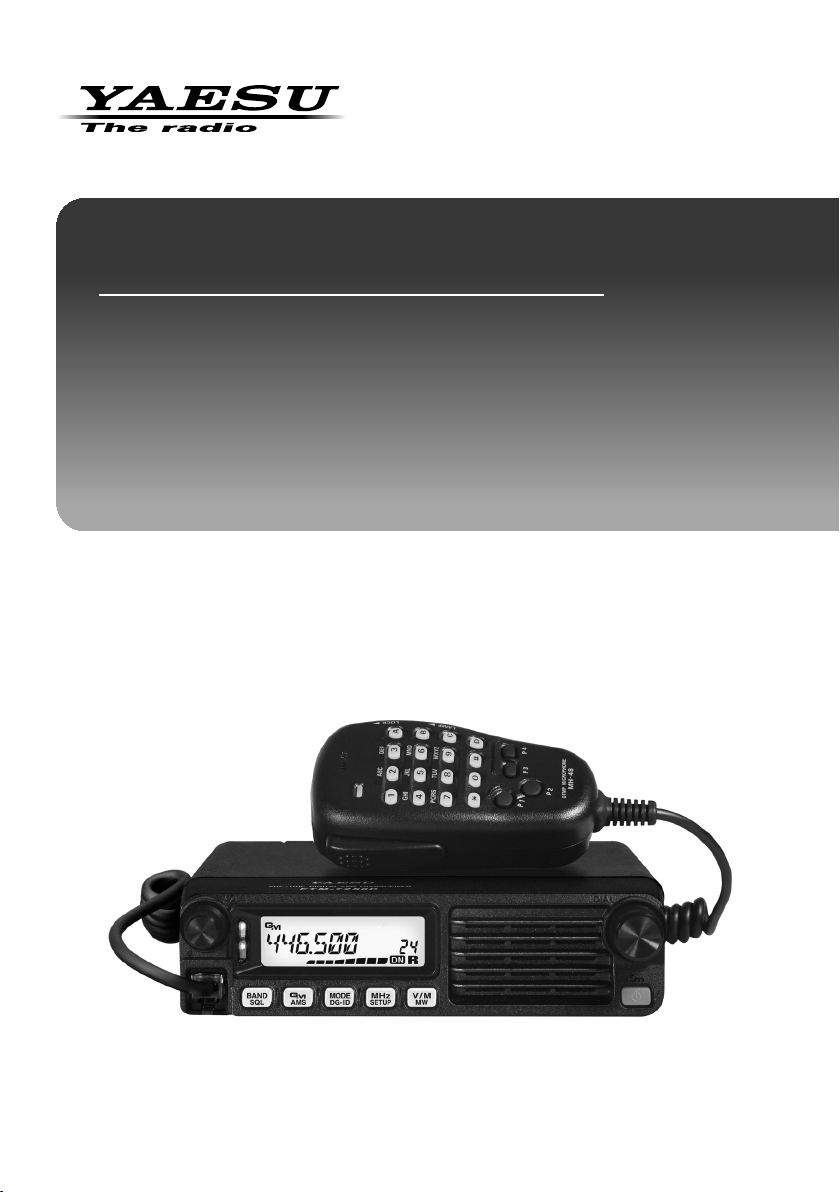
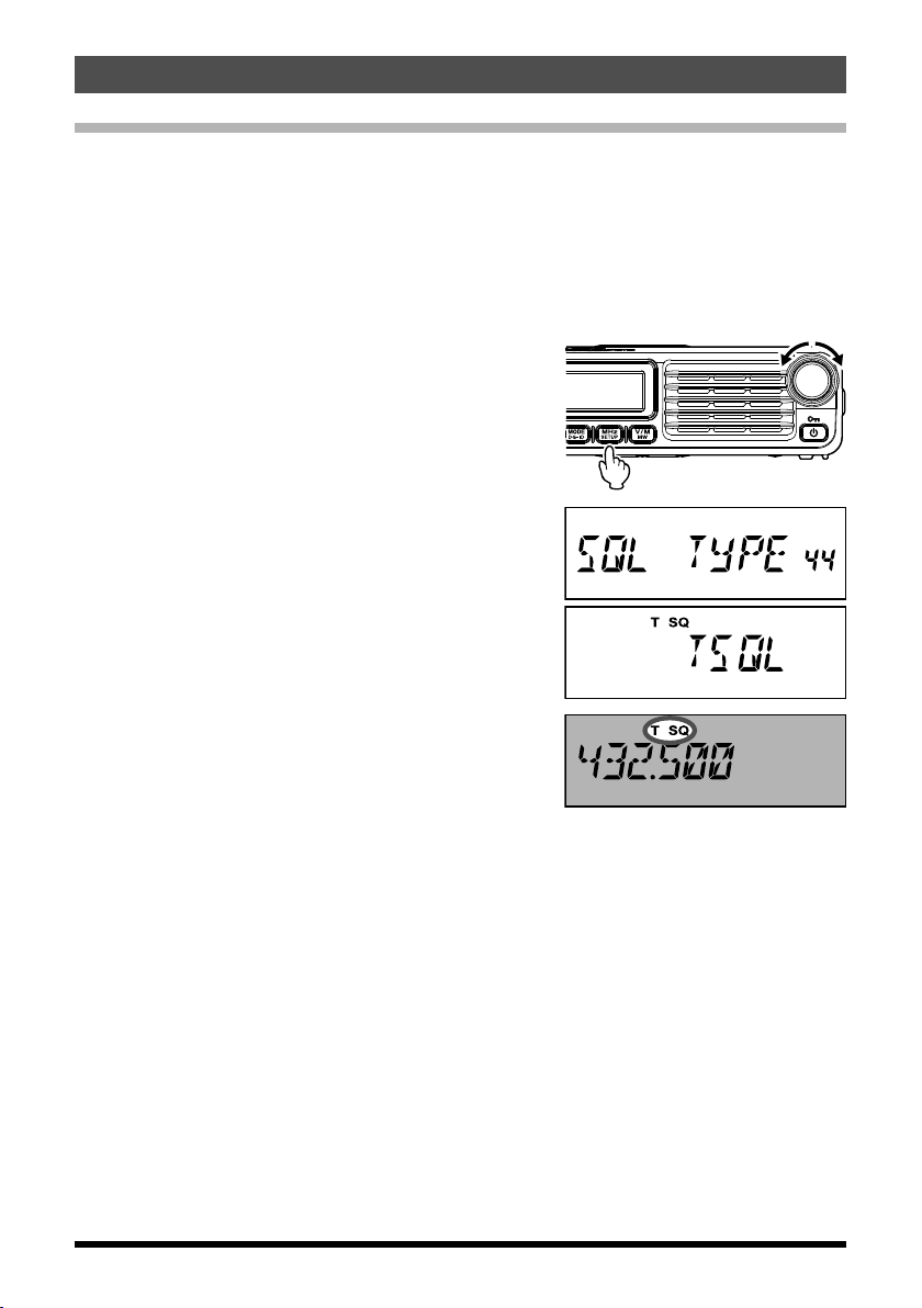
Selecting the Squelch Type in the Analog FM Mode..................................................... 4
CTCSS Operation ......................................................................................................... 5
Tone Search.................................................................................................................. 6
DCS Operation.............................................................................................................. 7
DCS Search .................................................................................................................. 8
Split Tone Operation...................................................................................................... 9
EPCS (Enhanced Paging & Code Squelch) Operation............................................... 10
Storing CTCSS Tone Pairs for EPCS Operation ..................................................... 10
Activating the Enhanced Paging & Code Squelch System...................................... 11
Notification of a Call from a Remote Station by the Bell Function............................... 11
DTMF Operation ......................................................................................................... 13
Transmitting a DTMF code manually....................................................................... 13
Registering a DTMF code........................................................................................ 14
Transmitting the registered DTMF code .................................................................. 15
Setting DTMF Autodialer sending Speed................................................................. 15
Setting DTMF Autodialer TX delay time................................................................... 16
Checking the Repeater Uplink (Input) Frequency....................................................... 16
Memory Operation........................................................................................................ 17
Split Memory ............................................................................................................... 17
Moving Memory Data to the VFO................................................................................ 17
Memory Only Mode..................................................................................................... 17
Naming a Memory Channel ........................................................................................ 18
Scanning ....................................................................................................................... 19
Scan Resume Options ................................................................................................ 19
Memory Skip Scanning ............................................................................................... 20
Preferential Memory Scan........................................................................................... 21
Programmable Memory Scan (PMS) .......................................................................... 22
Band Edge Beeper...................................................................................................... 23
Priority Channel Scanning (Dual Watch)..................................................................... 24
Priority Revert Mode................................................................................................ 24
GM Function.................................................................................................................. 25
About the GM(Group Monitor) feature ........................................................................ 25
GM Alert Beep............................................................................................................. 27
GM Polling Interval...................................................................................................... 27
Clone.............................................................................................................................. 28
Setup (Menu) Mode ...................................................................................................... 29
Menu Selection Details ................................................................................................ 32

2
Basic Operation
Microphone Gain Setting
The microphone gain has been programmed at the factory to a level that should be
satisfactory for the supplied MH-48A6JA Microphone. If an after-market microphone is
used, you may wish to set a different Mic Gain level.
1. Press and hold the [MHz(SETUP)] key to enter the
Set mode.
2. Rotate the DIAL knob to select “MIC GAIN 25”.
3. Press the [MHz(SETUP)] key, then rotate the
DIAL knob to select the desired microphone gain
level (LEVEL 1 - LEVEL 9).
Default: LEVEL 5
4. Press and hold the [MHz(SETUP)] key to save the
new setting and exit to normal operation.
RF Squelch
A special RF Squelch feature is provided on this radio, which allows setting the squelch so
that only signals exceeding a pre-set S-meter level will open the squelch.
Use the following procedure to set up the RF squelch circuit for operation:
1. Press and hold the [MHz(SETUP)] key to enter the
Set mode.
2. Rotate the DIAL knob to select “RF SQL 34”.
3. Press the [MHz(SETUP)] key, then rotate the DIAL
knob to select the desired signal strength level for
the squelch threshold (S1 - S8 or OFF).
Default: OFF
4. Press and hold the [MHz(SETUP)] key to save the
new setting and exit to normal operation.

3
Advanced Operation
Programming the Key Assignments
Default FTM-7250DR key functions have been assigned to the Microphone [P3]/[P4]keys
at the factory. The user may change these key function assignments, if quick access to
another function is desired.
To change the assignments for the programmable keys:
1. Press and hold the [MHz(SETUP)] key, then rotate
the DIAL knob to select the Menu Item to config-
ure the desired microphone button: (“PRG P3 31”
or “PRG P4 32”).
2. Press the [MHz(SETUP)] key, then rotate the
DIAL knob to select the function you wish to as-
sign to the key you selected in the previous step.
The available program functions differ slightly for each of the four keys, the choices
include:
SQL OFF: Open the Squelch to allow un-muted reception.
HOME: Recall the home channel.
WX CH: Activates the WX function (USA Version only).
CD SRCH: Engages the Tone or DCS Search Scanning feature.
SCAN: Engages the Scan operation.
T CALL: Activates 1750 Hz Tone Burst.
TX POWER: Set the transmission power level.
MODE: Change the communication mode (Digital/Analog).
GM: Activates the GM (Group Monitor) function.
WIRES-X: Activates the WIRES-X function.
REV: Reverses the transmit and receive frequencies while working through a
repeater.
DW: Engages Dual Watch feature.
Alternatively, one of the Set Menu items previously assigned may be set. To assign
another desired Set Mode item to a programmable key, see the description in the box
shown below (except Set mode items #31 and #32).
3. Press and hold the [MHz(SETUP)] key to exit to normal operation.
You may assign Set Mode items to the Microphone [P3]/[P4]buttons.
1. Press and hold the [MHz(SETUP)] key to enter the Set mode.
2. Rotate the DIAL knob to select the Set Mode Item that you wish to assign to the
key as a Menu short cut.
3. Press and hold the Microphone’s [P3]or [P4]key to assign the Set Mode Item to
that button.
4. Now you can recall this preferred Set Mode Item by simply pressing the
Microphone button momentarily.

4
Advanced Operation
Selecting the Squelch Type in the Analog FM Mode
1. Press and hold the [MHz(SETUP)] key to enter the Set mode.
2. Rotate the DIAL knob to select “SQL TYPE 44”.
3. Press the [MHz(SETUP)] key, then rotate the DIAL knob to select the squelch type.
Tone squelch (CTCSS), DCS and the New PAGER (EPCS) functions do not operate in the
C4FM digital mode. Press the [MODE(DG-ID)] key to switch the communication mode to AMS
(Auto Mode Select function) or analog (FM) mode.
Squelch type Icon indication Description
OFF -
Deactivates the tone squelch function and DCS function OFF,
then returns to the normal squelch operation in the An-alog
FM mode.
TONE T (appears) Analog FM Transmissions contain the CTCSS tone. Receives
as a normal squelch operation.
TSQL T SQ (appears) Activates the CTCSS tone squelch function on Analog FM
receive.
DCS DCS (appears) Activates the Digital Code Squelch (DCS) function. The DCS
code may be selected from 104 codes (from 023 to 754).
RV TONE T SQ (blinks)
Activates the reverse tone function. Used to monitor commu-
nications based on the squelch control system. When a sig-
nal contains the designated tone, the squelch is not opened,
and when the tone signal disappears, the squelch opens and
communication starts.
PAGER P (appears)
Activates a new two-tone CTCSS pager function. When com-
municating with FTM-7250DR transceivers among friends,
specify personal codes (each code is composed of two tones)
so that you can call only specific stations.
D CODE* DCS (blinks) Transmits the signal containing the DCS CODE. Receives as
a normal squelch operation.
T DCS* T
DCS
(blinks)
(appears)
Sends a tone signal when transmitting, and receives the only
signal matches the DCS code when receiving.
D TONE* T SQ
DCS
(appears)
(blinks)
Sends the DCS CODE when transmitting, and receives only
signals that contain a matching tone signal when receiving.
*: Turning the Set Mode “SQL EXP 43” to ON, “D CODE”, “T DCS” and “D TONE”
setting values are activated.
4. Press and hold the [MHz(SETUP)] key to save the new setting and exit to normal
operation.
zThe squelch type may be set for each frequency band (BAND).
zThe CTCSS and DCS squelch settings are also active during scanning. If scanning is
performed with the CTCSS and DCS squelch function activated, scanning stops only
when a signal containing the specified CTCSS tone or DCS code is received.
zSet Mode [13 DCS.INV] (30) allows to receive the DCS code of the inverted phase.

5
Advanced Operation
CTCSS Operation
This radio is equipped with the CTCSS (Continuous Tone-coded Squelch System) that
allows audio to be heard only when receiving signals containing a tone corresponding to
the tone squelch menu setting. By matching the CTCSS tone with the partner station in
advance, quiet standby monitoring is possible.
Note: CTCSS does not function in digital mode. To transmit a signal using a CTCSS
code, use the [MODE(DG-ID)] key to switch the communication mode to AMS
(Auto Mode Select function) or analog (FM) mode.
1. Press and hold the [MHz(SETUP)] key to enter the
Set mode.
2. Rotate the DIAL knob to select “SQL TYPE 44”.
3. Press the [MHz(SETUP)] key, then rotate the
DIAL knob to select “TSQL”.
4. Press and hold the [MHz(SETUP)] key to save the
new setting and exit to normal operation.
“T SQ” is displayed on the screen. Now the squelch
opens only when receiving tone signals of the set
frequency.
Note: From the Setup Menu, you can change the CTCSS setting.
TONE FRQ 47 àThe tone frequency can be selected from 50 frequencies.
BELL 7 àA bell tone (beep) may be set to sound when signals containing
a corresponding CTCSS tone are received.

6
Advanced Operation
Tone Search
When the CTCSS tone being transmitted by another station is not known, you can tune
the radio to the incoming signal and activate tone scan to search for and identify the tone
being used.
To scan for the tone in use:
1. Set the transceiver up for CTCSS operation (see
page 5 for details.).
“T SQ” will appear on the display.
2. Press the Programmable key on the MH-48A6JA Microphone that is assigned “CD
SRCH” (see page 3) to start scanning for the incoming CTCSS code.
3. When the radio detects the correct tone, scanning will halt on that tone, and audio will
be allowed to pass.
4. Press the assigned Programmable key of the Microphone to lock in that tone and exit
to normal operation.
Note: You may listen to the (muted) signals from the other stations during Tone Scanning
when Set Mode Item “TS MUTE 49” is set to “OFF”. See page 39 for details.
You can also change the Tone Search scanning speed, using Set Mode Item “TS
SPEED 50” See page 39 for details.

7
Advanced Operation
DCS Operation
This radio is equipped with a DCS (Digital Coded Squelch) function that allows audio to
be heard only when signals containing the corresponding DCS code are received. By
matching the DCS code with the partner stations beforehand, a quiet receive standby is
possible..
Note: DCS does not function in digital mode. To transmit a signal with a DCS code, use
the [MODE(DG-ID)] key to switch the communication mode to AMS (Auto Mode
Select function) or analog (FM) mode.
1. Press and hold the [MHz(SETUP)] key to enter the
Set mode.
2. Rotate the DIAL knob to select “SQL TYPE 44”.
3. Press the [MHz(SETUP)] key, then rotate the
DIAL knob to select “DCS”.
4. Press and hold the [MHz(SETUP)] key to save the
new setting and exit to normal operation.
“DCS” is displayed on the screen. The squelch
opens only when receiving a signal containing the
corresponding DCS code..
Note: From the Setup Menu, you can change the DCS setting.
DCS CODE 10 àThe DCS code can be selected from 104 codes.
BELL 7 àA bell tone (beep) may be set to sound when signals containing
a corresponding DCS code are received.

8
Advanced Operation
DCS Search
When the DCS code being transmitted by another station is not known, you can tune the
radio to the incoming signal and activate DCS code scan to search for and identify the
DCS code being used.
To scan for the DCS in use:
1. Set the transceiver up for DCS operation (see the
description in the box shown below.).
“DCS” will appear on the display.
2. Press the Programmable key on the MH-48A6JA Microphone that is assigned “CD
SRCH” (see page 3) to start scanning for the incoming DCS code.
3. When the radio detects the correct code, scanning will halt on that code, and audio will
be allowed to pass.
4. Press the assigned Programmable key of the Microphone to lock in that tone and exit
to normal operation.
Note: You may listen to the (muted) signals from the other stations during DCS Scanning
when Set Mode Item “TS MUTE 49” is set to “OFF”. See page 39 for details.
You can also change the DCS Search scanning speed, using Set Mode Item “TS
SPEED 50” See page 39 for details.

9
Advanced Operation
Split Tone Operation
The FTM-7250DR can be configured to operate in a “Split Tone” system via the Setup
menu, to facilitate operation on repeaters using a mix of both CTCSS and DCS control.
1. Press and hold the [MHz(SETUP)] key to enter the
Set mode.
2. Rotate the DIAL knob to select “SQL EXP 43”.
3. Press the [MHz(SETUP)] key, then rotate the
DIAL knob to select “ON”.
Default: OFF
4. Press the [MHz(SETUP)] key momentarily, then
rotate the DIAL knob to select “SQL TYPE 44”.
5. Press the [MHz(SETUP)] key, and then rotate the
DIAL knob to select the following parameters.
D CODE: DCS Encode only (the “DCS” icon will
blink during operation)
T DCS: Encodes a CTCSS Tone and Decodes
a DCS code (the “T” icon will blink and
the “DCS” icon will appear during oper-
ation)
D TONE: Encodes a DCS code and Decodes a
CTCSS Tone (the “T SQ” icon will ap-
pear and “DCS” icons will blink during
operation)
6. Press and hold the [MHz(SETUP)] key to save the new setting and exit to normal
operation.

10
Advanced Operation
EPCS (Enhanced Paging & Code Squelch) Operation
The FTM-7250DR includes an Enhanced CTCSS tone encoder/decoder and a dedicated
microprocessor providing paging and selective calling features. This allows placing a call
to a specific station (Paging), and choosing to receive calls directed only to you (Code
Squelch).
The paging and code squelch systems use two pairs of (alternately switched) CTCSS
tones, which are stored in the pager memories. Basically, your receiver remains silent until
it receives the CTCSS tone pair that matches those stored in the Receiving Pager Memory.
The squelch then opens so the caller is heard, and the paging ringer immediately sounds,
if activated. When you close the PTT switch to transmit, the CTCSS tone pair that is
stored in the Transmitting Pager Memory will be transmitted automatically.
On the paged radio, the squelch will close automatically after the incoming page ends.
Storing CTCSS Tone Pairs for EPCS Operation
1. Press and hold the [MHz(SETUP)] key to enter the
Set mode.
2. Rotate the DIAL knob to select “PAG CD-R 29” for
the Receiving CTCSS Tone Pair or “PAG CD-T 30”
for the Transmitting CTCSS Tone Pair.
3. Press the [MHz(SETUP)] key momentarily to en-
able adjustment of this Set Mode Item.
4. Rotate the DIAL knob to set the CTCSS Tone
number, which corresponds to the first tone of the
CTCSS Tone Pair.
5. Press the [BAND(SQL)] or [V/M(MW)] key, then
rotate the DIAL knob to set the CTCSS Tone num-
ber, which corresponds to the second tone of the
CTCSS Tone Pair.
6. Press and hold the [MHz(SETUP)] key to lock in that tone and exit to normal operation.
Note: The FTM-7250DR does not recognize the order of the 1st tone and the 2nd tone.
In other words, for example, the FTM-7250DR considers both CTCSS pairs “05,
47” and “47, 05” to be identical.

11
Advanced Operation
Activating the Enhanced Paging & Code Squelch System
1. Press and hold the [MHz(SETUP)] key to enter the
Set mode.
2. Rotate the DIAL knob to select “SQL TYPE 44”.
3. Press the [MHz(SETUP)] key, and then rotate the
DIAL knob to select “PAGER”.
Default: OFF
4. Press and hold the [MHz(SETUP)] key to save the new setting and exit to normal
operation.
5. To disable the Enhanced Paging & Code Squelch, just repeat the above procedure,
rotating the DIAL knob to select “OFF” in step 3 above.
When the Enhanced Paging & Code Squelch feature
is activated, the “P” notation will appear on the right
of the frequency display.
Notification of a Call from a Remote Station by the Bell Function
The Bell may be set to sound an Alert when a call from another station containing a cor-
responding tone, DCS or pager code is received. “ ” icon on the LCD blinks to provide a
later notice of the call from the other station.
1. Press and hold the [MHz(SETUP)] key to enter the
Set mode.
2. Rotate the DIAL knob to select “BELL 7”.
2. Press the [MHz(SETUP)] key.

12
Advanced Operation
3. Rotate the DIAL knob to select the desired num-
ber of times (1-20 times or continuous) the Bell
rings.
Default: OFF
àOFF à1 TIME à2 TIMES àà20 TIMES àCONTINUE (continuous) à
4. Press and hold the [MHz(SETUP)] key to save the new setting and exit to normal op-
eration.

13
Advanced Operation
DTMF Operation
DTMF tones (Dual Tone Multi Frequencies) are the tones you hear when dialing from a
telephone keypad. The FTM-7250DR transceiver can transmit the DTMF codes by using
the keys on the microphone or recalling registered number strings from memories.
The maximum of 16-digit DTMF codes can be registered in up to 10 memory channels.
It is convenient to register telephone patch numbers, and network linking sequences to
the DTMF memory channels.
Note: The two combined frequencies of the DTMF tone transmitted for each key are
indicated in the following table:
1209 Hz 1336 Hz 1477 Hz 1633 Hz
697 Hz 1 2 3 A
770 Hz 4 5 6 B
852 Hz 7 8 9 C
941 Hz ]0 # D
Transmitting a DTMF code manually
You can generate DTMF tones during transmission manually.
1. Press and hold the [MHz(SETUP)] key to enter the
Set mode.
2. Rotate the DIAL knob to select “DT AUTO 16”.
3. Press the [MHz(SETUP)] key momentarily, and
then rotate the DIAL knob to select “MANUAL”.
4. Press and hold the [MHz(SETUP)] key to save the new setting and exit to normal op-
eration.
5. While pressing and holding PTT, press the desired DTMF characters ([0]to [9], []], [#],
or [A]to [D]), sequentially on the microphone keypad.
6 Release PTT.
While transmitting the DTMF code, transmission status is sustained even when PTT is
released.

14
Advanced Operation
Registering a DTMF code
1. Press and hold the [MHz(SETUP)] key to enter the
Set mode.
2. Rotate the DIAL knob to select “DT SET 18”.
3. Press the [MHz(SETUP)] key momentarily, then
rotate the DIAL knob to select the desired memory
channel (C0 to C9) to register the DTMF code.
4. Press the [V/M(MW)] key momentarily, then rotate
the DIAL knob to select the first digit of the DTMF
code.
Note: You can also use the keypad on the micro-
phone to input the DTMF code.
5. When you have selected the correct digit, press
the [V/M(MW)] key momentarily. Now, rotate the
DIAL knob to select the second of 16 available
numbers in the current DTMF Autodialer memory
register.
6. Repeat this procedure for each digit in the DTMF code.
Note: mTo make a correction, press the [BAND(SQL)] key to back-space the cursor,
then re-enter the correct number.
mPress and hold the [GM(AMS)] key to delete all data after the cursor that may
have been previously stored.
7. When entry of all digits is complete, press and hold the [MHz(SETUP)] key to set the
DTMF code and exit to normal operation.

15
Advanced Operation
Transmitting the registered DTMF code
1. Press and hold the [MHz(SETUP)] key to enter the
Set mode.
2. Rotate the DIAL knob to select “DT AUTO 16”.
3. Press the [MHz(SETUP)] key momentarily, and
then rotate the DIAL knob to select “AUTO”.
4. Press and hold the [MHz(SETUP)] key to save the new setting and exit to normal op-
eration.
Note: While the DTMF Autodialer is activated, the
“” icon will appear on the LCD.
5. In the Autodialer mode, which you just engaged, first press the PTT switch, then press
the microphone numeric key ([0]through [9]) corresponding to the DTMF memory
string you wish to send. Once the string begins, you may release the PTT switch, as
the transmitter will be held “on the air” until the DTMF string is completed.
To disable the Autodialer function mode, select “MANUAL” in step 3 above.
Setting DTMF Autodialer sending Speed
The speed at which the DTMF digits are sent can be changed.
1. Press and hold the [MHz(SETUP)] key to enter the
Set mode.
2. Rotate the DIAL knob to select “DT SPEED 19”.
3. Press the [MHz(SETUP)] key momentarily, and
then rotate the DIAL knob to select the desired
speed (“50 MS”: High speed or “100 MS”: Low
speed).
4. Press and hold the [MHz(SETUP)] key to save the
new setting and exit to normal operation.

16
Advanced Operation
Setting DTMF Autodialer TX delay time
A longer delay may be set between the time the transmitter is keyed and the first DTMF
digit is sent:
1. Press and hold the [MHz(SETUP)] key to enter the
Set mode.
2. Rotate the DIAL knob to select “DT DELAY 17”.
3. Press the [MHz(SETUP)] key momentarily, and
then rotate the DIAL knob to select the desired
delay time (50 MS / 250 MS / 450 MS / 750 MS /
1000 MS).
Default: 450 MS
4. Press and hold the [MHz(SETUP)] key to save the
new setting and exit to normal operation.
Checking the Repeater Uplink (Input) Frequency
It is often helpful to be able to check the uplink (input) frequency of a repeater, to see if
the calling station is within direct (“Simplex”) range.
Note: This function can only be used through the programmable keys [P1] to [P4] on the
microphone.
Refer to the “Programming the Key Assignments“ on page page 3.
To do this (Example: When “REV” is assigned to [P4]):
1. Press the Microphone [P4]key.
You’ll notice that the display has shifted to the re-
peater uplink frequency.
While listening on the repeater input frequency us-
ing the [P4]key, the repeater offset icon will blink.
2. Press the [P4]key again to cause operation to revert to normal monitoring of the re-
peater downlink (output) frequency.

17
Memory Operation
Split Memory
A separate transmit frequency may be registered to a memory channel to which a receive
frequency has already been registered.
1. In the VFO mode, select the transmit frequency to be registered.
2. Press and hold the [V/M(MW)] key.
A memory number will appear in the bottom right corner of the display.
3. Rotate the DIAL knob (if necessary) to select the memory channel to which the trans-
mit frequency is to be registered.
4. Press and hold the PTT, and press the [V/M(MW)] key momentarily while holding in
the PTT. This will not cause transmission, but rather it will instruct the transceiver to
program the separate transmit frequency into memory.
Whenever a memory which contains independently
stored transmit and receive frequencies is recalled,
the “
-
+” indication will appear in the display.
Moving Memory Data to the VFO
The data stored on a memory channel can easily be moved to the VFO.
1. Select the memory channel containing the frequency data to be moved to the VFO.
2. Press and hold the [V/M(MW)] key, and then press
the [MHz(SETUP)] key. The “VFO WRT?” will ap-
pear on the display.
3. Press the [V/M(MW)] key, the data will now have been copied to the VFO, although the
original memory contents will remain intact on the previously-stored channel.
Note: If a split Frequency Memory channel was transferred, the TX frequency will be
ignored (The transceiver will be set up for Simplex operation on the Receive
frequency.)
Memory Only Mode
When memory channel programming has been completed, you may place the radio in
a “Memory Only” mode, whereby VFO operation is impossible. This may be particularly
useful during public-service events where a number of operators may be using the radio
for first time, and ultimate simplicity of channel selection is desired.
To place the radio into the Memory Only mode, turn the transceiver OFF. Now press and
hold the [V/M(MW)] key while turning the transceiver ON. The VFO and Home Channel
will now be disabled.
To return to normal operation, repeat the above power-on procedure.

18
Memory Operation
Naming a Memory Channel
You may wish to append an alphanumeric “Tag” (label) to each memory, to aid in
recollection of the channel’s use (such as club name, etc.).
1. Recall the memory channel on which you wish to append a label.
2. Press and hold the [MHz(SETUP)] key to enter the
Set mode.
3. Rotate the DIAL knob to select “MEM NAME 26”.
4. Press the [MHz(SETUP)] key momentarily to en-
able programming of the nametag.
5. Use the numeric keypad or DIAL knob to input the
characters.
Press the [V/M(MW)] key to move to the next
character.
• Inputting characters
Example quickly Pressing the [2]key, each
time switches the following characters:
a → b → c → A → B → C → a →
Example Rotating the DIAL switches the fol-
lowing characters.
••• A - Z (symbol) a - z (symbol)
0 - 9 (symbol) •••
• Moving the cursor, deleting the input character
[V/M(MW)] key: Moves the cursor to the right
[BAND (SQL)] key: Moves the cursor to the right
Pressing and holding the [GM (AMS)] key: Erases all characters after the cursor
6. Repeat step 5 to program the remaining letters, numbers, or symbols of the desired
label. A total of 8 characters may be used in the creation of a label.
7. When you have programmed a label that is under 8 characters, press the [MHz(SET-
UP)] key to confirm the label.
8. When you have completed the creation of the label, then press and hold the [V/M(MW)]
key to save the label and exit.
While operating in the Memory Recall mode, press
the [MHz(SETUP)] key to toggle the display between
indication of the frequency, and indication of the
Alpha/Numeric label.

19
Scanning
Scan Resume Options
Select one of the three receiving operations to be performed after the scanning stops.
(1) Restart scanning after receiving the frequency for the set amount of time. Select from
2.0 to 10.0 seconds (0.5 step).
(2) Continue receiving the frequency until the signal disappears, and then restart scan-
ning 2 seconds after the signal disappears (BUSY).
(3) Stop scanning and receive that frequency (HOLD).
1. Press and hold the [MHz(SETUP)] key to enter the
Set mode.
2. Rotate the DIAL knob to select “SCAN RSM 39”.
3. Press the [MHz(SETUP)] key, then rotate the DIAL
knob to select the desired scan-resume mode.
Default: 5.0 SEC
4. Press and hold the [MHz(SETUP)] key to save the
new setting and exit to normal operation.
Other manuals for FTM-7250DR
2
Table of contents
Other Yaesu Transceiver manuals

Yaesu
Yaesu FT-8800 Service manual

Yaesu
Yaesu FT-900 User manual

Yaesu
Yaesu FT-897 Manual

Yaesu
Yaesu VX-2500V User manual

Yaesu
Yaesu FT-2700RH User manual

Yaesu
Yaesu FTDX101D User manual

Yaesu
Yaesu FTM-400XDE Reference guide

Yaesu
Yaesu FT-901DM User manual

Yaesu
Yaesu FT5De User manual

Yaesu
Yaesu VX-6R User manual

Yaesu
Yaesu FT DX 1200 User manual

Yaesu
Yaesu FT-901DM User manual

Yaesu
Yaesu FT-857 series User manual

Yaesu
Yaesu FTM-350AR User manual

Yaesu
Yaesu FT-227R Memorizer User manual

Yaesu
Yaesu FT-790R User manual

Yaesu
Yaesu FT-8800R User manual

Yaesu
Yaesu VX-5R User manual

Yaesu
Yaesu FTM-200DR User manual

Yaesu
Yaesu FT-2900R Manual