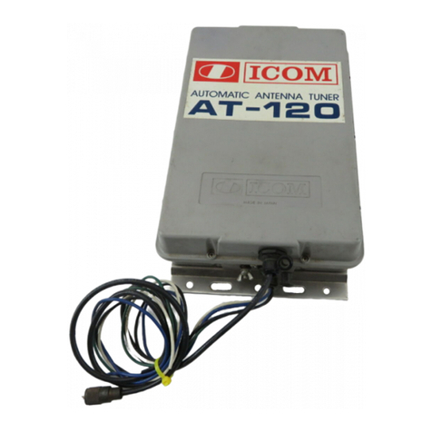
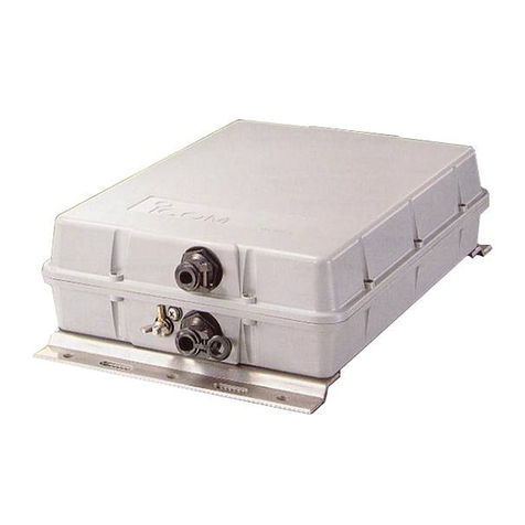
Icom AH-705 User manual

INSTRUCTIONS
AUTOMATIC ANTENNA TUNER Thank you for choosing this Icom product.
READ ALL INSTRUCTIONS carefully and completely
before using this product.
1-1-32 Kamiminami, Hirano-ku, Osaka 547-0003, Japan
Jan. 2021
A7630W-1EX Printed in Japan
© 2021 Icom Inc. –1 –
–4 –
AH-705
■Important
SAVE THESE INSTRUCTIONS— These instructions
contain important operating instructions for the AH-705.
■Features
• IP54* dust protection and splash resistance construction
* Only when the jack covers are attached.
• You can use the AH-705 with AA (LR6) size alkaline
batteries, or an external DC power source.
• The AH-705 provides reliable matching from 1.8 MHz to
54 MHz, using a long wire element.
■Explicit denitions
WORD DEFINITION
RDANGER! Personal death, serious injury or an
explosion may occur.
RWARNING! Personal injury, fire hazard or electric shock
may occur.
CAUTION Equipment damage may occur.
NOTE If disregarded, inconvenience only. No risk
of personal injury, fire or electric shock.
Icom is not responsible for the destruction, damage to, or
performance of any Icom or non-Icom equipment, if the
malfunction is because of:
• Force majeure, including, but not limited to, fires, earthquakes,
storms, floods, lightning, other natural disasters, disturbances,
riots, war, or radioactive contamination.
• The use of Icom antenna tuners with any equipment that is not
manufactured or approved by Icom.
Icom, Icom Inc. and the Icom logo are registered trademarks of
Icom Incorporated (Japan) in Japan, the United States, the United
Kingdom, Germany, France, Spain, Russia, Australia, New Zealand,
and/or other countries.
■Precautions
RDANGER HIGH RF VOLTAGE! NEVER touch an antenna
or antenna connector while transmitting or tuning. This could
cause an electrical shock or burn.
RDANGER HIGH RF VOLTAGE! NEVER install the antenna
tuner at any place that person easily touch the antenna or
antenna connector while transmitting or tuning. This could
cause an electrical shock or burn.
RWARNING! NEVER use the antenna tuner during a lightning
storm. It may result in an electric shock, cause a fire or damage
the tuner. Always disconnect the power source and antenna
before a storm.
RWARNING! NEVER touch the antenna tuner with wet hands.
This may result in an electrical shock or damage the tuner.
RWARNING! NEVER apply AC power to the [DC IN] jack on
the antenna tuner. This could cause a fire or damage the tuner.
RWARNING! NEVER apply more than 16 V DC to the [DC IN]
jack on the antenna tuner. This could cause a fire or damage
the tuner.
RWARNING! NEVER reverse the DC power cable polarity.
This could cause a fire or damage the antenna tuner.
RWARNING! NEVER let metal, wire or other objects contact
the inside of the antenna tuner, or make incorrect contact with
connectors. This could cause an electric shock or damage the tuner.
RWARNING! NEVER operate the antenna tuner without a solid
ground. Always connect the ground wire to the ground terminal.
CAUTION: DO NOT transmit or tune without an antenna
connected. This could cause damage to the antenna tuner.
CAUTION: DO NOT put the antenna tuner in any unstable
place, such as on a slanted surface or a place that vibrates.
This may cause an injury and/or damage the tuner.
CAUTION: DO NOT use harsh solvents such as Benzine or
alcohol to clean the antenna tuner, as they can damage the
tuner’s surfaces. If the tuner becomes dusty or dirty, wipe it
clean with a dry, soft cloth.
KEEP the antenna tuner away from heavy rain, and never
immerse it in water. The tuner meets IP54* requirements for
dust-protection and splash resistance. However, once the
tuner has been dropped, dust-protection and splash resistance
cannot be guaranteed because of possible damage to the
tuner’s case or the waterproof seal.
* Only when the jack covers are attached.
DO NOT place or leave the antenna tuner in excessively dusty
environments.
DBattery cautions
RDANGER! NEVER incinerate used battery cells since the
internal battery gas may cause them to rupture.
CAUTION: Remove the alkaline batteries when the antenna
tuner will not be used for a long period of time. Otherwise, the
installed alkaline batteries may leak and damage the tuner.
When installing batteries, confirm that they are all the same brand,
type and capacity. DO NOT mix new and old batteries together.
DO NOT use batteries whose insulated covering is damaged.
■FCC information
This equipment has been tested and found to comply with
the limits for a Class B digital device, pursuant to part 15
of the FCC Rules. These limits are designed to provide
reasonable protection against harmful interference in a
residential installation. This equipment generates, uses,
and can radiate radio frequency energy and, if not installed
and used in accordance with the instructions, may cause
harmful interference to radio communications. However,
there is no guarantee that interference will not occur in a
particular installation. If this equipment does cause harmful
interference to radio or television reception, which can be
determined by turning the equipment off and on, the user is
encouraged to try to correct the interference by one or more
of the following measures:
• Reorient or relocate the receiving antenna.
• Increase the separation between the equipment and receiver.
• Connect the equipment into an outlet on a circuit different from
that to which the receiver is connected.
• Consult the dealer or an experienced radio/TV technician for help.
CAUTION: Changes or modifications to this device, not
expressly approved by Icom Inc., could void your authority
to operate this device under FCC regulations.
This device complies with part 15 of the FCC Rules.
Operation is subject to the following two conditions: (1) This
device may not cause harmful interference, and (2) this
device must accept any interference received, Including
interference that may cause undesired operation.
■Disposal
The crossed-out wheeled-bin symbol on your
product, literature, or packaging reminds you
that in the European Union, all electrical and
electronic products, batteries, and accumulators
(rechargeable batteries) must be taken to
designated collection locations at the end of their working
life. Do not dispose of these products as unsorted municipal
waste. Dispose of them according to the laws in your area.
■About CE and DOC
Hereby, Icom Inc. declares that the versions
of AH-705 which have the “CE” symbol on the
product, comply with the essential requirements
of the Radio Equipment Directive, 2014/53/EU,
and the restriction of the use of certain hazardous substances
in electrical and electronic equipment Directive, 2011/65/EU.
The full text of the EU declaration of conformity is available at
the following internet address:
https://www.icomjapan.com/support/
■Specications
• Frequency range: 1.8 ~ 54 MHz
1.8 MHz band: with an antenna longer than 30 m, 98.4 ft
3.5 MHz band and above: with an antenna longer than 7 m, 23 ft
• Maximum input power: 10 W
•
• Tuning power required: 5 ~ 10 W
• Automatic tuning time: Approximately 2 to 3 seconds
(general conditions)
Maximum 15 seconds
• Power supply: 3.0 V for two AA (LR6) size
alkaline batteries
13.8 V DC (±15%)
for external DC power
• Current drain: Standby Less than 1 mA
Tuning Less than 300 mA
•
• VSWR: 1 : 2.0 or less
(except antennas one half wave or a multiple of a one half
wave in length)
• Number of tuned memories:45 memories
• Dimensions:
190 (W) × 105 (H) × 40 (D) mm,
7.5 (W) × 4.1 (H) × 1.6 (D) inches
(Projections not included)
• Weight (approximate): 450 g, 15.8 oz
(Without batteries)
LAll stated specifications are typical and subject to change without
notice or obligation.
■Operation
1. Turn ON the transceiver.
2. Select an operating frequency.
3. Push .
4. Touch 2at the bottom of the screen.
5. Touch [TUNER].
• The transceiver automatically starts transmitting and tuning.
The tuner reduces the SWR to less than 2:1 after 2 ~ 3
seconds of tuning.
LWhile tuning, a side tone is heard, and “TUNE” blinks.
LTouching [TUNER] turns the AH-705 ON or OFF (bypassed).
6. After tuning, “TUNE” is displayed.
LIf the tuner cannot reduce the SWR to less than 2:1 after 15
seconds of tuning, the indicator goes out.
LWhen a long wire antenna cannot be tuned, the indicator
goes out. In that case, the tuner is bypassed, and the wire is
directly connected.
LTo manually tune the antenna, touch [TUNER] for 1 second.
RDANGER HIGH VOLTAGE! NEVER touch the antenna
element while tuning or transmitting. This could cause an
electrical shock or burn.
NOTE:
• When the wire antenna cannot be tuned, check the wire
length and connection. The AH-705 cannot tune a wire
• The AH-705 uses latching relays with low power
consumption. The latching relays themselves
memorize the operating state, but they may not hold
the settings after a strong impact to the tuner. If the
SWR significantly changes during operation, retune the
antenna.
TIP: If your IC-705 version is 1.20 or later:
• The transmit power is set to 5 W while tuning.*
• You can turn the Tune Memory function ON or OFF.*
The Tune Memory function saves the latching relay
combination for quicker antenna tuning.
• You can update the antenna tuner’s firmware using the
transceiver. Updating the firmware adds new functions
and/or improves performance parameters.
You can download the latest firmware from the Icom
website.
https://www.icomjapan.com/support/
* Only when “Tuner Select” is set to “AH-705” (default).
LSee the transceiver’s instruction manual for details.

–3 –– 2 –
NOTE:
• Disconnect the control cable from the antenna
tuner when the tuner will not be used for some time.
Otherwise, the installed alkaline batteries will become
exhausted.
• When the batteries are almost exhausted, the antenna
tuner is automatically turned OFF. Replace all batteries
with new alkaline batteries.
■About power supply
DUsing the alkaline batteries
The AH-705 uses two AA (LR6) size alkaline batteries.
1. Use a coin or standard screwdriver (1), and turn the
screw clockwise one quarter turn (2).
2. Open the battery cover, and Install two AA (LR6) size
alkaline batteries.
LInstall only alkaline batteries.
LBE SURE to observe the correct polarity.
3. Securely attach the battery cover.
Battery cover Screw position
when removing
the battery cover.
Screw position
after attaching the
battery cover.
DUsing an external DC power source
RWARNING! NEVER reverse the DC power cable polarity.
1. Build a power cable for the external DC power source.
2. Connect the antenna tuner to an external DC power
source.
LConfirm that the external DC power source is OFF before
connecting the DC power cable.
Supplied DC plug Cable (User supplied)
■Connection
■Installation
Install the antenna tuner on a pole, as shown below.
1. Attach the supplied bracket to the back of the antenna
tuner, by using a coin or standard screwdriver.
You can hang the antenna
tuner, by threading a piece
of cord through the bracket.
Installation example:
2. Thread the strap through
the bracket slots.
Correct position Incorrect position
Groove
Rubber seal
Battery cover
+
_
_
Center positive
To [DC IN] jack
GND
AH-705 Control cable
(Supplied cable: 2 m, 6.5 ft
Optional cable: 5 m, 16.4 ft)
To [TUNER] jack
To [ANT] connector
To [CTRL] jack
GND
IC-705
To antenna
connector
Supplied Terminal
Connector adapter
You can also connect
a banana plug.
Long wire antenna
Strap (User supplied)
Supplied screw
Supplied washer
Supplied bracket
Battery cover
NOTE:
• Keep the antenna tuner as far away from the transceiver
as possible.
• DO NOT expose the tuner to rain, snow, or any liquids,
when the jack covers are detached. Dust-protection and
splash resistance cannot be guaranteed.
• Using the tuner with a Loop antenna that is not suitable
for the operating frequency cannot be guaranteed.
NOTE: The antenna tuner must have an adequate ground connection. Otherwise, the overall efficiency of the transceiver and
antenna tuner installation will be reduced. Interference, RF feedback, and electrical shocks from other equipment could also
occur.
For best results, connect a heavy gauge wire or strap to a long ground rod. Make the distance between the [GND] terminal
and ground as short as possible.
• A long wire connected to the [GND] terminal can be used as a counterpoise.
GND
External power
source
3. Mount the antenna tuner on a pole.
Be sure that the rubber seal is correctly seated in the groove,
and there is no dust or other material on it.
22 mm (0.9 inch)
2 mm
(0.1 inch) 5.3 mm
(0.2 inch)
Slot dimensions
HF/6 m antenna
Antenna element
Coaxial cable
■Options
• OPC-2474
Cable length: 5 m (16.4 ft)
• OPC-2475
Cable length: 5 m (16.4 ft)
■Supplied accessories
Coaxial cable
(2 m, 6.5 ft)
Control cable
(2 m, 6.5 ft)
DC plug
LAlkaline batteries, a strap or cord for mounting, and a
power cable are not supplied.
Terminal Connector adapter
(PL-259 to Binding Post adapter)
Washer
Bracket
Screw
Coaxial cable
(Supplied cable: 2 m, 6.5 ft
Optional cable: 5 m, 16.4 ft)
GND

INSTRUCTIONS
AUTOMATIC ANTENNA TUNER Thank you for choosing this Icom product.
READ ALL INSTRUCTIONS carefully and completely
before using this product.
1-1-32 Kamiminami, Hirano-ku, Osaka 547-0003, Japan
Jan. 2021
A7630W-1EX Printed in Japan
© 2021 Icom Inc. –1 –
–4 –
AH-705
■Important
SAVE THESE INSTRUCTIONS— These instructions
contain important operating instructions for the AH-705.
■Features
• IP54* dust protection and splash resistance construction
* Only when the jack covers are attached.
• You can use the AH-705 with AA (LR6) size alkaline
batteries, or an external DC power source.
• The AH-705 provides reliable matching from 1.8 MHz to
54 MHz, using a long wire element.
■Explicit denitions
WORD DEFINITION
RDANGER! Personal death, serious injury or an
explosion may occur.
RWARNING! Personal injury, fire hazard or electric shock
may occur.
CAUTION Equipment damage may occur.
NOTE If disregarded, inconvenience only. No risk
of personal injury, fire or electric shock.
Icom is not responsible for the destruction, damage to, or
performance of any Icom or non-Icom equipment, if the
malfunction is because of:
• Force majeure, including, but not limited to, fires, earthquakes,
storms, floods, lightning, other natural disasters, disturbances,
riots, war, or radioactive contamination.
• The use of Icom antenna tuners with any equipment that is not
manufactured or approved by Icom.
Icom, Icom Inc. and the Icom logo are registered trademarks of
Icom Incorporated (Japan) in Japan, the United States, the United
Kingdom, Germany, France, Spain, Russia, Australia, New Zealand,
and/or other countries.
■Precautions
RDANGER HIGH RF VOLTAGE! NEVER touch an antenna
or antenna connector while transmitting or tuning. This could
cause an electrical shock or burn.
RDANGER HIGH RF VOLTAGE! NEVER install the antenna
tuner at any place that person easily touch the antenna or
antenna connector while transmitting or tuning. This could
cause an electrical shock or burn.
RWARNING! NEVER use the antenna tuner during a lightning
storm. It may result in an electric shock, cause a fire or damage
the tuner. Always disconnect the power source and antenna
before a storm.
RWARNING! NEVER touch the antenna tuner with wet hands.
This may result in an electrical shock or damage the tuner.
RWARNING! NEVER apply AC power to the [DC IN] jack on
the antenna tuner. This could cause a fire or damage the tuner.
RWARNING! NEVER apply more than 16 V DC to the [DC IN]
jack on the antenna tuner. This could cause a fire or damage
the tuner.
RWARNING! NEVER reverse the DC power cable polarity.
This could cause a fire or damage the antenna tuner.
RWARNING! NEVER let metal, wire or other objects contact
the inside of the antenna tuner, or make incorrect contact with
connectors. This could cause an electric shock or damage the tuner.
RWARNING! NEVER operate the antenna tuner without a solid
ground. Always connect the ground wire to the ground terminal.
CAUTION: DO NOT transmit or tune without an antenna
connected. This could cause damage to the antenna tuner.
CAUTION: DO NOT put the antenna tuner in any unstable
place, such as on a slanted surface or a place that vibrates.
This may cause an injury and/or damage the tuner.
CAUTION: DO NOT use harsh solvents such as Benzine or
alcohol to clean the antenna tuner, as they can damage the
tuner’s surfaces. If the tuner becomes dusty or dirty, wipe it
clean with a dry, soft cloth.
KEEP the antenna tuner away from heavy rain, and never
immerse it in water. The tuner meets IP54* requirements for
dust-protection and splash resistance. However, once the
tuner has been dropped, dust-protection and splash resistance
cannot be guaranteed because of possible damage to the
tuner’s case or the waterproof seal.
* Only when the jack covers are attached.
DO NOT place or leave the antenna tuner in excessively dusty
environments.
DBattery cautions
RDANGER! NEVER incinerate used battery cells since the
internal battery gas may cause them to rupture.
CAUTION: Remove the alkaline batteries when the antenna
tuner will not be used for a long period of time. Otherwise, the
installed alkaline batteries may leak and damage the tuner.
When installing batteries, confirm that they are all the same brand,
type and capacity. DO NOT mix new and old batteries together.
DO NOT use batteries whose insulated covering is damaged.
■FCC information
This equipment has been tested and found to comply with
the limits for a Class B digital device, pursuant to part 15
of the FCC Rules. These limits are designed to provide
reasonable protection against harmful interference in a
residential installation. This equipment generates, uses,
and can radiate radio frequency energy and, if not installed
and used in accordance with the instructions, may cause
harmful interference to radio communications. However,
there is no guarantee that interference will not occur in a
particular installation. If this equipment does cause harmful
interference to radio or television reception, which can be
determined by turning the equipment off and on, the user is
encouraged to try to correct the interference by one or more
of the following measures:
• Reorient or relocate the receiving antenna.
• Increase the separation between the equipment and receiver.
• Connect the equipment into an outlet on a circuit different from
that to which the receiver is connected.
• Consult the dealer or an experienced radio/TV technician for help.
CAUTION: Changes or modifications to this device, not
expressly approved by Icom Inc., could void your authority
to operate this device under FCC regulations.
This device complies with part 15 of the FCC Rules.
Operation is subject to the following two conditions: (1) This
device may not cause harmful interference, and (2) this
device must accept any interference received, Including
interference that may cause undesired operation.
■Disposal
The crossed-out wheeled-bin symbol on your
product, literature, or packaging reminds you
that in the European Union, all electrical and
electronic products, batteries, and accumulators
(rechargeable batteries) must be taken to
designated collection locations at the end of their working
life. Do not dispose of these products as unsorted municipal
waste. Dispose of them according to the laws in your area.
■About CE and DOC
Hereby, Icom Inc. declares that the versions
of AH-705 which have the “CE” symbol on the
product, comply with the essential requirements
of the Radio Equipment Directive, 2014/53/EU,
and the restriction of the use of certain hazardous substances
in electrical and electronic equipment Directive, 2011/65/EU.
The full text of the EU declaration of conformity is available at
the following internet address:
https://www.icomjapan.com/support/
■Specications
• Frequency range: 1.8 ~ 54 MHz
1.8 MHz band: with an antenna longer than 30 m, 98.4 ft
3.5 MHz band and above: with an antenna longer than 7 m, 23 ft
• Maximum input power: 10 W
•
• Tuning power required: 5 ~ 10 W
• Automatic tuning time: Approximately 2 to 3 seconds
(general conditions)
Maximum 15 seconds
• Power supply: 3.0 V for two AA (LR6) size
alkaline batteries
13.8 V DC (±15%)
for external DC power
• Current drain: Standby Less than 1 mA
Tuning Less than 300 mA
•
• VSWR: 1 : 2.0 or less
(except antennas one half wave or a multiple of a one half
wave in length)
• Number of tuned memories:45 memories
• Dimensions:
190 (W) × 105 (H) × 40 (D) mm,
7.5 (W) × 4.1 (H) × 1.6 (D) inches
(Projections not included)
• Weight (approximate): 450 g, 15.8 oz
(Without batteries)
LAll stated specifications are typical and subject to change without
notice or obligation.
■Operation
1. Turn ON the transceiver.
2. Select an operating frequency.
3. Push .
4. Touch 2at the bottom of the screen.
5. Touch [TUNER].
• The transceiver automatically starts transmitting and tuning.
The tuner reduces the SWR to less than 2:1 after 2 ~ 3
seconds of tuning.
LWhile tuning, a side tone is heard, and “TUNE” blinks.
LTouching [TUNER] turns the AH-705 ON or OFF (bypassed).
6. After tuning, “TUNE” is displayed.
LIf the tuner cannot reduce the SWR to less than 2:1 after 15
seconds of tuning, the indicator goes out.
LWhen a long wire antenna cannot be tuned, the indicator
goes out. In that case, the tuner is bypassed, and the wire is
directly connected.
LTo manually tune the antenna, touch [TUNER] for 1 second.
RDANGER HIGH VOLTAGE! NEVER touch the antenna
element while tuning or transmitting. This could cause an
electrical shock or burn.
NOTE:
• When the wire antenna cannot be tuned, check the wire
length and connection. The AH-705 cannot tune a wire
• The AH-705 uses latching relays with low power
consumption. The latching relays themselves
memorize the operating state, but they may not hold
the settings after a strong impact to the tuner. If the
SWR significantly changes during operation, retune the
antenna.
TIP: If your IC-705 version is 1.20 or later:
• The transmit power is set to 5 W while tuning.*
• You can turn the Tune Memory function ON or OFF.*
The Tune Memory function saves the latching relay
combination for quicker antenna tuning.
• You can update the antenna tuner’s firmware using the
transceiver. Updating the firmware adds new functions
and/or improves performance parameters.
You can download the latest firmware from the Icom
website.
https://www.icomjapan.com/support/
* Only when “Tuner Select” is set to “AH-705” (default).
LSee the transceiver’s instruction manual for details.
Table of contents
Other Icom Tuner manuals